FC9Y-B812 FC4A SERIES Micro Programmable Logic Controller User’s Manual
MICROSMART USER’S MANUAL UPDATE Introduction This manual includes additional descriptions of new modules and upgraded functionality of the FC4A MicroSmart CPU modules with system program version up to 210 in detail.
SAFETY PRECAUTIONS • Read this user’s manual to make sure of correct operation before starting installation, wiring, operation, maintenance, and inspection of the MicroSmart. • All MicroSmart modules are manufactured under IDEC’s rigorous quality control system, but users must add a backup or failsafe provision to the control system when using the MicroSmart in applications where heavy damage or personal injury may be caused in case the MicroSmart should fail.
About This Manual This user’s manual primarily describes entire functions, installation, and programming of the FC4A MicroSmart CPU and all other modules. Also included are powerful communications of the MicroSmart and troubleshooting procedures. CHAPTER 1: GENERAL INFORMATION General information about the MicroSmart, features, brief description on special functions, and various system setup configurations for communication.
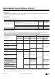
Revision Record The table below summarizes the changes to this manual since last printing of FC9Y-B812-0A in June, 2006. Revision Description of Change Page Analog I/O Modules (Ladder Refresh Type) Four analog input and output modules are added. 2-43, 6-5, 24-1 AS-Interface Master Module Compatibility AS-Interface master module is added.
PREFACE-4 « FC4A MICROSMART USER’S MANUAL »
TABLE OF CONTENTS CHAPTER 1: GENERAL INFORMATION About the MicroSmart . . . . . . . . . . . . . . . . . . . . . . . . . . . . . . . . . . . . . . . . . . . . . Features . . . . . . . . . . . . . . . . . . . . . . . . . . . . . . . . . . . . . . . . . . . . . . . . . . . . . . . Special Functions . . . . . . . . . . . . . . . . . . . . . . . . . . . . . . . . . . . . . . . . . . . . . . . . System Setup . . . . . . . . . . . . . . . . . . . . . . . . . . . . . . . . . . . . . . . . . . . . . . . . . . .
TABLE OF CONTENTS CHAPTER 5: SPECIAL FUNCTIONS Function Area Settings . . . . . . . . . . . . . . . . . . . . . . . . . . . . . . . . . . . . . . . . . . . . . 5-1 Stop Input and Reset Input . . . . . . . . . . . . . . . . . . . . . . . . . . . . . . . . . . . . . . . . . . 5-2 Run/Stop Selection at Memory Backup Error . . . . . . . . . . . . . . . . . . . . . . . . . . . . . 5-3 Keep Designation for Internal Relays, Shift Registers, Counters, and Data Registers 5-4 High-speed Counter . . . . . . . . .
TABLE OF CONTENTS CHAPTER 8: ADVANCED INSTRUCTIONS Advanced Instruction List . . . . . . . . . . . . . . . . . . . . . . . . . . . . . . . . . . . . . . . . . . . Advanced Instruction Applicable CPU Modules . . . . . . . . . . . . . . . . . . . . . . . . . . . . Structure of an Advanced Instruction . . . . . . . . . . . . . . . . . . . . . . . . . . . . . . . . . . . Input Condition for Advanced Instructions . . . . . . . . . . . . . . . . . . . . . . . . . . . . . . . Source and Destination Operands .
TABLE OF CONTENTS CHAPTER 14: DATA CONVERSION INSTRUCTIONS HTOB (Hex to BCD) . . . . . . . . . . . . . . . . . . . . . . . . . . . . . . . . . . . . . . . . . . . . . . 14-1 BTOH (BCD to Hex) . . . . . . . . . . . . . . . . . . . . . . . . . . . . . . . . . . . . . . . . . . . . . . 14-2 HTOA (Hex to ASCII) . . . . . . . . . . . . . . . . . . . . . . . . . . . . . . . . . . . . . . . . . . . . . . 14-3 ATOH (ASCII to Hex) . . . . . . . . . . . . . . . . . . . . . . . . . . . . . . . . . . . . . . . . .
TABLE OF CONTENTS CHAPTER 19: COORDINATE CONVERSION INSTRUCTIONS XYFS (XY Format Set) . . . . . . . . . . . . . . . . . . . . . . . . . . . . . . . . . . . . . . . . . . . . . 19-1 CVXTY (Convert X to Y) . . . . . . . . . . . . . . . . . . . . . . . . . . . . . . . . . . . . . . . . . . . . 19-2 CVYTX (Convert Y to X) . . . . . . . . . . . . . . . . . . . . . . . . . . . . . . . . . . . . . . . . . . . . 19-3 CHAPTER 20: PULSE INSTRUCTIONS PULS1 (Pulse Output 1) . . . . . . . . . . . . . . . . . . . .
TABLE OF CONTENTS CHAPTER 26: COMPUTER LINK COMMUNICATION Computer Link System Setup (1:N Computer Link System) . . . . . . . . . . . . . . . . . . Programming WindLDR . . . . . . . . . . . . . . . . . . . . . . . . . . . . . . . . . . . . . . . . . . . . Monitoring PLC Status . . . . . . . . . . . . . . . . . . . . . . . . . . . . . . . . . . . . . . . . . . . . RS232C/RS485 Converter FC2A-MD1 . . . . . . . . . . . . . . . . . . . . . . . . . . . . . . . . . CHAPTER 27: MODEM MODE System Setup . . .
1: GENERAL INFORMATION Introduction This chapter describes general information for understanding the MicroSmart’s powerful capabilities and system setups to use the MicroSmart in various ways of communication. About the MicroSmart IDEC’s MicroSmart is a new family of micro programmable logic controllers available in two styles of CPU modules; allin-one and slim types.
1: GENERAL INFORMATION HMI Module (all CPU modules) An optional HMI module can be installed on any all-in-one type CPU module, and also on the HMI base module mounted next to any slim type CPU module. The HMI module makes it possible to manipulate the RAM data in the CPU module without using the Online menu options in WindLDR.
1: GENERAL INFORMATION Catch Input Four inputs can be used as catch inputs. The catch input makes sure to receive short input pulses (rising pulse of 40 µs or falling pulse of 150 µs minimum) from sensors without regard to the scan time. Interrupt Input Four inputs can be used as interrupt inputs. When a quick response to an external input is required, such as positioning control, the interrupt input can call a subroutine to execute an interrupt program.
1: GENERAL INFORMATION System Setup This section illustrates system setup configurations for using powerful communication functions of the MicroSmart. User Communication and Modem Communication System The all-in-one 16- and 24-I/O type MicroSmart CPU modules have port 1 for RS232C communication and port 2 connector. An optional RS232C or RS485 communication adapter can be installed on the port 2 connector.
1: GENERAL INFORMATION Computer Link System When the MicroSmart is connected to a computer, operating status and I/O status can be monitored on the computer, data in the CPU module can be monitored or updated, and user programs can be downloaded and uploaded.
1: GENERAL INFORMATION Data Link System With an optional RS485 communication adapter installed on the port 2 connector, one 16- or 24-I/O type CPU module at the master station can communicate with 31 slave stations through the RS485 line to exchange data and perform distributed control effectively. The RS485 terminals are connected with each other using a 2-core twisted pair cable. The same data link system can also be set up using any slim type CPU modules mounted with RS485 communication modules.
1: GENERAL INFORMATION Operator Interface Communication System The MicroSmart can communicate with IDEC’s HG series operator interfaces through RS232C port 1 and port 2. Optional cables are available for connection between the MicroSmart and HG series operator interfaces. When installing an optional RS232C communication adapter on the all-in-one type CPU module or an optional RS232C communication module on the slim type CPU module, two operator interfaces can be connected to one MicroSmart CPU module.
1: GENERAL INFORMATION AS-Interface Network Actuator-Sensor-Interface, abbreviated AS-Interface The MicroSmart can be connected to the AS-Interface network using the AS-Interface master module (FC4A-AS62M). AS-Interface is a type of field bus that is primarily intended to be used to control sensors and actuators. AS-Interface is a network system that is compatible with the IEC62026 standard and is not proprietary to any one manufacturer.
2: MODULE SPECIFICATIONS Introduction This chapter describes MicroSmart modules, parts names, and specifications of each module. Available modules include all-in-one type and slim type CPU modules, digital input modules, digital output modules, mixed I/O modules, analog I/O modules, HMI module, HMI base module, communication adapters, communication modules, memory cartridge, and clock cartridge. CPU Modules (All-in-One Type) All-in-one type CPU modules are available in 10-, 16-, and 24-I/O types.
2: MODULE SPECIFICATIONS (1) Power Supply Terminals Connect power supply to these terminals. Power voltage 100-240V AC or 24V DC. See page 3-16. (2) Sensor Power Terminals (AC power type only) For supplying power to sensors (24V DC, 250mA). These terminals can be used for supplying power to input circuits. Use the sensor power supply only for supplying power to input devices connected to the MicroSmart.
2: MODULE SPECIFICATIONS General Specifications (All-in-One Type CPU Module) Normal Operating Conditions CPU Module AC Power Type FC4A-C10R2 FC4A-C16R2 FC4A-C24R2 DC Power Type FC4A-C10R2C FC4A-C16R2C FC4A-C24R2C Operating Temperature 0 to 55°C (operating ambient temperature) Storage Temperature –25 to +70°C Relative Humidity 10 to 95% (non-condensing) Pollution Degree 2 (IEC 60664-1) Degree of Protection IP20 (IEC 60529) Corrosion Immunity Atmosphere free from corrosive gases Altitude
2: MODULE SPECIFICATIONS Function Specifications (All-in-One Type CPU Module) CPU Module Specifications FC4A-C10R2 FC4A-C10R2C CPU Module FC4A-C16R2 FC4A-C16R2C FC4A-C24R2 FC4A-C24R2C Program Capacity 4,800 bytes (800 steps) 15,000 bytes (2,500 steps) 27,000 bytes (4,500 steps) Expandable I/O Modules — — 4 modules Input 6 9 14 Output 4 7 10 I/O Points User Program Storage RAM Backup EEPROM Backup Duration Approx.
2: MODULE SPECIFICATIONS Communication Function Communication Port Port 2 (RS232C) Communication Adapter Port 1 (RS232C) Port 2 (RS485) Communication Adapter Standards EIA RS232C EIA RS232C EIA RS485 Maximum Baud Rate 19,200 bps 19,200 bps Computer link: 19,200 bps Data link: 38,400 bps Maintenance Communication (Computer Link) Possible Possible Possible User Communication Possible Possible Not possible Modem Communication Not possible Possible Not possible Data Link Communication N
2: MODULE SPECIFICATIONS DC Input Specifications (All-in-One Type CPU Module) FC4A-C10R2 FC4A-C10R2C FC4A-C16R2 FC4A-C16R2C 9 points in 1 common line Input Points and Common Line 6 points in 1 common line Terminal Arrangement See CPU Module Terminal Arrangement on pages 2-8 and 2-9. Rated Input Voltage 24V DC sink/source input signal Input Voltage Range 20.4 to 28.
2: MODULE SPECIFICATIONS Relay Output Specifications (All-in-One Type CPU Module) FC4A-C10R2 FC4A-C10R2C CPU Module No. of Outputs Output Points per Common Line FC4A-C16R2 FC4A-C16R2C FC4A-C24R2 FC4A-C24R2C 4 points 7 points 10 points COM0 3 NO contacts 4 NO contacts 4 NO contacts COM1 1 NO contact 2 NO contacts 4 NO contacts COM2 — 1 NO contact 1 NO contact COM3 — — 1 NO contact Terminal Arrangement See CPU Module Terminal Arrangement on pages 2-8 and 2-9.
2: MODULE SPECIFICATIONS CPU Module Terminal Arrangement (All-in-One Type) The input and output terminal arrangements of the all-in-one type CPU modules are shown below. AC Power Type CPU Module FC4A-C10R2 Sensor Power Terminals Input Terminals AC Power Terminals Output Terminals +24V 0V DC OUT DC IN COM 100-240VAC L N 0 1 2 Ry.OUT COM0 0 3 1 4 5 Ry.
2: MODULE SPECIFICATIONS DC Power Type CPU Module FC4A-C10R2C Input Terminals DC IN COM DC Power Terminals Output Terminals 24VDC + 0 1 2 Ry.OUT COM0 0 – 3 1 4 5 Ry.OUT COM1 3 2 FC4A-C16R2C Input Terminals DC IN COM 24VDC DC Power Terminals Output Terminals + 0 1 2 Ry.OUT COM0 0 – 3 1 4 2 5 3 6 10 7 Ry.OUT COM1 4 5 Ry.OUT COM2 6 FC4A-C24R2C Input Terminals DC IN COM 24VDC DC Power Terminals Output Terminals + – 0 1 Ry.OUT COM0 0 2 3 1 4 2 5 3 6 Ry.
2: MODULE SPECIFICATIONS I/O Wiring Diagrams (All-in-One Type CPU Module) The input and output wiring examples of the CPU modules are shown below. For wiring precautions, see pages 3-13 through 3-16.
2: MODULE SPECIFICATIONS CPU Modules (Slim Type) Slim type CPU modules are available in 20- and 40-I/O types. The 20-I/O type has 12 input and 8 output terminals, and the 40-I/O type has 24 input and 16 output terminals. The FC4A-D20RK1 and FC4A-D20RS1 have 2 transistor outputs used for high-speed outputs and pulse outputs in addition to 10 relay outputs.
2: MODULE SPECIFICATIONS (1) Power Supply Terminals Connect power supply to these terminals. Power voltage 24V DC. See page 3-17. (2) I/O Terminals For connecting input and output signals. The input terminals accept both sink and source 24V DC input signals. Transistor and relay output types are available. Transistor output type has MIL connectors and relay output type has removable screw connectors. (3) Expansion Connector For connecting digital and analog I/O modules.
2: MODULE SPECIFICATIONS General Specifications (Slim Type CPU Module) Normal Operating Conditions FC4A-D20K3 FC4A-D20S3 CPU Module FC4A-D20RK1 FC4A-D20RS1 FC4A-D40K3 FC4A-D40S3 Operating Temperature 0 to 55°C (operating ambient temperature) Storage Temperature –25 to +70°C Relative Humidity 10 to 95% (non-condensing) Pollution Degree 2 (IEC 60664-1) Degree of Protection IP20 (IEC 60529) Corrosion Immunity Atmosphere free from corrosive gases Altitude Operation: 0 to 2,000m (0 to 6,565 feet
2: MODULE SPECIFICATIONS Function Specifications (Slim Type CPU Module) CPU Module Specifications FC4A-D20K3 FC4A-D20S3 CPU Module 27,000 bytes (4,500 steps) Program Capacity Expandable I/O Modules I/O Points 31,200 bytes (5,200 steps) 64,500 bytes (10,750 steps) (Note 1, Note 2) 12 Output 8 Expansion: 128 12 Expansion: 224 8 24 Expansion: 224 16 EEPROM Backup Duration Approx.
2: MODULE SPECIFICATIONS Communication Function Communication Port Standards Port 2 (RS232C) Communication Module Communication Adapter Port 1 (RS232C) EIA RS232C Port 2 (RS485) Communication Module Communication Adapter EIA RS232C EIA RS485 Maximum Baud Rate 19,200 bps 19,200 bps Computer link: 19,200 bps User comm.
2: MODULE SPECIFICATIONS DC Input Specifications (Slim Type CPU Module) FC4A-D20K3 FC4A-D20S3 FC4A-D20RK1 FC4A-D20RS1 12 points in 1 common line FC4A-D40K3 FC4A-D40S3 Input Points and Common Lines 12 points in 1 common line Terminal Arrangement See CPU Module Terminal Arrangement on pages 2-19 through 2-22. Rated Input Voltage 24V DC sink/source input signal Input Voltage Range 20.4 to 26.
2: MODULE SPECIFICATIONS Transistor Sink and Source Output Specifications (Slim Type CPU Module) FC4A-D20K3 FC4A-D20RK1 FC4A-D40K3 CPU Module FC4A-D20S3 FC4A-D20RS1 FC4A-D40S3 Output Type Sink output Source output Output Points and Common Lines FC4A-D20K3/S3: FC4A-D20RK1/RS1: FC4A-D40K3/S3: Terminal Arrangement See CPU Module Terminal Arrangement on pages 2-19 through 2-22. Rated Load Voltage 24V DC Operating Load Voltage Range 20.4 to 28.8V DC Rated Load Current 0.
2: MODULE SPECIFICATIONS Relay Output Specifications (Slim Type CPU Module) CPU Module FC4A-D20RK1 No. of Outputs FC4A-D20RS1 8 points including 2 transistor output points Output Points per Common Line COM0 (2 points transistor sink output) COM1 3 NO contacts COM2 2 NO contacts COM3 1 NO contact (2 points transistor source output) Terminal Arrangement See CPU Module Terminal Arrangement on page 2-20. Maximum Load Current 2A per point 8A per common line Minimum Switching Load 0.1 mA/0.
2: MODULE SPECIFICATIONS CPU Module Terminal Arrangement and I/O Wiring Diagrams (Slim Type) FC4A-D20K3 (20-I/O Transistor Sink Output Type CPU Module) Applicable Connector: FC4A-PMC26P (not supplied with the CPU module) Source Input Wiring 2-wire Sensor – + NPN – 24V DC + Terminal No. 26 24 22 20 18 16 14 12 10 8 6 4 2 Sink Output Wiring Input I0 I1 I2 I3 I4 I5 I6 I7 I10 I11 I12 I13 COM Terminal No.
2: MODULE SPECIFICATIONS FC4A-D20RK1 (20-I/O Relay and Transistor Sink High-speed Output Type CPU Module) Applicable Terminal Blocks: TB1 (Left Side) FC4A-PMT13P (supplied with the CPU module) TB2 (Right Side) FC4A-PMTK16P (supplied with the CPU module) Source Input Wiring TB1 2-wire Sensor Terminal No. – + 1 2 3 4 5 6 NPN 7 8 9 – 24V DC + 10 11 12 13 Sink Output Wiring Input I0 I1 I2 I3 I4 I5 I6 I7 I10 I11 I12 I13 COM TB2 Terminal No.
2: MODULE SPECIFICATIONS FC4A-D40K3 (40-I/O Transistor Sink Output Type CPU Module) Applicable Connector: FC4A-PMC26P (not supplied with the CPU module) Source Input Wiring Sink Output Wiring CN1 2-wire Sensor Terminal No. – + 26 24 22 20 18 16 NPN 14 12 10 – 24V DC + 8 6 4 2 Input I0 I1 I2 I3 I4 I5 I6 I7 I10 I11 I12 I13 COM Terminal No. 25 23 21 19 17 15 13 11 9 7 5 3 1 Output Q0 Q1 Q2 Q3 Q4 Q5 Q6 Q7 COM(–) COM(–) COM(–) +V +V Load L L L L L L L L CN2 Terminal No.
2: MODULE SPECIFICATIONS FC4A-D40S3 (40-I/O Transistor Source Output Type CPU Module) Applicable Connector: FC4A-PMC26P (not supplied with the CPU module) Sink Input Wiring Source Output Wiring CN1 2-wire Sensor Terminal No. + – 26 24 22 20 18 16 PNP 14 12 10 + 24V DC – 8 6 4 2 Input I0 I1 I2 I3 I4 I5 I6 I7 I10 I11 I12 I13 COM Terminal No. 25 23 21 19 17 15 13 11 9 7 5 3 1 Output Q0 Q1 Q2 Q3 Q4 Q5 Q6 Q7 COM(+) COM(+) COM(+) –V –V Load L L L L L L L L CN2 Terminal No.
2: MODULE SPECIFICATIONS Input Modules Digital input modules are available in 8-, 16-, and 32-point DC input modules and an 8-point AC input module with a screw terminal block or plug-in connector for input wiring. All DC input modules accept both sink and source DC input signals. The input modules can be connected to the all-in-one 24-I/O type CPU module and all slim type CPU modules to expand input terminals. The all-in-one 10- and 16-I/O type CPU modules cannot connect input modules.
2: MODULE SPECIFICATIONS DC Input Module Specifications Type No. FC4A-N08B1 FC4A-N16B1 16 points in 1 common line FC4A-N16B3 FC4A-N32B3 16 points in 1 common line 32 points in 2 common lines Input Points and Common Lines 8 points in 1 common line Terminal Arrangement See Input Module Terminal Arrangement on pages 2-26 through 2-28. Rated Input Voltage 24V DC sink/source input signal Input Voltage Range 20.4 to 28.8V DC Rated Input Current 7 mA/point (24V DC) 5 mA/point (24V DC) 4.
2: MODULE SPECIFICATIONS AC Input Module Specifications Type No. FC4A-N08A11 Input Points and Common Lines 8 points in 2 common lines Terminal Arrangement See Input Module Terminal Arrangement on page 2-29. Rated Input Voltage 100 to 120V AC (50/60 Hz) Input Voltage Range 85 to 132V AC Rated Input Current 17 mA/point (120V AC, 60 Hz) Input Type AC input, Type 2 (IEC 61131-2) Input Impedance 0.
2: MODULE SPECIFICATIONS DC Input Module Terminal Arrangement and Wiring Diagrams FC4A-N08B1 (8-point DC Input Module) — Screw Terminal Type Applicable Terminal Block: FC4A-PMT10P (supplied with the input module) DC.IN Source Input Wiring 0 1 2 3 4 5 6 7 2-wire Sensor – + NPN – 24V DC + Sink Input Wiring 0 1 Terminal No. 0 1 2 3 4 5 6 7 COM COM Input I0 I1 I2 I3 I4 I5 I6 I7 COM COM 2-wire Sensor + – PNP + 24V DC – Input I0 I1 I2 I3 I4 I5 I6 I7 COM COM Terminal No.
2: MODULE SPECIFICATIONS FC4A-N16B3 (16-point DC Input Module) — Connector Type Applicable Connector: FC4A-PMC20P (not supplied with the input module) Source Input Wiring 2-wire Sensor – + NPN – 24V DC + Terminal No. 20 18 16 14 12 10 8 6 4 2 Input I0 I1 I2 I3 I4 I5 I6 I7 COM NC Terminal No. 19 17 15 13 11 9 7 5 3 1 Input I10 I11 I12 I13 I14 I15 I16 I17 COM NC 2-wire Sensor Terminal No. 20 18 16 14 12 10 8 6 4 2 Input I0 I1 I2 I3 I4 I5 I6 I7 COM NC Terminal No.
2: MODULE SPECIFICATIONS FC4A-N32B3 (32-point DC Input Module) — Connector Type Applicable Connector: FC4A-PMC20P (not supplied with the input module) • COM0 terminals are connected together internally. • COM1 terminals are connected together internally. • COM0 and COM1 terminals are not connected together internally. • For input wiring precautions, see page 3-13. Source Input Wiring CN1 No. 2-wire Sensor – + 20 18 16 14 12 NPN 10 – 24V DC 8 + 6 4 2 Input I0 I1 I2 I3 I4 I5 I6 I7 COM0 NC No.
2: MODULE SPECIFICATIONS AC Input Module Terminal Arrangement and Wiring Diagrams FC4A-N08A11 (8-point AC Input Module) — Screw Terminal Type Applicable Terminal Block: FC4A-PMT11P (supplied with the input module) AC.IN 0 1 2 3 4 5 6 7 AC 0 1 2 Terminal No. 0 1 2 3 COM0 NC 4 5 6 7 COM1 Output I0 I1 I2 I3 COM0 NC I4 I5 I6 I7 COM1 3 COM0 NC AC 4 5 • Two COM terminals are not connected together internally. • For input wiring precautions, see page 3-13.
2: MODULE SPECIFICATIONS Output Modules Digital output modules are available in 8- and 16-point relay output modules, 8-, 16- and 32-point transistor sink output modules, and 8-, 16- and 32-point transistor source output modules with a screw terminal block or plug-in connector for output wiring. The output modules can be connected to the all-in-one 24-I/O type CPU module and all slim type CPU modules to expand output terminals. The all-in-one 10- and 16-I/O type CPU modules cannot connect output modules.
2: MODULE SPECIFICATIONS Relay Output Module Specifications Type No. FC4A-R081 FC4A-R161 Output Points and Common Lines 8 NO contacts in 2 common lines 16 NO contacts in 2 common lines Terminal Arrangement See Relay Output Module Terminal Arrangement on page 2-32. 2A per point Maximum Load Current 7A per common line 8A per common line Minimum Switching Load 0.1 mA/0.
2: MODULE SPECIFICATIONS Relay Output Module Terminal Arrangement and Wiring Diagrams FC4A-R081 (8-point Relay Output Module) — Screw Terminal Type Applicable Terminal Block: FC4A-PMT11P (supplied with the output module) Ry.OUT 0 1 2 3 4 5 6 7 Fuse 0 1 Fuse – DC + Fuse + – DC Fuse AC Fuse – DC + Fuse + – DC Fuse AC Load L L L L L L L L 2 Terminal No.
2: MODULE SPECIFICATIONS Transistor Sink Output Module Specifications Type No. FC4A-T08K1 FC4A-T16K3 FC4A-T32K3 Output Type Transistor sink output Output Points and Common Lines 8 points in 1 common line Terminal Arrangement See Transistor Sink Output Module Terminal Arrangement on pages 2-34 and 2-35. Rated Load Voltage 24V DC Operating Load Voltage Range 20.4 to 28.8V DC Rated Load Current 0.3A per output point 0.1A per output point Maximum Load Current (at 28.8V DC) 0.
2: MODULE SPECIFICATIONS Transistor Sink Output Module Terminal Arrangement and Wiring Diagrams FC4A-T08K1 (8-point Transistor Sink Output Module) — Screw Terminal Type Applicable Terminal Block: FC4A-PMT10P (supplied with the output module) Tr.OUT 0 1 2 3 4 5 6 7 Fuse Fuse + – Load L L L L L L L L 0 1 Terminal No. 0 1 2 3 4 5 6 7 COM(–) +V Output Q0 Q1 Q2 Q3 Q4 Q5 Q6 Q7 COM(–) +V 2 3 • Connect a fuse appropriate for the load. • For output wiring precautions, see page 3-14.
2: MODULE SPECIFICATIONS FC4A-T32K3 (32-point Transistor Sink Output Module) — Connector Type Applicable Connector: FC4A-PMC20P (not supplied with the output module) Fuse Load L L L L L L L L + – Fuse Load L L L L L L L L + – CN1 Terminal No. 20 18 16 14 12 10 8 6 4 2 Output Q0 Q1 Q2 Q3 Q4 Q5 Q6 Q7 COM0(–) +V0 Terminal No. 19 17 15 13 11 9 7 5 3 1 Output Q10 Q11 Q12 Q13 Q14 Q15 Q16 Q17 COM0(–) +V0 Load L L L L L L L L CN2 Terminal No.
2: MODULE SPECIFICATIONS Transistor Source Output Module Specifications Type No. FC4A-T08S1 FC4A-T16S3 FC4A-T32S3 Output Type Transistor source output Output Points and Common Lines 8 points in 1 common line Terminal Arrangement See Transistor Source Output Module Terminal Arrangement on pages 2-37 and 2-38. Rated Load Voltage 24V DC Operating Load Voltage Range 20.4 to 28.8V DC Rated Load Current 0.3A per output point 0.1A per output point Maximum Load Current (at 28.8V DC) 0.
2: MODULE SPECIFICATIONS Transistor Source Output Module Terminal Arrangement and Wiring Diagrams FC4A-T08S1 (8-point Transistor Source Output Module) — Screw Terminal Type Applicable Terminal Block: FC4A-PMT10P (supplied with the output module) Tr.OUT 0 1 2 3 4 5 6 7 – + Fuse Load L L L L L L L L 0 1 Terminal No. 0 1 2 3 4 5 6 7 COM(+) –V Output Q0 Q1 Q2 Q3 Q4 Q5 Q6 Q7 COM(+) –V 2 3 4 • Connect a fuse appropriate for the load. • For output wiring precautions, see page 3-14.
2: MODULE SPECIFICATIONS FC4A-T32S3 (32-point Transistor Source Output Module) — Connector Type Applicable Connector: FC4A-PMC20P (not supplied with the output module) Fuse Load L L L L L L L L – + Fuse – + Load L L L L L L L L CN1 Terminal No. 20 18 16 14 12 10 8 6 4 2 Output Q0 Q1 Q2 Q3 Q4 Q5 Q6 Q7 COM0(+) –V0 Terminal No. 19 17 15 13 11 9 7 5 3 1 Output Q10 Q11 Q12 Q13 Q14 Q15 Q16 Q17 COM0(+) –V0 Load L L L L L L L L CN2 Terminal No.
2: MODULE SPECIFICATIONS Mixed I/O Modules The 4-in/4-out mixed I/O module has 4-point DC sink/source inputs and 4-point relay outputs, with a screw terminal block for I/O wiring. The 16-in/8-out mixed I/O module has 16-point DC sink/source inputs and 8-point relay outputs, with a wire-clamp terminal block for I/O wiring. The mixed I/O modules can be connected to the all-in-one 24-I/O type CPU module and all slim type CPU modules to expand input and output terminals.
2: MODULE SPECIFICATIONS Mixed I/O Module Specifications Type No. FC4A-M08BR1 FC4A-M24BR2 I/O Points 4 inputs in 1 common line 4 outputs in 1 common line Terminal Arrangement See Mixed I/O Module Terminal Arrangement on pages 2-41 and 2-42. Connector on Mother Board MC1.5/11-G-3.
2: MODULE SPECIFICATIONS Relay Output Specifications (Mixed I/O Module) Type No. FC4A-M08BR1 FC4A-M24BR2 Output Points and Common Lines 4 NO contacts in 1 common line 8 NO contacts in 2 common lines Maximum Load Current 2A per point 7A per common line Minimum Switching Load 0.1 mA/0.
2: MODULE SPECIFICATIONS FC4A-M24BR2 (Mixed I/O Module) — Wire-clamp Terminal Type Source Input Wiring 2-wire Sensor – + NPN – 24V DC + Terminal No. 1 2 3 4 5 6 7 8 9 10 11 12 13 14 15 16 17 Sink Input Wiring Input I0 I1 I2 I3 I4 I5 I6 I7 I10 I11 I12 I13 I14 I15 I16 I17 COM0 2-wire Sensor + – PNP + 24V DC – Terminal No.
2: MODULE SPECIFICATIONS Analog I/O Modules Analog I/O modules are available in 3-I/O types, 2-, 4-, and 8-input types, and 1- and 2-output types. The input channel can accept voltage and current signals, thermocouple and resistance thermometer signals, or thermistor signals. The output channel generates voltage and current signals. Analog I/O Module Type Numbers Name Analog I/O Module Analog Input Module Analog Output Module I/O Signal I/O Points Category Type No.
2: MODULE SPECIFICATIONS Parts Description (1) Expansion Connector (2) Module Label (3) Power LED (PWR) (3) Status LED (STAT) (4) Terminal No. (5) Cable Terminal The terminal style depends on the model of analog I/O modules. (1) Expansion Connector Connects to the CPU and other I/O modules. (The all-in-one 10- and 16-I/O type CPU modules cannot be connected.) (2) Module Label Indicates the analog I/O module Type No. and specifications.
2: MODULE SPECIFICATIONS Analog I/O Module Specifications General Specifications (END Refresh Type) Type No. FC4A-L03A1 FC4A-L03AP1 FC4A-J2A1 FC4A-K1A1 Rated Power Voltage 24V DC Allowable Voltage Range 20.4 to 28.8V DC Terminal Arrangement See Analog I/O Module Terminal Arrangement on pages 2-52 to 2-55. Connector on Mother Board MC1.5/11-G-3.
2: MODULE SPECIFICATIONS Analog Input Specifications (END Refresh Type) Type No.
2: MODULE SPECIFICATIONS Type No.
2: MODULE SPECIFICATIONS Analog Input Specifications (Ladder Refresh Type) Type No.
2: MODULE SPECIFICATIONS Type No. FC4A-J4CN1 / FC4A-J8C1 Analog Input Signal Type Voltage Input Current Input FC4A-J4CN1 Resistance Thermometer Thermocouple Pt100: Approx. K: Approx. 24000 increments (15 bits) Digital Resolution 50000 increments (16 bits) J: Approx. 33000 increments (15 bits) T: Approx. 10000 increments (14 bits) Data Input Value of LSB 0.2 mV 0.32 µA Default: 0 to 50000 Data Type in Application Program 6400 increments (13 bits) Pt1000: Approx.
2: MODULE SPECIFICATIONS Analog Input Specifications (Ladder Refresh Type) Type No. FC4A-J8AT1 Analog Input Signal Type NTC Thermistor Input Range –50 to 150°C Applicable Thermistor 100 kΩ maximum Input Detection Current 0.
2: MODULE SPECIFICATIONS Analog Output Specifications Category END Refresh Type Type No. FC4A-L03A1 Output Range Load DA Conversion Output Error 0 to 10V DC Current 4 to 20 mA DC Ladder Refresh FC4A-K1A1 FC4A-K2C1 –10 to +10V DC Load Impedance 1 (2) kΩ minimum (voltage), 300Ω maximum (current) (Note 1) Applicable Load Type Resistive load Settling Time 10 (50) ms (Note 1) Total Output System Transfer Time Settling time + 1 scan time Maximum Error at 25°C ±0.
2: MODULE SPECIFICATIONS Analog I/O Module Terminal Arrangement and Wiring Diagrams FC4A-L03A1 (Analog I/O Module) — Screw Terminal Type Applicable Terminal Block: FC4A-PMT11P (supplied with the analog I/O module) Fuse 24V DC – + Analog voltage/current input device Analog voltage/current output device Analog voltage/current output device Terminal No.
2: MODULE SPECIFICATIONS FC4A-J2A1 (Analog Input Module) — Screw Terminal Type Applicable Terminal Block: FC4A-PMT11P (supplied with the analog input module) Fuse 24V DC – + Analog voltage/current output device Analog voltage/current output device Terminal No. + Channel – 24V DC NC NC NC + – NC + – + – + – — IN0 IN1 • Connect a fuse appropriate for the applied voltage and current draw, at the position shown in the diagram.
2: MODULE SPECIFICATIONS FC4A-J8C1 (Analog Input Module) — Screw Terminal Type Applicable Terminal Block: FC4A-PMT10P (supplied with the analog input module) Fuse 24V DC – + Analog voltage output device Analog current output device + – + – • Connect a fuse appropriate for the applied voltage and current draw, at the position shown in the diagram. This is required when equipment containing the MicroSmart is destined for Europe. • Do not connect any wiring to unused terminals.
2: MODULE SPECIFICATIONS FC4A-K1A1 (Analog Output Module) — Screw Terminal Type Applicable Terminal Block: FC4A-PMT11P (supplied with the analog output module) Fuse 24V DC – + Analog voltage/current input device Terminal No. + Channel – 24V DC + + – – NC NC NC NC NC NC OUT — — • Connect a fuse appropriate for the applied voltage and current draw, at the position shown in the diagram. This is required when equipment containing the MicroSmart is destined for Europe.
2: MODULE SPECIFICATIONS Type of Protection Input Circuits FC4A-L03A1, FC4A-J2A1 (Ver. 200 or higher) FC4A-L03AP1 (Ver.
2: MODULE SPECIFICATIONS Power Supply for Analog I/O Modules When supplying power to the analog I/O modules, take the following considerations. • Power Supply for FC4A-L03A1, FC4A-L03AP1, FC4A-J2A1, and FC4A-K1A1 Use separate power supplies for the MicroSmart CPU module and FC4A-L03A1, FC4A-L03AP1, FC4A-J2A1, and FC4AK1A1. Power up the analog I/O modules at least 1 second earlier than the CPU module. This is recommended to ensure correct operation of the analog I/O control.
2: MODULE SPECIFICATIONS AS-Interface Master Module The AS-Interface master module can be used with FC4A-D20RK1, FC4A-D20RS1, FC4A-D40K3, and FC4A-D40S3 CPU modules to communicate digital data with slaves, such as sensor, actuator, and remote I/O data. One AS-Interface master module can be used with one CPU module. The AS-Interface master module can connect a maximum of 62 digital I/O slaves.
2: MODULE SPECIFICATIONS General Specifications (AS-Interface Module) Operating Temperature 0 to 55°C (operating ambient temperature, no freezing) Storage Temperature –25 to +70°C (no freezing) Relative Humidity Level RH1, 30 to 95% (non-condensing) Pollution Degree 2 (IEC 60664) Degree of Protection IP20 Corrosion Immunity Free from corrosive gases Altitude Operation: 0 to 2,000m (0 to 6,565 feet) Transport: 0 to 3,000m (0 to 9,840 feet) When mounted on a DIN rail: 10 to 57 Hz amplitude 0.
2: MODULE SPECIFICATIONS HMI Module The optional HMI module can mount on any all-in-one type CPU module, and also on the HMI base module mounted next to any slim type CPU module. The HMI module makes it possible to manipulate the RAM data in the CPU module without using the Online menu options in WindLDR. For details about operating the HMI module, see page 5-32. For installing and removing the HMI module, see pages 3-3 and 3-4. HMI Module Type Number Module Name Type No.
2: MODULE SPECIFICATIONS HMI Base Module The HMI base module is used to install the HMI module when using the slim type CPU module. The HMI base module also has a port 2 connector to attach an optional RS232C or RS485 communication adapter. When using the all-in-one type CPU module, the HMI base module is not needed to install the HMI module. HMI Base Module Type Number Module Name Type No.
2: MODULE SPECIFICATIONS Communication Adapters and Communication Modules All MicroSmart CPU modules have communication port 1 for RS232C communication. In addition, all-in-one 16- and 24I/O type CPU modules have a port 2 connector. An optional communication adapter can be installed on the port 2 connector for RS232C or RS485 communication. The 10-I/O type CPU module does not have a port 2 connector.
2: MODULE SPECIFICATIONS Communication Adapter and Communication Module Specifications FC4A-PC1 FC4A-HPC1 Type No. Standards EIA RS232C FC4A-PC2 FC4A-HPC2 FC4A-PC3 FC4A-HPC3 EIA RS485 EIA RS485 Maximum Baud Rate 19,200 bps 19,200 bps Computer link: 19,200 bps User com.
2: MODULE SPECIFICATIONS After installing the communication adapter on an all-in-one type CPU module, view the communication adapter through the dummy cartridge opening, and check to see that the PC board of the communication adapter is in a lower level than the top of the terminal block. Communication Adapter PC Board Communication Module When installing a communication module on the slim type CPU module, remove the communication connector cover from the slim type CPU module. See page 3-6.
2: MODULE SPECIFICATIONS Memory Cartridge A user program can be stored on an optional memory cartridge installed on a MicroSmart CPU module from a computer running WindLDR, and the memory cartridge can be installed on another MicroSmart CPU module of the same type. Using a memory cartridge, the CPU module can exchange user programs without using a computer. This feature is available on all models of CPU modules. Memory Cartridge Type Number Module Name 32KB Memory Cartridge 64KB Memory Cartridge Type No.
2: MODULE SPECIFICATIONS Downloading and Uploading User Program to and from Memory Cartridge When a memory cartridge is installed on the CPU module, a user program is downloaded to and uploaded from the memory cartridge using WindLDR on a computer. When a memory cartridge is not installed on the CPU module, a user program is downloaded to and uploaded from the CPU module. For the procedures to download a user program from WindLDR on a computer, see page 4-8.
2: MODULE SPECIFICATIONS Installing and Removing the Memory Cartridge Caution • Before installing or removing the memory cartridge, turn off the power to the MicroSmart CPU module. Otherwise, the memory cartridge or CPU module may be damaged, or the MicroSmart may not operate correctly. • Do not touch the connector pins with hand, otherwise electrostatic discharge may damage the internal elements. All-in-One Type CPU Module The cartridge connector is normally closed with a dummy cartridge.
2: MODULE SPECIFICATIONS Clock Cartridge With the optional clock cartridge installed on any type of MicroSmart CPU modules, the MicroSmart can be used for time-scheduled control such as illumination and air conditioners. For setting the calendar/clock, see page 15-5. Clock Cartridge Type Number Module Name Clock Cartridge Type No. FC4A-PT1 Clock Cartridge Specifications Accuracy ±30 sec/month (typical) at 25°C Backup Duration Approx.
2: MODULE SPECIFICATIONS Dimensions All MicroSmart modules have the same profile for consistent mounting on a DIN rail. CPU Modules FC4A-C10R2, FC4A-C10R2C, FC4A-C16R2, FC4A-C16R2C 70.0 4.5* 90.0 80.0 *8.5 mm when the clamp is pulled out. FC4A-C24R2, FC4A-C24R2C 70.0 4.5* 90.0 95.0 *8.5 mm when the clamp is pulled out. All dimensions in mm.
2: MODULE SPECIFICATIONS FC4A-D20K3, FC4A-D20S3 11.3 70.0 4.5* 90.0 35.4 *8.5 mm when the clamp is pulled out. FC4A-D20RK1, FC4A-D20RS1 14.6 70.0 4.5* 90.0 47.5 *8.5 mm when the clamp is pulled out. FC4A-D40K3, FC4A-D40S3 11.3 70.0 4.5* 90.0 47.5 2-70 *8.5 mm when the clamp is pulled out. « FC4A MICROSMART USER’S MANUAL » All dimensions in mm.
2: MODULE SPECIFICATIONS I/O Modules FC4A-N08B1, FC4A-N08A11, FC4A-R081, FC4A-T08K1, FC4A-T08S1, FC4A-M08BR1, FC4A-L03A1, FC4A-L03AP1, FC4A-J2A1, FC4A-K1A1 23.5 14.6 70.0 4.5* 90.0 3.8 *8.5 mm when the clamp is pulled out. FC4A-N16B1, FC4A-R161 23.5 14.6 70.0 4.5* 90.0 3.8 *8.5 mm when the clamp is pulled out. FC4A-M24BR2 39.1 70.0 90.0 1.0 4.5* 3.8 *8.5 mm when the clamp is pulled out. « FC4A MICROSMART USER’S MANUAL » All dimensions in mm.
2: MODULE SPECIFICATIONS FC4A-N16B3, FC4A-T16K3, FC4A-T16S3 17.6 11.3 70.0 4.5* 90.0 3.8 *8.5 mm when the clamp is pulled out. FC4A-N32B3, FC4A-T32K3, FC4A-T32S3 29.7 11.3 70.0 4.5* 90.0 3.8 2-72 *8.5 mm when the clamp is pulled out.
2: MODULE SPECIFICATIONS AS-Interface Module FC4A-AS62M 23.5 9.4 70.0 4.5* 17.7 37.5 10 90.0 3.8 *8.5 mm when the clamp is pulled out. HMI Module FC4A-PH1 42.0 35.0 HMI Base Module FC4A-HPH1 13.9 90.0 71.0 4.5* 38.0 *8.5 mm when the clamp is pulled out. All dimensions in mm.
2: MODULE SPECIFICATIONS Communication Modules FC4A-HPC1, FC4A-HPC2, FC4A-HPC3 13.9 70.0 4.5* 90.0 22.5 *8.5 mm when the clamp is pulled out. Example: The following figure illustrates a system setup consisting of the all-in-one 24-I/O type CPU module, an 8-point relay output module, and a 16-point DC input module mounted on a 35-mm-wide DIN rail using BNL6P mounting clips. 23.5 23.5 9.0 DIN Rail BNL6P Mounting Clip *8.5 mm when the clamp is pulled out. 4.5* 90.0 95.0 35.0 45.0 9.
3: INSTALLATION AND WIRING Introduction This chapter describes the methods and precautions for installing and wiring MicroSmart modules. Before starting installation and wiring, be sure to read “Safety Precautions” in the beginning of this manual and understand precautions described under Warning and Caution. Warning • Turn off the power to the MicroSmart before starting installation, removal, wiring, maintenance, and inspection of the MicroSmart.
3: INSTALLATION AND WIRING Assembling Modules Caution • Assemble MicroSmart modules together before mounting the modules onto a DIN rail. Attempt to assemble modules on a DIN rail may cause damage to the modules. • Turn off the power to the MicroSmart before assembling the modules. Failure to turn power off may cause electrical shocks. The following example demonstrates the procedure for assembling the all-in-one 24-I/O type CPU module and an I/O module together.
3: INSTALLATION AND WIRING Installing the HMI Module Caution • Turn off the power to the MicroSmart before installing or removing the HMI module to prevent electrical shocks. • Do not touch the connector pins with hand, otherwise electrostatic discharge may damage the internal elements. The optional HMI module (FC4A-PH1) can mount on any all-in-one type CPU module, and also on the HMI base module mounted next to any slim type CPU module. For specifications of the HMI module, see page 2-60.
3: INSTALLATION AND WIRING Removing the HMI Module Caution • Turn off the power to the MicroSmart before installing or removing the HMI module to prevent electrical shocks. • Do not touch the connector pins with hand, otherwise electrostatic discharge may damage the internal elements. This section describes the procedures for removing the HMI module from the optional HMI base module mounted next to any slim type CPU module. 1. Insert a thin flat screwdriver (ø3.
3: INSTALLATION AND WIRING Removing the Terminal Blocks Caution • Turn off the power to the MicroSmart before installing or removing the terminal blocks to prevent electrical shocks. • Use the correct procedures to remove the terminal blocks, otherwise the terminal blocks may be damaged. This section describes the procedures for removing the terminal blocks from slim type CPU modules FC4A-D20RK1 and FC4A-D20RS1. 1. Before removing the terminal blocks, disconnect all wires from the terminal blocks.
3: INSTALLATION AND WIRING Removing the Communication Connector Cover Caution • When using a thin screwdriver to pull out the communication connector cover, insert the screwdriver carefully and do not damage the electronic parts inside the CPU module. • When first pushing in the communication connector cover to break, take care not to injure your finger.
3: INSTALLATION AND WIRING Mounting on DIN Rail Caution • Install the MicroSmart modules according to instructions described in this user’s manual. Improper installation will result in falling, failure, or malfunction of the MicroSmart. • Mount the MicroSmart modules on a 35-mm-wide DIN rail or a panel surface. Applicable DIN rail: IDEC’s BAA1000PN10 or BAP1000PN10 (1000mm/39.4” long) 1. Fasten the DIN rail to a panel using screws firmly. 2.
3: INSTALLATION AND WIRING Removing the Direct Mounting Strip (A) 1. Insert a flat screwdriver under the latch of the direct mounting strip to release the latch (A). (B) 2. Pull out the direct mounting strip (B). Mounting Hole Layout for Direct Mounting on Panel Surface Make mounting holes of ø4.3 mm as shown below and use M4 screws (6 or 8 mm long) to mount the MicroSmart modules on the panel surface. • CPU Modules FC4A-C24R2, FC4A-C24R2C 2- 68.0 83.0 80.0 95.
3: INSTALLATION AND WIRING • I/O Modules FC4A-N08B1, FC4A-N16B1, FC4A-N08A11, FC4A-R081, FC4A-R161, FC4A-T08K1, FC4A-T08S1, FC4A-M08BR1, FC4A-L03A1, FC4A-L03AP1, FC4A-J2A1, FC4A-K1A1 17.6 .3 2-ø4 90.0 103.0 3.0 3.0 FC4A-N32B3, FC4A-T32K3, FC4A-T32S3 FC4A-M24BR2 39.1 .3 2-ø4 2-ø4.3 90.0 103.0 6.3 90.0 103.0 29.7 6.3 .3 2-ø4 6.3 90.0 103.0 23.5 6.3 FC4A-N16B3, FC4A-T16K3, FC4A-T16S3 3.0 3.
3: INSTALLATION AND WIRING 3 Example 1: Mounting hole layout for FC4A-C24R2 and 23.5-mm-wide I/O modules 23.5 23.5 23.5 3.0 83.0 15.3 3.0 3.0 3.0 23.5 23.5 23.5 113.0±0.2 83.0 103.0 10 -ø 4. 12.3 Direct Mounting Strip FC4A-PSP1P Example 2: Mounting hole layout for, from left, FC4A-HPH1, FC4A-D20K3, FC4A-N16B3, FC4A-N32B3, and FC4A-M24R2 modules 17.6 17.6 29.7 103.0 41.8 3.0 3.0 3.0 41.8 3.0 17.6 17.6 3.0 29.7 All dimensions in mm.
3: INSTALLATION AND WIRING Installation in Control Panel The MicroSmart modules are designed for installation in a cabinet. Do not install the MicroSmart modules outside a cabinet. The environment for using the MicroSmart is “Pollution degree 2.” Use the MicroSmart in environments of pollution degree 2 (according to IEC 60664-1). When installing the MicroSmart modules in a control panel, take the convenience of operation and maintenance, and resistance against environments into consideration.
3: INSTALLATION AND WIRING Mounting Direction Mount the MicroSmart modules horizontally on a vertical plane as shown on the preceding page. Keep a sufficient spacing around the MicroSmart modules to ensure proper ventilation and keep the ambient temperature between 0°C and 55°C. All-in-One Type CPU Module When the ambient temperature is 35°C or below, the all-in-one type CPU modules can also be mounted upright on a horizontal plane as shown at left below.
3: INSTALLATION AND WIRING Input Wiring Caution • Separate the input wiring from the output line, power line, and motor line. • Use proper wires for input wiring. All-in-one type CPU modules: UL1015 AWG22 or UL1007 AWG18 Slim type CPU and I/O modules: UL1015 AWG22 DC Source Input DC Sink Input DC.IN DC.
3: INSTALLATION AND WIRING Output Wiring Caution • If output relays or transistors in the MicroSmart CPU or output modules should fail, outputs may remain on or off. For output signals which may cause heavy accidents, provide a monitor circuit outside the MicroSmart. • Connect a fuse to the output module, selecting a fuse appropriate for the load. • Use proper wires for output wiring.
3: INSTALLATION AND WIRING Contact Protection Circuit for Relay and Transistor Outputs Depending on the load, a protection circuit may be needed for the relay output of the MicroSmart modules. Choose a protection circuit from A through D shown below according to the power supply and connect the protection circuit to the outside of the CPU or relay output module. For protection of the transistor output of the MicroSmart modules, connect protection circuit C shown below to the transistor output circuit.
3: INSTALLATION AND WIRING Power Supply All-in-One Type CPU Module (AC and DC Power) Caution • Use a power supply of the rated value. Use of a wrong power supply may cause fire hazard. • The allowable power voltage range is 85 to 264V AC for the AC power type CPU module and 16.0 to 31.2V DC for the DC power type CPU module. Do not use the MicroSmart CPU module on any other voltage.
3: INSTALLATION AND WIRING Slim Type CPU Module (DC Power) Caution • Use a power supply of the rated value. Use of a wrong power supply may cause fire hazard. • The allowable power voltage range for the slim type MicroSmart CPU module is 20.4 to 26.4V DC. Do not use the MicroSmart on any other voltage. • If the power voltage turns on or off very slowly between 10 to 15V DC, the MicroSmart may run and stop repeatedly between these voltages.
3: INSTALLATION AND WIRING Terminal Connection Caution • Make sure that the operating conditions and environments are within the specification values. • Be sure to connect the grounding wire to a proper ground, otherwise electrical shocks may be caused. • Do not touch live terminals, otherwise electrical shocks may be caused. • Do not touch terminals immediately after power is turned off, otherwise electrical shocks may be caused.
4: OPERATION BASICS Introduction This chapter describes general information about setting up the basic MicroSmart system for programming, starting and stopping MicroSmart operation, and introduces simple operating procedures from creating a user program using WindLDR on a computer to monitoring the MicroSmart operation. Connecting MicroSmart to PC (1:1 Computer Link System) The MicroSmart can be connected to a Windows PC in two ways.
4: OPERATION BASICS Computer Link through Port 2 (RS485) When connecting a Windows computer to port 2 on the all-in-one 16- or 24-I/O type CPU module or slim type CPU module, enable the maintenance protocol for port 2 using the Function Area Settings in WindLDR. See page 26-2. To set up a 1:1 computer link system using the all-in-one 16- or 24-I/O type CPU module, install an optional RS485 communication adapter (FC4A-PC2) to the port 2 connector.
4: OPERATION BASICS Start/Stop Operation This section describes operations to start and stop the MicroSmart and to use the stop and reset inputs. Caution • Make sure of safety before starting and stopping the MicroSmart. Incorrect operation on the MicroSmart may cause machine damage or accidents. Start/Stop Schematic The start/stop circuit of the MicroSmart consists of three blocks; power supply, M8000 (start control special internal relay), and stop/reset inputs.
4: OPERATION BASICS Start/Stop Operation Using the Power Supply The MicroSmart can be started and stopped by turning power on and off. 1. Power up the MicroSmart to start operation. See page 4-1. 2. If the MicroSmart does not start, check that start control special internal relay M8000 is on using WindLDR. If M8000 is off, turn it on. See page 4-3. 3. Turn power on and off to start and stop operation. Note: If M8000 is off, the MicroSmart does not start operation when power is turned on.
4: OPERATION BASICS Simple Operation This section describes how to edit a simple program using WindLDR on a computer, transfer the program from the computer to the MicroSmart, run the program, and monitor the operation on the WindLDR screen. Connect the MicroSmart to the computer as described on page 4-1. Sample User Program Create a simple program using WindLDR. The sample program performs the following operation: When only input I0 is turned on, output Q0 is turned on.
4: OPERATION BASICS Uncheck the Use Tag check box. Edit User Program Rung by Rung Start the user program with the LOD instruction by inserting a NO contact of input I0. 1. Click the Normally Open contact icon . 2. Move the mouse pointer to the first column of the first line where you want to insert a NO contact, and click the left mouse button. Note: Another method to insert a NO (or NC) contact is to move the mouse pointer where you want to insert the contact, and type A (or B).
4: OPERATION BASICS 6. Enter I1 in the Allocation Number field, and click OK. A NC contact of input I1 is programmed in the second column of the first ladder line. At the end of the first ladder line, program the OUT instruction by inserting a NO coil of output Q0. 7. Click the Output coil icon . 8. Move the mouse pointer to the third column of the first ladder line where you want to insert an output coil, and click the left mouse button.
4: OPERATION BASICS Download Program You can download the user program from WindLDR running on a computer to the MicroSmart. From the WindLDR menu bar, select Online > Download Program. The Download Program Dialog appears, then click the Download button. The user program is downloaded to the MicroSmart. Download Button Note: When downloading a user program, all values and selections in the Function Area Settings are also downloaded to the MicroSmart. For Function Area Settings, see pages 5-1 through 5-25.
5: SPECIAL FUNCTIONS Introduction The MicroSmart features special functions such as stop/reset inputs, run/stop selection at memory backup error, keep designation for internal relays, shift registers, counters, and data registers. These functions are programmed using the Function Area Settings menu. Also included in the Function Area Settings are high-speed counter, catch input, interrupt input, communication protocol selection for port 1 and port 2, input filter, and user program read/write protection.
5: SPECIAL FUNCTIONS Stop Input and Reset Input As described on page 4-3, the MicroSmart can be started and stopped using a stop input or reset input, which can be designated from the Function Area Settings menu. When the designated stop or reset input is turned on, the MicroSmart stops operation. For the system statuses in the stop and reset modes, see page 4-4. Since these settings relate to the user program, the user program must be downloaded to the MicroSmart after changing any of these settings.
5: SPECIAL FUNCTIONS Run/Stop Selection at Memory Backup Error Start control special internal relay M8000 maintains its status when the CPU is powered down. After the CPU has been off for a period longer than the battery backup duration, the data designated to be maintained during power failure is broken. The Run/Stop Selection at Memory Backup Error dialog box is used to select whether to start or stop the CPU when attempting to restart operation after the “keep” data in the CPU RAM has been lost.
5: SPECIAL FUNCTIONS Keep Designation for Internal Relays, Shift Registers, Counters, and Data Registers The statuses of internal relays and shift register bits are usually cleared at startup. It is also possible to designate all or a block of consecutive internal relays or shift register bits as “keep” types. Counter current values and data register values are usually maintained at powerup. It is also possible to designate all or a block of consecutive counters and data registers as “clear” types.
5: SPECIAL FUNCTIONS Internal Relay ‘Keep’ Designation All Internal Relays Clear: All internal relay statuses are cleared at startup (default). All Internal Relays Keep: All internal relay statuses are maintained at startup. Internal Relay Keep Range: A designated area of internal relays are maintained at startup. Enter the start “keep” number in the left field and the end “keep” number in the right field. The start “keep” number must be smaller than or equal to the end “keep” number.
5: SPECIAL FUNCTIONS High-speed Counter This section describes the high-speed counter function to count many pulse inputs within one scan. Using the built-in 16bit high-speed counter, the MicroSmart counts up to 65535 high-speed pulses from a rotary encoder or proximity switch without regard to the scan time, compares the current value with a preset value, and turns on the output when the current value reaches the preset value.
5: SPECIAL FUNCTIONS Special Data Registers for Two-phase High-speed Counter (All-in-One Type CPU Modules) High-speed Counter No.
5: SPECIAL FUNCTIONS Special Data Registers for Single-phase High-speed Counters (All-in-One Type CPU Modules) High-speed Counter No.
5: SPECIAL FUNCTIONS Special Internal Relays for Two-phase High-speed Counter (Slim Type CPU Modules) Description High-speed Counter No.
5: SPECIAL FUNCTIONS Special Internal Relays for Single-phase High-speed Counters (Slim Type CPU Modules) High-speed Counter No.
5: SPECIAL FUNCTIONS Programming WindLDR (All-in-One Type CPU Modules) 1. From the WindLDR menu bar, select Configure > Function Area Settings. The Function Area Settings dialog box appears. 2. Select the Special Input tab. 3. When using high-speed counter HSC1, select Two/Single-phase High-speed Counter in the Group 1 pull-down list box. When using high-speed counters HSC2 through HSC4, select Single-phase High-speed Counter in the Groups 2 through 4 pull-down list boxes.
5: SPECIAL FUNCTIONS Programming WindLDR (Slim Type CPU Modules) 1. From the WindLDR menu bar, select Configure > Function Area Settings. The Function Area Settings dialog box appears. 2. Select the Special Input tab. 3. When using high-speed counter HSC1 or HSC4, select Two/Singlephase High-speed Counter in the Group 1 or 4 pull-down list box. When using high-speed counters HSC2 or HSC3, select Singlephase High-speed Counter in the Group 2 or 3 pull-down list box.
5: SPECIAL FUNCTIONS Two-phase High-speed Counter Timing Chart Example: Reset input I2 is used. Q1 is designated as a comparison output. The D8046 value at this point becomes the reset value for the next counting cycle.
5: SPECIAL FUNCTIONS Single-phase High-speed Counter Timing Chart Example: Single--phase high-speed counter HSC2 Preset value is 8. Q0 is designated as a comparison output. The D8048 value at this point becomes the preset value for the next counting cycle.
5: SPECIAL FUNCTIONS Example: Two-phase High-speed Counter for Counting Input Pulses from Rotary Encoder This example demonstrates a program for two-phase high-speed counter HSC1 to punch holes in a paper tape at regular intervals. Description of Operation A rotary encoder is linked to the tape feed roller directly, and the output pulses from the rotary encoder are counted by the two-phase high-speed counter in the MicroSmart CPU module.
5: SPECIAL FUNCTIONS Ladder Diagram When the MicroSmart starts operation, reset value 62836 is stored to reset value special internal relay D8046. Gate input special internal relay M8031 is turned on at the end of the third scan to start the high-speed counter to count input pulses. SUB(W) M8120 ADD(W) S1 – S2 – 65535 2700 S1 – D0 D1 – REP D0 S2 – D1 – REP 1 D8046 R M8031 R M0 SOTU S M8031 SOTD S M0 M0 M8120 Q1 TIM 5 T0 M8030 END M8120 is the initialize pulse special internal relay.
5: SPECIAL FUNCTIONS Example: Single-phase High-speed Counter This example demonstrates a program for single-phase high-speed counter HSC2 to count input pulses and turn on output Q2 every 1000 pulses. Program Parameters Group 2 (I3) Single-phase High-speed Counter Enable Comparison Yes Comparison Output Q2 HSC Preset Value (D8048) 1000 Programming WindLDR Ladder Diagram When the MicroSmart starts operation, preset value 1000 is stored to preset value special internal relay D8048.
5: SPECIAL FUNCTIONS Catch Input The catch input function is used to receive short pulses from sensor outputs regardless of the scan time. Input pulses shorter than one scan time can be received. Four inputs I2 through I5 can be designated to catch a rising or falling edge of short input pulses, and the catch input statuses are stored to special internal relays M8154 through M8157, respectively. The Function Area Settings dialog box is used to designate inputs I2 through I5 as a catch input.
5: SPECIAL FUNCTIONS Catching Rising Edge of Input Pulse Note Actual Input (I2 to I5) ON OFF Catch Input Relay (M8154-M8157) ON OFF 1 scan time END Processed Catching Falling Edge of Input Pulse Note Actual Input (I2 to I5) ON OFF Catch Input Relay (M8154-M8157) ON OFF 1 scan time END Processed Note: When two or more pulses enter within one scan, subsequent pulses are ignored.
5: SPECIAL FUNCTIONS Interrupt Input All MicroSmart CPU modules have an interrupt input function. When a quick response to an external input is required, such as positioning control, the interrupt input can call a subroutine to execute an interrupt program. Four inputs I2 through I5 can be designated to execute interrupt at a rising and/or falling edge of input pulses.
5: SPECIAL FUNCTIONS Example: Interrupt Input The following example demonstrates a program of using the interrupt input function, with input I2 designated as an interrupt input. When the interrupt input is turned on, the input I0 status is immediately transferred to output Q0 using the IOREF (I/O refresh) instruction before the END instruction is executed. For the IOREF instruction, see page 18-5. MOV(W) S1 – 0 M8120 D1 – D8032 M8120 is the initialize pulse special internal relay.
5: SPECIAL FUNCTIONS Timer Interrupt In addition to the interrupt input as described in the preceding section, slim type CPU modules FC4A-D20RK1, FC4AD20RS1, FC4A-D40K1, and FC4A-D40S1 have a timer interrupt function. When a repetitive operation is required, the timer interrupt can be used to call a subroutine repeatedly at predetermined intervals of 10 through 140 ms.
5: SPECIAL FUNCTIONS Example: Timer Interrupt The following example demonstrates a program of using the timer interrupt function. The Function Area Settings must also be completed to use the timer interrupt function as described on the preceding page. MOV(W) S1 – 0 M8120 D1 – D8036 M8120 is the initialize pulse special internal relay. REP D8036 stores 0 to designate jump destination label 0 for timer interrupt.
5: SPECIAL FUNCTIONS Input Filter The input filter function is used to reject input noises. The catch input function described in the preceding section is used to read short input pulses to special internal relays. On the contrary, the input filter rejects short input pulses when the MicroSmart is used with input signals containing noises. Different input filter values can be selected for inputs I0 through I7 in four groups using the Function Area Settings.
5: SPECIAL FUNCTIONS User Program Protection The user program in the MicroSmart CPU module can be protected from reading, writing, or both using the Function Area Settings in WindLDR. The read/write protection can be temporarily disabled using a predetermined password. Upgraded CPU modules with system program version 210 or higher have an option for read protection without a password, making it possible to inhibit reading completely.
5: SPECIAL FUNCTIONS 4. When a password protect mode is selected, the Password Setting dialog box appears. Enter a password of 1 through 8 ASCII characters from the key board in the Password field, and enter the same password in the Confirm Password field. Click the OK button to return to the Others tab page. 5. Click the OK button and download the user program to the MicroSmart after changing any of these settings.
5: SPECIAL FUNCTIONS Constant Scan Time The scan time may vary whether basic and advanced instructions are executed or not depending on input conditions to these instructions. The scan time can be made constant by entering a required scan time preset value into special data register D8022 reserved for constant scan time. When performing accurate repetitive control, make the scan time constant using this function. The constant scan time preset value can be between 1 and 1,000 ms.
5: SPECIAL FUNCTIONS Partial Program Download Normally, the CPU module has to be stopped before downloading a user program. The all-in-one 16- and 24-I/O type CPU modules and all slim type CPU modules have run-time program download capabilities to download a user program containing small changes while the CPU is running in either 1:1 or 1:N computer link system. This function is particularly useful to make small modifications to the user program and to confirm the changes while the CPU is running.
5: SPECIAL FUNCTIONS Using Partial Program Download The partial program download function can download a maximum of 600 bytes (100 steps) of user program. When the modified rungs of the user program exceed 600 bytes, the partial program download cannot be used. Make sure that modification is within 600 bytes. When modifying two or more rungs of a user program, make sure that the difference between the first address and last address of the modifications is within 600 bytes (100 steps).
5: SPECIAL FUNCTIONS Analog Potentiometers The all-in-one 10- and 16-I/O type CPU modules and every slim type CPU module have one analog potentiometer. Only the 24-I/O type CPU module has two analog potentiometers. The values (0 through 255) set with analog potentiometers 1 and 2 are stored to data registers D8057 and D8058, respectively, and updated in every scan. The analog potentiometer can be used to change the preset value for a timer or counter.
5: SPECIAL FUNCTIONS Analog Voltage Input Every slim type CPU module has an analog voltage input connector. When an analog voltage of 0 through 10V DC is applied to the analog voltage input connector, the signal is converted to a digital value of 0 through 255 and stored to special data register D8058. The data is updated in every scan.
5: SPECIAL FUNCTIONS HMI Module This section describes the functions and operation of the optional HMI module (FC4A-PH1). The HMI module can be installed on any all-in-one type CPU module, and also on the HMI base module mounted next to any slim type CPU module. The HMI module makes it possible to manipulate the RAM data in the CPU module without using the Online menu options in WindLDR. For details about the specifications of the HMI module, see page 2-60.
5: SPECIAL FUNCTIONS Key Operation for Scrolling Menus after Power-up The chart below shows the sequence of scrolling menus using the ▼ and ▲ buttons on the HMI module after power-up. While a menu screen is shown, press the OK button to enter into each control screen where operand numbers and values are selected. For details of each operation, see the following pages.
5: SPECIAL FUNCTIONS Selection of HMI Module Initial Screen Special data register D8068 is available on upgraded CPU modules with system program version shown in the table below. For the procedure to confirm the system program version of the CPU module, see page 29-1.
5: SPECIAL FUNCTIONS Displaying Timer/Counter Current Values and Changing Timer/Counter Preset Values This section describes the procedure for displaying a timer current value and for changing the timer preset value for an example. The same procedure applies to counter current values and preset values. Example: Change timer T28 preset value 820 to 900 1. Select the Timer menu. OK Go to control screen. 2. Select the operand number. ▼▼ OK Select digit. Slow Flash Decrement the value. ▲▲ Select digit.
5: SPECIAL FUNCTIONS Example: When timer T28 preset value is designated using a data register 1. Select the Timer menu. OK Go to control screen. 2. Select the operand number. ▼▼ OK Select digit. Slow Flash Decrement the value. ▲▲ Select digit. Slow Flash ▲ Shift up one digit. Quick Flash Quick Flash OK ESC Back to digit selection. Slow Flash OK Complete operand selection. Go to next screen. Increment the value. Quick Flash Quick Flash 3.
5: SPECIAL FUNCTIONS Displaying and Changing Data Register Values This section describes the procedure for displaying and changing the data register value. Example: Change data register D180 value to 1300 1. Select the Data Register menu. OK Go to control screen. 2. Select the operand number. ▲ OK Shift up one digit. Select digit. Slow Flash Quick Flash Slow Flash ▲ OK Shift up one digit. Select digit. Slow Flash ▼▼ Back to digit selection.
5: SPECIAL FUNCTIONS Setting and Resetting Bit Operand Status Bit operand statuses, such as inputs, outputs, internal relays, and shift register bits, can be displayed, and set or reset using the MHI module. This section describes the procedure for displaying an internal relay status and for setting the internal relay for an example. The same procedure applies to inputs, outputs, and shift register bits. Example: Set internal relay M120 1. Select the Internal Relay menu. OK Go to control screen. 2.
5: SPECIAL FUNCTIONS Displaying and Clearing Error Data This section describes the procedure for displaying general error codes and for clearing the general error codes. 1. Select the Error menu. OK Go to control screen. 2. General error codes are displayed. Clear the general error codes. OK To abort clearing the general error codes, press the ESC button instead of the OK button; the Error menu is restored. Clear the general error codes. Return to the Error menu.
5: SPECIAL FUNCTIONS Displaying and Changing Calendar Data (only when using the clock cartridge) When an optional clock cartridge (FC4A-PT1) is installed in the MicroSmart CPU module, the calendar data of the clock cartridge can be displayed and changed using the HMI module as described in this section. Example: Change calendar data from Saturday, 01/01/2000 to Wednesday, 04/04/2001 1. Select the Calendar menu. OK Go to control screen. 2. The calendar data is displayed. OK Current Data 3.
5: SPECIAL FUNCTIONS Displaying and Changing Clock Data (only when using the clock cartridge) When an optional clock cartridge (FC4A-PT1) is installed in the MicroSmart CPU module, the clock data of the clock cartridge can be displayed and changed using the HMI module as described in this section. Example: Change clock data from 12:05 to 10:10 1. Select the Clock menu. OK Go to control screen. 2. The clock data is displayed. OK Current Data 3. Change the hour data using the ▲ or ▼ button.
5: SPECIAL FUNCTIONS Expansion Data Registers Slim type CPU modules FC4A-D20RK1, FC4A-D20RS1, FC4A-D40K3, and FC4A-D40S3 have expansion data registers D2000 through D7999. These expansion data registers are normally used as ordinary data registers to store numerical data while the CPU module is executing a user program. In addition, numerical data can be set to designated ranges of expansion data registers using the expansion data register editor on WindLDR.
5: SPECIAL FUNCTIONS 3. Click the Edit button. The Edit Expansion Data Registers screen appears. First Data Register No. The specified quantity of data registers are reserved to store preset values in the Edit Expansion Data Registers screen. You can enter numerical values to these data registers individually, in the form of character strings, or fill the same value to consecutive data registers.
5: SPECIAL FUNCTIONS Data Movement of Preset Data Registers Like preset values for timers and counters (page 7-13), the preset data of expansion data registers can be changed in the RAM, the changed data can be cleared, and also stored to the EEPROM. The data movement is described below. At Power-up and User Program Download When the user program is downloaded to the CPU module, the data of preset data registers are also downloaded to the EEPROM.
6: ALLOCATION NUMBERS Introduction This chapter describes allocation numbers available for the MicroSmart to program basic and advanced instructions. Special internal relays and special data registers are also described. The MicroSmart is programmed using operands such as inputs, outputs, internal relays, timers, counters, shift registers, and data registers. Inputs (I) are relays to receive input signals through the input terminals.
6: ALLOCATION NUMBERS Slim Type CPU Modules FC4A-D20K3 FC4A-D20S3 Operand Allocation No. FC4A-D20RK1 FC4A-D20RS1 Points Allocation No. Points FC4A-D40K3 FC4A-D40S3 Allocation No.
6: ALLOCATION NUMBERS I/O, Internal Relay, and Special Internal Relay Operand Allocation Numbers Operand Allocation Numbers CPU Module I0-I5 Input (I) Output (Q) FC4A-C10R2/C I0-I7 I10 FC4A-C16R2/C I0-I7 I30-I37 I70-I77 I10-I15 I40-I47 I80-I87 I50-I57 I90-I97 I60-I67 I100-I107 I0-I7 I30-I37 I70-I77 I110-I117 I150-I157 I10-I13 I40-I47 I80-I87 I120-I127 I160-I167 I50-I57 I90-I97 I130-I137 I170-I177 I60-I67 I100-I107 I140-I147 I180-I187 I0-I7 I30-I37 I70-I77 I110-I117 I150-I157 I190-I197 I23
6: ALLOCATION NUMBERS Operand Internal Relay (M) Special Internal Relay (M) M8080-M8157 for read only 6-4 Allocation Numbers CPU Module M0-M7 M40-M47 M80-M87 M120-M127 M160-M167 M200-M207 M240-M247 M280-M287 M10-M17 M50-M57 M90-M97 M130-M137 M170-M177 M210-M217 M250-M257 M290-M297 M20-M27 M60-M67 M100-M107 M140-M147 M180-M187 M220-M227 M260-M267 M300-M307 M30-M37 M70-M77 M110-M117 M150-M157 M190-M197 M230-M237 M270-M277 M310-M317 M320-M327 M360-M367 M400-M407 M440-M447 M480-M487 M520-M527 M560-M56
6: ALLOCATION NUMBERS Operand Allocation Numbers for END Refresh Type Analog I/O Modules Analog I/O Module Number Analog Input Channel 0 Analog Input Channel 1 Analog Output Reserved 1 D760-D765 D766-D771 D772-D777 D778, D779 2 D780-D785 D786-D791 D792-D797 D798, D799 3 D800-D805 D806-D811 D812-D817 D818, D819 4 D820-D825 D826-D831 D832-D837 D838, D839 5 D840-D845 D846-D851 D852-D857 D858, D859 6 D860-D865 D866-D871 D872-D877 D878, D879 7 D880-D885 D886-D891 D892-D897
6: ALLOCATION NUMBERS Operand Allocation Numbers for Data Link Master Station Allocation Number Slave Station Number Transmit Data to Slave Station Receive Data from Slave Station Data Link Communication Error Slave Station 1 D900-D905 D906-D911 D8069 Slave Station 2 D912-D917 D918-D923 D8070 Slave Station 3 D924-D929 D930-D935 D8071 Slave Station 4 D936-D941 D942-D947 D8072 Slave Station 5 D948-D953 D954-D959 D8073 Slave Station 6 D960-D965 D966-D971 D8074 Slave Station 7 D972
6: ALLOCATION NUMBERS Special Internal Relays Special internal relays M8000 through M8077 are read/write internal relays used for controlling the CPU operation and communication. Special internal relays M8080 through M8157 are read-only internal relays primarily used for indicating the CPU statuses. All special internal relays cannot be used as destinations of advanced instructions. Internal relays M300 through M315 are used to read input operand statuses of the IOREF (I/O refresh) instruction.
6: ALLOCATION NUMBERS Allocation Number Description CPU Stopped Power OFF M8045 High-speed Counter 4 (I5-I7) Gate Input Maintained Cleared M8046 High-speed Counter 4 (I5-I7) Reset Input Maintained Cleared — — M8047 — Reserved — M8050 Modem Mode (Originate): Initialization String Star t Maintained Maintained M8051 Modem Mode (Originate): ATZ Start Maintained Maintained M8052 Modem Mode (Originate): Dialing Star t Maintained Maintained M8053 Modem Mode (Disconnect): Disconnect Lin
6: ALLOCATION NUMBERS Allocation Number Description CPU Stopped Power OFF M8100 Data Link Slave Station 17 Communication Completion Relay Operating Cleared M8101 Data Link Slave Station 18 Communication Completion Relay Operating Cleared M8102 Data Link Slave Station 19 Communication Completion Relay Operating Cleared M8103 Data Link Slave Station 20 Communication Completion Relay Operating Cleared M8104 Data Link Slave Station 21 Communication Completion Relay Operating Cleared M810
6: ALLOCATION NUMBERS M8000 Start Control M8000 is used to control the operation of the CPU. The CPU stops operation when M8000 is turned off while the CPU is running. M8000 can be turned on or off using the WindLDR Online menu. When a stop or reset input is designated, M8000 must remain on to control the CPU operation using the stop or reset input. For the start and stop operation, see page 4-3. M8000 maintains its status when the CPU is powered down.
6: ALLOCATION NUMBERS M8013 Calendar/Clock Data Write/Adjust Error Flag When an error occurs while calendar/clock data is written or clock data is adjusted, M8013 turns on. If calendar/clock data is written or clock data is adjusted successfully, M8013 turns off. M8014 Calendar/Clock Data Read Error Flag When an error occurs while calendar/clock data is read, M8014 turns on. If calendar/clock data is read successfully, M8014 turns off.
6: ALLOCATION NUMBERS M8032, M8036, M8042, M8046 High-speed Counter Reset Input When M8032 or M8046 is turned on while two-phase high-speed counter 1 or 4 is enabled, the current value in D8045 or D8051 is reset to the value stored in D8046 or D8052 (high-speed counter reset value) and the two-phase high-speed counter counts subsequent input pulses starting at the reset value.
6: ALLOCATION NUMBERS M8132 High-speed Counter 1 (I0-I2) Current Value Underflow (ON for 1 scan) When the current value of high-speed counter 1 drops blow 0 while two-phase high-speed counter is enabled, M8132 turns on for one scan. M8133 High-speed Counter 2 (I3) Comparison ON Status (ON for 1 scan) When the current value of high-speed counter 2 reaches the preset value, M8133 turns on for one scan.
6: ALLOCATION NUMBERS Special Data Registers Caution • Do not change the data of reserved special data registers, otherwise the MicroSmart may not operate correctly.
6: ALLOCATION NUMBERS Special Data Registers for High-speed Counters Allocation Number Description D8045 High-speed Counter 1 (I0-I2) Current Value D8046 High-speed Counter 1 (I0-I2) Reset Value (two-phase) High-speed Counter 1 (I0-I2) Preset Value (single-phase) D8047 High-speed Counter 2 (I3) Current Value D8048 High-speed Counter 2 (I3) Preset Value D8049 High-speed Counter 3 (I4) Current Value D8050 High-speed Counter 3 (I4) Preset Value D8051 High-speed Counter 4 (I5-I7) Current Value D
6: ALLOCATION NUMBERS Allocation Number Description Updated See Page D8085 Slave Station 17 Communication Error (at Master Station) When error occurred 25-4 D8086 Slave Station 18 Communication Error (at Master Station) When error occurred 25-4 D8087 Slave Station 19 Communication Error (at Master Station) When error occurred 25-4 D8088 Slave Station 20 Communication Error (at Master Station) When error occurred 25-4 D8089 Slave Station 21 Communication Error (at Master Station) When e
6: ALLOCATION NUMBERS D8002 CPU Module Type Information Information about the CPU module type is stored to D8002. 0: 1: 2: 3: 4: 6: FC4A-C10R2 or FC4A-C10R2C FC4A-C16R2 or FC4A-C16R2C FC4A-D20K3 or FC4A-D20S3 FC4A-C24R2 or FC4A-C24R2C FC4A-D40K3 or FC4A-D40S3 FC4A-D20RK1 or FC4A-D20RS1 D8003 Memory Cartridge Information When an optional memory cartridge is installed on the CPU module cartridge connector, information about the user program stored on the memory cartridge is stored to D8003.
6: ALLOCATION NUMBERS Expansion I/O Module Operands Expansion I/O modules are available in digital I/O modules and analog I/O modules. Among the all-in-one type CPU modules, only the 24-I/O type CPU modules (FC4A-C24R2 and FC4A-C24R2C) can connect a maximum of four expansion I/O modules including analog I/O modules. All slim type CPU modules can connect a maximum of seven expansion I/O modules including analog I/O modules.
6: ALLOCATION NUMBERS I/O Expansion for Slim Type CPU Modules All slim type CPU modules can connect a maximum of seven expansion I/O modules including analog I/O modules. The expandable I/O points and the maximum total I/O points vary with the type of CPU module as listed below. Allocation Numbers (Slim Type CPU Modules) FC4A-D20K3 FC4A-D20S3 Operand Allocation No. FC4A-D20RK1 FC4A-D20RS1 Points Allocation No. FC4A-D40K3 FC4A-D40S3 Points Allocation No.
6: ALLOCATION NUMBERS 6-20 « FC4A MICROSMART USER’S MANUAL »
7: BASIC INSTRUCTIONS Introduction This chapter describes programming of the basic instructions, available operands, and sample programs. All basic instructions are available on all MicroSmart CPU modules.
7: BASIC INSTRUCTIONS LOD (Load) and LODN (Load Not) The LOD instruction starts the logical operation with a NO (normally open) contact. The LODN instruction starts the logical operation with a NC (normally closed) contact. A total of eight LOD and/or LODN instructions can be programmed consecutively. Valid Operands Ladder Diagram Instruction LOD LODN I Q 0-307 0-307 M 0-1277 8000-8157 T C R 0-99 0-99 0-127 The valid operand range depends on the CPU module type.
7: BASIC INSTRUCTIONS Examples: LOD (Load), OUT (Output), and NOT Ladder Diagram Program List I0 Instruction LOD OUT LOD OUTN Q0 I1 Q1 Ladder Diagram Data I0 Q0 I1 Q1 I0 ON OFF I1 ON OFF Q0 ON OFF Q1 ON OFF Program List M2 Instruction LOD OUT Q0 Ladder Diagram Data M2 Q0 Program List Instruction LODN OUT Q1 Q0 Data Q0 Q1 Program List Ladder Diagram T0 Instruction LOD OUTN Q2 Ladder Diagram Data T0 Q2 Program List C1 SET Timing Chart Instruction LODN OUT Q10 Data C1 Q1
7: BASIC INSTRUCTIONS AND and ANDN (And Not) The AND instruction is used for programming a NO contact in series. The ANDN instruction is used for programming a NC contact in series. The AND or ANDN instruction is entered after the first set of contacts. Ladder Diagram I0 I0 Program List I1 Instruction LOD AND OUT LOD ANDN OUT Q0 I1 Q1 Timing Chart Data I0 I1 Q0 I0 I1 Q1 I0 ON OFF I1 ON OFF Q0 ON OFF Q1 ON OFF When both inputs I0 and I1 are on, output Q0 is on.
7: BASIC INSTRUCTIONS AND LOD (Load) The AND LOD instruction is used to connect, in series, two or more circuits starting with the LOD instruction. The AND LOD instruction is the equivalent of a “node” on a ladder diagram. When using WindLDR, the user need not program the AND LOD instruction. The circuit in the ladder diagram shown below is converted into AND LOD when the ladder diagram is compiled.
7: BASIC INSTRUCTIONS BPS (Bit Push), BRD (Bit Read), and BPP (Bit Pop) The BPS (bit push) instruction is used to save the result of bit logical operation temporarily. The BRD (bit read) instruction is used to read the result of bit logical operation which was saved temporarily. The BPP (bit pop) instruction is used to restore the result of bit logical operation which was saved temporarily. When using WindLDR, the user need not program the BPS, BRD, and BPP instructions.
7: BASIC INSTRUCTIONS TML, TIM, TMH, and TMS (Timer) Four types of timedown timers are available; 1-sec timer TML, 100-ms timer TIM, 10-ms timer TMH, and 1-ms timer TMS. A total of 32 timers (all-in-one 10-I/O type CPU module) or 100 timers (other CPU modules) can be programmed in a user program. Each timer must be allocated to a unique number T0 through T31 or T99. Timer Allocation Number Range Increments TML (1-sec timer) T0 to T99 0 to 65535 sec 1 sec TIM (100-ms timer) T0 to T99 0 to 6553.
7: BASIC INSTRUCTIONS Timer Circuit The preset value 0 through 65535 can be designated using a data register D0 through D1299 or D2000 through D7999; then the data of the data register becomes the preset value. Directly after the TML, TIM, TMH, or TMS instruction, the OUT, OUTN, SET, RST, TML, TIM, TMH, or TMS instruction can be programmed.
7: BASIC INSTRUCTIONS Timer Accuracy, continued Timer Counting Error Every timer instruction operation is individually based on asynchronous 16-bit reference timers. Therefore, an error occurs depending on the status of the asynchronous 16-bit timer when the timer instruction is executed.
7: BASIC INSTRUCTIONS CNT, CDP, and CUD (Counter) Three types of counters are available; adding (up) counter CNT, dual-pulse reversible counter CDP, and up/down selection reversible counter CUD. A total of 32 counters (all-in-one 10-I/O type CPU module) or 100 counters (other CPU modules) can be programmed in a user program. Each counter must be allocated to a unique number C0 through C31 or C99.
7: BASIC INSTRUCTIONS CDP (Dual-Pulse Reversible Counter) The dual-pulse reversible counter CDP has up and down pulse inputs, so that three inputs are required. The circuit for a dual-pulse reversible counter must be programmed in the following order: preset input, up-pulse input, down-pulse input, the CDP instruction, and a counter number C0 through C99, followed by a counter preset value from 0 to 65535. The preset value can be designated using a decimal constant or a data register.
7: BASIC INSTRUCTIONS CUD (Up/Down Selection Reversible Counter) The up/down selection reversible counter CUD has a selection input to switch the up/down gate, so that three inputs are required. The circuit for an up/down selection reversible counter must be programmed in the following order: preset input, pulse input, up/down selection input, the CUD instruction, and a counter number C0 through C99, followed by a counter preset value from 0 to 65535.
7: BASIC INSTRUCTIONS Changing, Confirming, and Clearing Preset Values for Timers and Counters Preset values for timers and counters can be changed using the Point Write command on WindLDR for transferring a new value to the MicroSmart CPU module RAM as described on preceding pages. After changing the preset values temporarily, the changes can be written to the user program in the MicroSmart CPU module EEPROM or cleared from the RAM.
7: BASIC INSTRUCTIONS CC= and CC≥ (Counter Comparison) The CC= instruction is an equivalent comparison instruction for counter current values. This instruction will constantly compare current values to the value that has been programmed in. When the counter value equals the given value, the desired output will be initiated. The CC≥ instruction is an equal to or greater than comparison instruction for counter current values.
7: BASIC INSTRUCTIONS Examples: CC= and CC≥ (Counter Comparison) Ladder Diagram 1 Program List Reset CNT 10 I0 Instruction LOD LOD CNT C2 Pulse Data I0 I1 C2 10 C2 5 Q0 C2 3 Q1 I1 CC= 5 C2 CC>= 3 C2 CC= Q0 OUT CC≥ Q1 OUT Timing Chart Reset Input I0 ON OFF Pulse Input I1 ON OFF C2 ON OFF Output Q0 ON OFF Output Q1 ON OFF 1 2 3 4 5 6 7 8 9 10 ••• Output Q0 is on when counter C2 current value is 5.
7: BASIC INSTRUCTIONS DC= and DC≥ (Data Register Comparison) The DC= instruction is an equivalent comparison instruction for data register values. This instruction will constantly compare data register values to the value that has been programmed in. When the data register value equals the given value, the desired output will be initiated. The DC≥ instruction is an equal to or greater than comparison instruction for data register values.
7: BASIC INSTRUCTIONS Examples: DC= and DC≥ (Data Register Comparison) Ladder Diagram 1 MOV(W) I1 DC= 5 D2 DC>= 3 D2 Program List S1 – D10 D1 – D2 Instruction LOD MOV(W) REP Q0 DC= Q1 OUT DC≥ OUT Data I1 D10 – D2 – D2 5 Q0 D2 3 Q1 Timing Chart Input I1 ON OFF D10 Value 4 4 10 10 5 5 3 3 7 3 5 2 2 2 D2 Value 0 4 10 10 5 5 3 3 3 3 5 2 2 2 Output Q0 ON OFF Output Q1 ON OFF Output Q0 is on when data register D2 value is 5.
7: BASIC INSTRUCTIONS SFR and SFRN (Forward and Reverse Shift Register) The shift register consists of a total of 64 bits (all-in-one 10-I/O type CPU module) or 128 bits (other CPU modules) which are allocated to R0 through R63 or R127, respectively. Any number of available bits can be selected to form a train of bits which store on or off status.
7: BASIC INSTRUCTIONS Forward Shift Register (SFR), continued Ladder Diagram Program List Reset SFR 4 I0 R0 Instruction LOD LOD LOD SFR Pulse I1 Data LOD OUT LOD OUT LOD OUT LOD OUT I2 R0 Q0 R1 Q1 R2 Q2 R3 Q3 Data I0 I1 I2 R0 4 R0 Q0 R1 Q1 R2 Q2 R3 Q3 Timing Chart Reset Input I0 ON OFF Pulse Input I1 ON OFF Data Input I2 ON OFF R0/Q0 ON OFF R1/Q1 ON OFF R2/Q2 ON OFF R3/Q3 ON OFF One scan or more is required Ladder Diagram Program List Reset SFR 4 I1 Instruction LOD LOD
7: BASIC INSTRUCTIONS Reverse Shift Register (SFRN) For reverse shifting, use the SFRN instruction. When SFRN instructions are programmed, two addresses are always required. The SFRN instructions are entered, followed by a shift register number selected from appropriate operand numbers. The shift register number corresponds to the lowest bit number in a string. The number of bits is the second required address after the SFRN instructions. The SFRN instruction requires three inputs.
7: BASIC INSTRUCTIONS Bidirectional Shift Register A bidirectional shift register can be created by first programming the SFR instruction as detailed in the Forward Shift Register section on page 7-18. Next, the SFRN instruction is programed as detailed in the Reverse Shift Register section on page 7-20.
7: BASIC INSTRUCTIONS SOTU and SOTD (Single Output Up and Down) The SOTU instruction “looks for” the transition of a given input from off to on. The SOTD instruction looks for the transition of a given input from on to off. When this transition occurs, the desired output will turn on for the length of one scan. The SOTU or SOTD instruction converts an input signal to a “one-shot” pulse signal.
7: BASIC INSTRUCTIONS MCS and MCR (Master Control Set and Reset) The MCS (master control set) instruction is usually used in combination with the MCR (master control reset) instruction. The MCS instruction can also be used with the END instruction, instead of the MCR instruction. When the input preceding the MCS instruction is off, the MCS is executed so that all inputs to the portion between the MCS and the MCR are forced off.
7: BASIC INSTRUCTIONS MCS and MCR (Master Control Set and Reset), continued Multiple Usage of MCS instructions Ladder Diagram Program List MCS I1 I2 Q0 MCS I3 I4 Q1 MCS I5 I6 Instruction LOD MCS LOD OUT LOD MCS LOD OUT LOD MCS LOD OUT MCR Data I1 I2 Q0 I3 I4 Q1 I5 I6 Q2 Q2 MCR This master control circuit will give priority to I1, I3, and I5, in that order. When input I1 is off, the first MCS is executed so that subsequent inputs I2 through I6 are forced off.
7: BASIC INSTRUCTIONS JMP (Jump) and JEND (Jump End) The JMP (jump) instruction is usually used in combination with the JEND (jump end) instruction. At the end of a program, the JMP instruction can also be used with the END instruction, instead of the JEND instruction. These instructions are used to proceed through the portion of the program between the JMP and the JEND without processing.
7: BASIC INSTRUCTIONS JMP (Jump) and JEND (Jump End), continued Ladder Diagram Program List JMP I1 I2 Q0 JMP I3 I4 Q1 JMP I5 I6 Instruction LOD JMP LOD OUT LOD JMP LOD OUT LOD JMP LOD OUT JEND Data I1 I2 Q0 I3 I4 Q1 I5 I6 Q2 Q2 JEND This jump circuit will give priority to I1, I3, and I5, in that order. When input I1 is on, the first JMP is executed so that subsequent output statuses of Q0 through Q2 are held.
8: ADVANCED INSTRUCTIONS Introduction This chapter describes general rules of using advanced instructions, terms, data types, and formats used for advanced instructions.
8: ADVANCED INSTRUCTIONS Group Data Conversion Week Programmer Interface User Communication Program Branching Coordinate Conversion Pulse PID Instruction Dual / Teaching Timer Intelligent Module Access 8-2 Symbol Name Data Type W I Qty of Bytes See Page HTOB Hex to BCD X 14 14-1 BTOH BCD to Hex X 14 14-2 HTOA Hex to ASCII X 18 14-3 ATOH ASCII to Hex X 18 14-5 BTOA BCD to ASCII X 18 14-7 ATOB ASCII to BCD X 18 14-9 ENCO Encode X 16 14-11 DECO Decode X 1
8: ADVANCED INSTRUCTIONS Advanced Instruction Applicable CPU Modules Applicable advanced instructions depend on the type of CPU modules as listed in the table below.
8: ADVANCED INSTRUCTIONS All-in-One Type CPU Modules Group Week Programmer Interface FC4A-C10R2 FC4A-C10R2C FC4A-C16R2 FC4A-C16R2C FC4A-C24R2 FC4A-C24R2C FC4A-D20K3 FC4A-D20S3 FC4A-D20RK1 FC4A-D20RS1 FC4A-D40K3 FC4A-D40S3 WKTIM X X X X X WKTBL X X Symbol DISP DGRD TXD1 User Communication X TXD2 RXD1 X RXD2 Program Branching Coordinate Conversion Pulse PID Instruction Dual / Teaching Timer Intelligent Module Access Slim Type CPU Modules X X X X X X X X X X X X X X
8: ADVANCED INSTRUCTIONS Structure of an Advanced Instruction Source Operand Destination Operand Opcode Repeat Cycles Opcode The opcode is a symbol to identify the advanced instruction. Data Type MOV(W) I0 S1 R D1 R ***** ***** Data Type REP ** Repeat Designation Specifies the word (W) or integer (I) data type. Source Operand The source operand specifies the 16-bit data to be processed by the advanced instruction. Some advanced instructions require two source operands.
8: ADVANCED INSTRUCTIONS Data Types for Advanced Instructions When using the move, data comparison, and binary arithmetic instructions, data types can be selected from word (W) or integer (I). For other advanced instructions, the data is processed in units of 16-bit word; except the coordinate conversion instructions use the integer data type.
8: ADVANCED INSTRUCTIONS NOP (No Operation) No operation is executed by the NOP instruction. NOP The NOP instruction may serve as a place holder. Another use would be to add a delay to the CPU scan time, in order to simulate communication with a machine or application, for debugging purposes. The NOP instruction does not require an input and operand. Details of all other advanced instructions are described in the following chapters.
8: ADVANCED INSTRUCTIONS 8-8 « FC4A MICROSMART USER’S MANUAL »
9: MOVE INSTRUCTIONS Introduction Data can be moved using the MOV (move), MOVN (move not), IMOV (indirect move), or IMOVN (indirect move not) instruction. The moved data is 16-bit data, and the repeat operation can also be used to increase the quantity of data moved. In the MOV or MOVN instruction, the source and destination operand are designated by S1 and D1 directly.
9: MOVE INSTRUCTIONS Examples: MOV The following examples are described using the word data type. Data move operation for the integer data type is the same for the word data type. MOV(W) I2 D10 12345 S1 – D10 D1 – M0 REP D10 → M0 When input I2 is on, the data in data register D10 designated by source operand S1 is moved to 16 internal relays starting with M0 designated by destination operand D1.
9: MOVE INSTRUCTIONS Repeat Bit Operands The MOV (move) instruction moves 16-bit data. When a bit operand such as input, output, internal relay, or shift register is designated as the source or destination operand, 16 bits starting with the one designated by S1 or D1 are the target data. If a repeat operation is designated for a bit operand, the target data increases in 16-bit increments.
9: MOVE INSTRUCTIONS MOVN (Move Not) MOVN(*) S1(R) D1(R) ***** ***** S1 NOT → D1 When input is on, 16-bit data from operand designated by S1 is inverted bit by bit and moved to operand designated by D1.
9: MOVE INSTRUCTIONS IMOV (Indirect Move) IMOV(W) S1(R) S2 D1(R) D2 ***** ***** ***** ***** REP ** S1 + S2 → D1 + D2 When input is on, the values contained in operands designated by S1 and S2 are added to determine the source of data. The 16-bit data so determined is moved to destination, which is determined by the sum of values contained in operands designated by D1 and D2.
9: MOVE INSTRUCTIONS IMOVN (Indirect Move Not) IMOVN(W) S1(R) S2 D1(R) D2 ***** ***** ***** ***** REP ** S1 + S2 NOT → D1 + D2 When input is on, the values contained in operands designated by S1 and S2 are added to determine the source of data. The 16-bit data so determined is inverted and moved to destination, which is determined by the sum of values contained in operands designated by D1 and D2.
9: MOVE INSTRUCTIONS BMOV (Block Move) BMOV(W) S1, S1+1, S1+2, ... , S1+N–1 → D1, D1+1, D1+2, ... , D1+N–1 S1 N-W D1 ***** ***** ***** When input is on, N blocks of 16-bit word data starting with operand designated by S1 are moved to N blocks of destinations, starting with operand designated by D1. N-W specifies the quantity of blocks to move.
9: MOVE INSTRUCTIONS IBMV (Indirect Bit Move) IBMV S1(R) S2 D1(R) D2 ***** ***** ***** ***** S1 + S2 → D1 + D2 REP ** When input is on, the values contained in operands designated by S1 and S2 are added to determine the source of data. The 1-bit data so determined is moved to destination, which is determined by the sum of values contained in operands designated by D1 and D2.
9: MOVE INSTRUCTIONS SOTU IBMV I0 S1 – D10 S2 5 D1 – D20 D2 12 D10 + 5 → D20 + 12 REP Since source operand S1 is a data register and the value of source operand S2 is 5, the source data is bit 5 of data register D10 designated by source operand S1. Bit 15 14 13 12 11 10 9 8 7 6 5 4 3 2 1 0 3 2 1 0 D10 Bit 5 Since destination operand D1 is a data register and the value of source operand D2 is 12, the destination is bit 12 of data register D20 designated by destination operand D1.
9: MOVE INSTRUCTIONS IBMVN (Indirect Bit Move Not) IBMVN S1(R) S2 D1(R) D2 ***** ***** ***** ***** S1 + S2 NOT → D1 + D2 REP ** When input is on, the values contained in operands designated by S1 and S2 are added to determine the source of data. The 1-bit data so determined is inverted and moved to destination, which is determined by the sum of values contained in operands designated by D1 and D2.
10: DATA COMPARISON INSTRUCTIONS Introduction Data can be compared using data comparison instructions, such as equal to, unequal to, less than, greater than, less than or equal to, and greater than or equal to. When the comparison result is true, an output or internal relay is turned on. The repeat operation can also be used to compare more than one set of data. Three values can also be compared using the ICMP>= instruction.
10: DATA COMPARISON INSTRUCTIONS Applicable CPU Modules FC4A-C10R2/C FC4A-C16R2/C FC4A-C24R2/C FC4A-D20K3/S3 FC4A-D20RK1/RS1 & FC4A-D40K3/S3 X X X X X Valid Operands Operand Function I Q M R T C D Constant Repeat S1 (Source 1) Data to compare X X X X X X X X 1-99 S2 (Source 2) Data to compare X X X X X X X X 1-99 D1 (Destination 1) Comparison output — X ▲ — — — — — 1-99 For the valid operand number range, see pages 6-1 and 6-2.
10: DATA COMPARISON INSTRUCTIONS Repeat Operation in the Data Comparison Instructions The following examples are described using the CMP≥ instruction of the word data type. Repeat operation for all other data comparison instructions and the integer data type is the same for the following examples. Repeat One Source Operand When only S1 (source) is designated to repeat, source operands (as many as the repeat cycles, starting with the operand designated by S1) are compared with the operand designated by S2.
10: DATA COMPARISON INSTRUCTIONS ICMP>= (Interval Compare Greater Than or Equal To) ICMP>=(*) S1 ≥ S2 ≥ S3 → D1 on S1 S2 S3 D1 ***** ***** ***** ***** When input is on, the 16-bit data designated by S1, S2, and S3 are compared. When the condition is met, destination operand D1 is turned on. When the condition is not met, D1 is turned off.
11: BINARY ARITHMETIC INSTRUCTIONS Introduction The binary arithmetic instructions make it possible for the user to program computations using addition, subtraction, multiplication, and division. For addition and subtraction operands, internal relay M8003 is used to carry or to borrow. The ROOT instruction can be used to calculate the square root of the value stored in a data register.
11: BINARY ARITHMETIC INSTRUCTIONS Valid Operands Operand Function I Q M R T C D Constant Repeat S1 (Source 1) Data for calculation X X X X X X X X 1-99 S2 (Source 2) Data for calculation X X X X X X X X 1-99 D1 (Destination 1) Destination to store results — X ▲ X X X X — 1-99 For the valid operand number range, see pages 6-1 and 6-2. ▲ Internal relays M0 through M1277 can be designated as D1. Special internal relays cannot be designated as D1.
11: BINARY ARITHMETIC INSTRUCTIONS Example: SUB • Data Type: Word The following example demonstrates the use of special internal relay M8003 to process a borrow. SUB(W) SOTU I0 SUB(W) M8003 S1 – D12 S2 – 7000 D1 – REP D12 S1 – D13 S2 – 1 D1 – REP D13 D12 – 7000 → D12 To process borrowing so that the number of times a borrow occurs is subtracted from D13. When a borrow occurs, D13 is decremented by one.
11: BINARY ARITHMETIC INSTRUCTIONS Repeat Operation in the ADD and SUB Instructions Source operands S1 and S2 and destination operand D1 can be designated to repeat individually or in combination. When destination operand D1 is not designated to repeat, the final result is set to destination operand D1. When repeat is designated, consecutive operands as many as the repeat cycles starting with the designated operand are used.
11: BINARY ARITHMETIC INSTRUCTIONS Repeat Operation in the MUL Instruction Since the MUL (multiplication) instruction uses two destination operands, the result is stored to destination operands as described below. Source operands S1 and S2 and destination operand D1 can be designated to repeat individually or in combination. When destination operand D1 is not designated to repeat, the final result is set to destination operand D1 and D1+1.
11: BINARY ARITHMETIC INSTRUCTIONS Repeat Operation in the DIV Instruction Since the DIV (division) instruction uses two destination operands, the quotient and remainder are stored as described below. Source operands S1 and S2 and destination operand D1 can be designated to repeat individually or in combination. When destination operand D1 is not designated to repeat, the final result is set to destination operand D1 (quotient) and D1+1 (remainder).
11: BINARY ARITHMETIC INSTRUCTIONS ROOT (Root) ROOT(W) S1 D1 ***** ***** S1 → D1 When input is on, the square root of operand designated by S1 is extracted and is stored to the destination designated by D1. Valid values are 0 to 65535. The square root is calculated to two decimals, omitting the figures below the second place of decimals.
11: BINARY ARITHMETIC INSTRUCTIONS 11-8 « FC4A MICROSMART USER’S MANUAL »
12: BOOLEAN COMPUTATION INSTRUCTIONS Introduction Boolean computations use the AND, OR, and exclusive OR statements as carried out by the ANDW, ORW, and XORW instructions in the word data type, respectively. ANDW (AND Word) ANDW(W) S1(R) S2(R) D1(R) ***** ***** ***** S1 = 1 1 1 0 0 1 S2 = 1 0 0 0 1 1 D1 = 1 0 0 0 0 1 REP ** S1 · S2 → D1 When input is on, 16-bit data designated by source operands S1 and S2 are ANDed, bit by bit. The result is set to destination operand D1.
12: BOOLEAN COMPUTATION INSTRUCTIONS Valid Operands Operand Function I Q M R T C D Constant Repeat S1 (Source 1) Data for computation X X X X X X X X 1-99 S2 (Source 2) Data for computation X X X X X X X X 1-99 D1 (Destination 1) Destination to store results — X ▲ X X X X — 1-99 For the valid operand number range, see pages 6-1 and 6-2. ▲ Internal relays M0 through M1277 can be designated as D1. Special internal relays cannot be designated as D1.
12: BOOLEAN COMPUTATION INSTRUCTIONS Repeat Operation in the ANDW, ORW, and XORW Instructions Source operands S1 and S2 and destination operand D1 can be designated to repeat individually or in combination. When destination operand D1 is not designated to repeat, the final result is set to destination operand D1. When repeat is designated, consecutive operands as many as the repeat cycles starting with the designated operand are used.
12: BOOLEAN COMPUTATION INSTRUCTIONS 12-4 « FC4A MICROSMART USER’S MANUAL »
13: SHIFT / ROTATE INSTRUCTIONS Introduction Bit shift and rotate instructions are used to shift the 16-bit data in the designated source operand S1 to the left or right by the quantity of bits designated. The result is set to the source operand S1 and a carry (special internal relay M8003). The BCD left shift instruction shifts the BCD digits in two consecutive data registers to the left.
13: SHIFT / ROTATE INSTRUCTIONS Example: SFTL MOV(W) S1 – 43690 D1 – D10 REP SFTL(W) S1 D10 bits 1 M8120 SOTU I0 M8120 is the initialize pulse special internal relay. When the CPU starts operation, the MOV (move) instruction sets 43690 to data register D10. Each time input I0 is turned on, 16-bit data of data register D10 is shifted to the left by 1 bit as designated by operand bits. The last bit status shifted out is set to a carry (special internal relay M8003). Zeros are set to the LSB.
13: SHIFT / ROTATE INSTRUCTIONS SFTR (Shift Right) SFTR(W) S1 ***** S1 → CY bits ** When input is on, 16-bit data of the designated source operand S1 is shifted to the right by the quantity of bits designated by operand bits. The result is set to the source operand S1, and the last bit status shifted out is set to a carry (special internal relay M8003). Zeros are set to the MSB.
13: SHIFT / ROTATE INSTRUCTIONS BCDLS (BCD Left Shift) BCDLS S1 ***** When input is on, the 32-bit binary data designated by S1 is converted into 8 BCD digits, shifted to the left by the quantity of digits designated by S2, and converted back to 32-bit binary data. S2 * Valid values for each of S1 and S1+1 are 0 through 9999. The quantity of digits to shift can be 1 through 7. Zeros are set to the lowest digits as many as the digits shifted.
13: SHIFT / ROTATE INSTRUCTIONS WSFT (Word Shift) WSFT When input is on, N blocks of 16-bit word data starting with operand designated by D1 are shifted up to the next 16-bit positions. At the same time, the data designated by operand S1 is moved to operand designated by D1. S2 specifies the quantity of blocks to move.
13: SHIFT / ROTATE INSTRUCTIONS ROTL (Rotate Left) ROTL(W) S1 ***** When input is on, 16-bit data of the designated source operand S1 is rotated to the left by the quantity of bits designated by operand bits. bits ** The result is set to the source operand S1, and the last bit status rotated out is set to a carry (special internal relay M8003).
13: SHIFT / ROTATE INSTRUCTIONS ROTR (Rotate Right) ROTR(W) S1 ***** bits ** When input is on, 16-bit data of the designated source operand S1 is rotated to the right by the quantity of bits designated by operand bits. The result is set to the source operand S1, and the last bit status rotated out is set to a carry (special internal relay M8003).
13: SHIFT / ROTATE INSTRUCTIONS 13-8 « FC4A MICROSMART USER’S MANUAL »
14: DATA CONVERSION INSTRUCTIONS Introduction Data conversion instructions convert data format among binary, BCD, and ASCII. The ENCO (encode), DECO (decode), and BCNT (bit count) instructions processes bit operand data. The ALT (alternate output) instruction turns on and off an output each time an input button is pressed. HTOB (Hex to BCD) HTOB(W) S1 D1 ***** ***** S1 → D1 When input is on, the 16-bit data designated by S1 is converted into BCD and stored to the destination designated by operand D1.
14: DATA CONVERSION INSTRUCTIONS BTOH (BCD to Hex) BTOH(W) S1 D1 ***** ***** S1 → D1 When input is on, the BCD data designated by S1 is converted into 16-bit binary data and stored to the destination designated by operand D1. Valid values for the source operand are 0 through 9999 (BCD).
14: DATA CONVERSION INSTRUCTIONS HTOA (Hex to ASCII) HTOA(W) S1 → D1, D1+1, D1+2, D1+3 S1 S2 D1 ***** ***** ***** When input is on, the 16-bit binary data designated by S1 is read from the lowest digit as many as the quantity of digits designated by S2, converted into ASCII data, and stored to the destination starting with the operand designated by D1. The quantity of digits to convert can be 1 through 4.
14: DATA CONVERSION INSTRUCTIONS Examples: HTOA • Quantity of Digits: 4 Binary SOTU HTOA(W) I0 S1 D10 S2 4 D1 D20 4660 D10 (1234h) ASCII 49 D20 (0031h) 50 D21 (0032h) 51 D22 (0033h) 52 D23 (0034h) • Quantity of Digits: 3 Binary SOTU HTOA(W) I1 S1 D10 S2 3 D1 D20 4660 D10 (1234h) ASCII 50 D20 (0032h) 51 D21 (0033h) 52 D22 (0034h) • Quantity of Digits: 2 Binary SOTU HTOA(W) I2 S1 D10 S2 2 D1 D20 4660 D10 (1234h) ASCII 51 D20 (0033h) 52 D21 (0034h) • Quantity of Digits: 1 Binary
14: DATA CONVERSION INSTRUCTIONS ATOH (ASCII to Hex) ATOH(W) S1, S1+1, S1+2, S1+3 → D1 S1 S2 D1 ***** ***** ***** When input is on, the ASCII data designated by S1 as many as the quantity of digits designated by S2 is converted into 16-bit binary data, and stored to the destination designated by operand D1. Valid values for source data to convert are 30h to 39h and 41h to 46h. The quantity of digits to convert can be 1 through 4.
14: DATA CONVERSION INSTRUCTIONS Examples: ATOH • Quantity of Digits: 4 ASCII SOTU ATOH(W) I0 S1 D10 S2 4 D1 D20 49 D10 (0031h) Binary 4660 D20 (1234h) 50 D11 (0032h) 51 D12 (0033h) 52 D13 (0034h) • Quantity of Digits: 3 ASCII SOTU ATOH(W) I1 S1 D10 S2 3 D1 D20 49 D10 (0031h) Binary 291 D20 (0123h) 50 D11 (0032h) 51 D12 (0033h) • Quantity of Digits: 2 ASCII SOTU ATOH(W) I2 S1 D10 S2 2 D1 D20 49 D10 (0031h) Binary 18 D20 (0012h) 50 D11 (0032h) • Quantity of Digits: 1 ASCII S
14: DATA CONVERSION INSTRUCTIONS BTOA (BCD to ASCII) BTOA(W) S1 → D1, D1+1, D1+2, D1+3, D1+4 S1 S2 D1 ***** ***** ***** When input is on, the 16-bit binary data designated by S1 is converted into BCD, and converted into ASCII data. The data is read from the lowest digit as many as the quantity of digits designated by S2. The result is stored to the destination starting with the operand designated by D1. The quantity of digits to convert can be 1 through 5.
14: DATA CONVERSION INSTRUCTIONS Examples: BTOA • Quantity of Digits: 5 SOTU BTOA(W) I0 S1 D10 S2 5 D1 D20 BCD Binary 12345 D10 (3039h) ASCII 49 D20 (0031h) 50 D21 (0032h) 51 D22 (0033h) 52 D23 (0034h) 53 D24 (0035h) • Quantity of Digits: 4 SOTU BTOA(W) I1 S1 D10 S2 4 D1 D20 BCD Binary 12345 D10 (3039h) ASCII 50 D20 (0032h) 51 D21 (0033h) 52 D22 (0034h) 53 D23 (0035h) • Quantity of Digits: 3 SOTU BTOA(W) I2 S1 D10 S2 3 D1 D20 BCD Binary 12345 D10 (3039h) ASCII 51 D20 (0033h) 52
14: DATA CONVERSION INSTRUCTIONS ATOB (ASCII to BCD) ATOB(W) S1, S1+1, S1+2, S1+3, S1+4 → D1 S1 S2 D1 ***** ***** ***** When input is on, the ASCII data designated by S1 as many as the quantity of digits designated by S2 is converted into BCD, and converted into 16-bit binary data. The result is stored to the destination designated by operand D1. Valid values for source data to convert are 30h through 39h. The quantity of digits to convert can be 1 through 5.
14: DATA CONVERSION INSTRUCTIONS Examples: ATOB • Quantity of Digits: 5 ASCII SOTU ATOB(W) I0 S1 D10 S2 5 D1 D20 49 D10 (0031h) BCD Binary 12345 D20 (3039h) 50 D11 (0032h) 51 D12 (0033h) 52 D13 (0034h) 53 D14 (0035h) • Quantity of Digits: 4 ASCII SOTU ATOB(W) I1 S1 D10 S2 4 D1 D20 49 D10 (0031h) BCD Binary 1234 D20 (04D2h) 50 D11 (0032h) 51 D12 (0033h) 52 D13 (0034h) • Quantity of Digits: 3 ASCII SOTU ATOB(W) I2 S1 D10 S2 3 D1 D20 49 D10 (0031h) BCD Binary 123 D20 (007Bh) 50
14: DATA CONVERSION INSTRUCTIONS ENCO (Encode) ENCO Bits When input is on, a bit which is on is sought. The search begins at S1 until the first point which is set (on) is located. The quantity of points from S1 to the first set point (offset) is stored to the destination designated by operand D1. S1 D1 ***** ***** If no point is on in the searched area, 65535 is stored to D1.
14: DATA CONVERSION INSTRUCTIONS DECO (Decode) DECO S1 D1 ***** ***** When input is on, the values contained in operands designated by S1 and D1 are added to determine the destination, and the bit so determined is turned on.
14: DATA CONVERSION INSTRUCTIONS BCNT (Bit Count) BCNT When input is on, bits which are on are sought in an array of consecutive bits starting at the point designated by source operand S1. Source operand S2 designates the quantity of bits searched. The quantity of bits which are on is stored to the destination designated by operand D1.
14: DATA CONVERSION INSTRUCTIONS ALT (Alternate Output) SOTU ALT D1 ***** When input is turned on, output, internal relay, or shift register bit designated by D1 is turned on and remains on after the input is turned off. When input is turned on again, the designated output, internal relay, or shift register bit is turned off. The ALT instruction must be used with a SOTU or SOTD instruction, otherwise the designated output, internal relay, or shift register bit repeats to turn on and off in each scan.
15: WEEK PROGRAMMER INSTRUCTIONS Introduction WKTIM instructions can be used as many as required to turn on and off designated outputs and internal relays at predetermined times and days of the week. Once the internal calendar/clock is set, the WKTIM instruction compares the predetermined time with the clock data in the clock cartridge. When the preset time is reached, internal relay or output designated as destination operand is turned on or off as scheduled. For setting the calendar/clock, see page 15-5.
15: WEEK PROGRAMMER INSTRUCTIONS S1 — Day of week comparison data (0 through 127) Specify the days of week to turn on the output or internal relay designated by D1. Day of Week Sunday Monday Tuesday Wednesday Thursday Friday Saturday 1 2 4 8 16 32 64 Value Designate the total of the values as operand S1 to turn on the output or internal relay. Example: To turn on the output on Mondays through Fridays, designate 62 as S1 because 2 + 4 + 8 + 16 + 32 = 62.
15: WEEK PROGRAMMER INSTRUCTIONS S1 through SN — Special month/day data Specify the months and days to add or skip days to turn on or off the comparison outputs programmed in WKTIM instructions. Month Day 01 through 12 01 through 31 Example: To set July 4 as a special day, designate 704 as S1. Make sure that the values set for S1 through SN are within the valid ranges.
15: WEEK PROGRAMMER INSTRUCTIONS • Keep Output ON across 0 a.m. When the hour/minute comparison data to turn on (S2) is larger than the hour/minute comparison data to turn off (S3), the comparison ON output (D1) turns on at S2 on the day designated by S1, remains on across 0 a.m., and turns off at S3 on the next day. This example demonstrates a program to keep the designated output on across 0 a.m. and turn off the output on the next day.
15: WEEK PROGRAMMER INSTRUCTIONS Setting Calendar/Clock Using WindLDR Before using the clock cartridge for the first time, the calendar/clock data in the clock cartridge must be set using WindLDR or executing a user program to transfer correct calendar/clock data from special data registers allocated to the calendar/ clock. Once the calendar/clock data is stored, the data is held by the backup battery in the clock cartridge. 1. Select Online from the WindLDR menu bar, then select Monitor.
15: WEEK PROGRAMMER INSTRUCTIONS Special Internal Relays for Calendar/Clock Data M8016 Calendar Data Write Flag M8017 Clock Data Write Flag M8020 Calendar/Clock Data Write Flag When M8016 is turned on, data in data registers D8015 through D8018 (calendar new data) are set to the clock cartridge installed on the CPU module. When M8017 is turned on, data in data registers D8019 through D8021 (clock new data) are set to the clock cartridge installed on the CPU module.
15: WEEK PROGRAMMER INSTRUCTIONS Adjusting Clock Cartridge Accuracy The optional clock cartridge (FC4A-PT1) has an initial monthly error of ±2 minutes at 25°C. The accuracy of the clock cartridge can be improved to ±30 seconds using Enable Clock Cartridge Adjustment in the Function Area Settings. Before starting the clock cartridge adjustment, confirm the adjustment value indicated on the clock cartridge. This value is an adjustment parameter measured on each clock cartridge at factory before shipment.
15: WEEK PROGRAMMER INSTRUCTIONS 15-8 « FC4A MICROSMART USER’S MANUAL »
16: INTERFACE INSTRUCTIONS Introduction The DISP (display) instruction is used to display 1 through 5 digits of timer/counter current values and data register data on 7-segment display units. The DGRD (digital read) instruction is used to read 1 through 5 digits of digital switch settings to a data register. This instruction is useful to change preset values for timers and counters using digital switches.
16: INTERFACE INSTRUCTIONS Example: DISP The following example demonstrates a program to display the 4-digit current value of counter CNT10 on 7-segment display units (IDEC’s DD3S-F31N) connected to the transistor sink output module. I0 DISP BCD4 S1 C10 Q Q30 LAT DAT L H When input I0 is on, the 4-digit current value of counter C10 is displayed on 7-segment digital display units.
16: INTERFACE INSTRUCTIONS DGRD (Digital Read) DGRD BCD4 When input is on, data designated by operands I and Q is set to a data register designated by destination operand D1. I Q D1 ***** ***** ***** This instruction can be used to change preset values for timer and counter instructions using digital switches. The data that can be read using this instruction is 0 through 65535 (5 digits), or FFFFh.
16: INTERFACE INSTRUCTIONS Adjusting Scan Time The DGRD instruction requires a scan time longer than the filter time plus 6 ms. Minimum Required Scan Time (Scan time) ≥ (Filter time) + 6 ms The filter time depends on the input terminal used as shown below. Input Terminals Filter Time I0 through I7 on CPU Modules Filter value selected in the Function Area Settings (default 3 ms) See Input Filter on page 5-24.
17: USER COMMUNICATION INSTRUCTIONS Introduction This chapter describes the user communication function for communication between the MicroSmart and external devices with an RS232C port. The MicroSmart uses user communication instructions for transmitting and receiving communication to and from external devices.
17: USER COMMUNICATION INSTRUCTIONS User Communication Mode Specifications Type RS232C User Communication RS485 User Communication Communication Port Port 1 and Port 2 Port 2 Connection Device Quantity 1 per port 31 maximum Standards EIA RS232C EIA RS485 Baud Rate 1200, 2400, 4800, 9600, 19200 bps Data Bits 7 or 8 bits Parity Odd, Even, None Stop Bits 1 or 2 bits Receive Timeout 10 to 2540 msec (10-msec increments) or none (Receive timeout is disabled when 2550 msec is selected.
17: USER COMMUNICATION INSTRUCTIONS RS232C User Communication System Setup Attach a proper connector to the open end referring to the cable connector pinouts shown below. User Communication Cable 1C FC2A-KP1C 2.4m (7.87 ft.
17: USER COMMUNICATION INSTRUCTIONS Connecting RS485 Equipment through RS485 Port 2 Upgraded slim type CPU modules can use the RS485 user communication function. Using the RS485 user communication, a maximum of 31 RS485 devices can be connected to the MicroSmart CPU module. When using port 2 for RS485 communication on the slim type CPU module, mount the RS485 communication module (FC4A-HPC3) next to the CPU module.
17: USER COMMUNICATION INSTRUCTIONS Programming WindLDR When using the user communication function to communicate with an external RS232C or RS485 device, set the communication parameters for the MicroSmart to match those of the external device. Note: Since communication parameters in the Function Area Settings relate to the user program, the user program must be downloaded to the MicroSmart CPU module after changing any of these settings. 1.
17: USER COMMUNICATION INSTRUCTIONS TXD1 (Transmit 1) TXD 1 When input is on, data designated by S1 is converted into a specified format and transmitted through port 1 to a remote terminal with an RS232C port.
17: USER COMMUNICATION INSTRUCTIONS User Communication Transmit Instruction Dialog Box in WindLDR Selections and Operands in Transmit Instruction Dialog Box Type Port TXD RXD Port 1 Port 2 S1 Source 1 D1 Destination 1 D2 Destination 2 Transmit instruction Receive instruction Transmit user communication through port 1 (TXD1) Transmit user communication through port 2 (TXD2) Enter the data to transmit in this area.
17: USER COMMUNICATION INSTRUCTIONS Example: The following example shows two methods to enter 3-byte ASCII data “1” (31h), “2” (32h), “3” (33h). (1) Constant (Character) (2) Constant (Hexadecimal) Designating Data Register as S1 When a data register is designated as source operand S1, conversion type and transmit digits must also be designated. The data stored in the designated data register is converted and a designated quantity of digits of the resultant data is transmitted.
17: USER COMMUNICATION INSTRUCTIONS Transmit Digits (Bytes) After conversion, the transmit data is taken out in specified digits. Possible digits depend on the selected conversion type.
17: USER COMMUNICATION INSTRUCTIONS BCC (Block Check Character) Block check characters can be appended to the transmit data. The start position for the BCC calculation can be selected from the first byte through the 15th byte. The BCC, calculated in either XOR or ADD, can be 1 or 2 digits. Upgraded CPU modules can also use ADD-2comp, Modbus ASCII, and Modbus RTU to calculate the BCC.
17: USER COMMUNICATION INSTRUCTIONS Conversion Type The BCC calculation result can be converted or not according to the designated conversion type as described below: Example: BCC calculation result is 0041h. (1) Binary to ASCII conversion ASCII data 0041h Binary to ASCII conversion “4” “1” (34h) (31h) Note: On WindLDR, Modbus ASCII is defaulted to binary to ASCII conversion.
17: USER COMMUNICATION INSTRUCTIONS Transmit Data Byte Count The data register next to the operand designated for transmit status stores the byte count of data transmitted by the TXD instruction. When BCC is included in the transmit data, the byte count of the BCC is also included in the transmit data byte count. Example: Data register D100 is designated as an operand for transmit status.
17: USER COMMUNICATION INSTRUCTIONS 2. Check that TXD is selected in the Type box and click Port 1 in the Port box. Then, click Insert. The Data Type Selection dialog box appears. You will program source operand S1 using this dialog box. 3. Click Constant (Hexadecimal) in the Type box and click OK. Next, in the Constant (Hexadecimal) dialog box, type 02 to program the start delimiter STX (02h). When finished, click OK. 4. Since the Transmit instruction dialog box reappears, repeat the above procedure.
17: USER COMMUNICATION INSTRUCTIONS 6. Once again in the Data Type Selection dialog box, click Constant (Hexadecimal) and click OK. Next, in the Constant (Hexadecimal) dialog box, type 03 to program the end delimiter ETX (03h). When finished, click OK. 7. In the Transmit instruction dialog box, type M10 in the destination D1 box and type D100 in the destination D2 box. When finished, click OK.
17: USER COMMUNICATION INSTRUCTIONS RXD1 (Receive 1) RXD 1 When input is on, data received through port 1 from a remote terminal is converted and stored in data registers according to the receive format designated by S1.
17: USER COMMUNICATION INSTRUCTIONS User Communication Receive Instruction Dialog Box in WindLDR Selections and Operands in Receive Instruction Dialog Box Type Port TXD RXD Port 1 Port 2 S1 Source 1 D1 Destination 1 D2 Destination 2 Transmit instruction Receive instruction Receive user communication through port 1 (RXD1) Receive user communication through port 2 (RXD2) Enter the receive format in this area.
17: USER COMMUNICATION INSTRUCTIONS Receive Digits The received data is divided into a block of specified receive digits before conversion as described below: Example: Received data of 6 bytes are divided in different receive digits. (Repeat is also designated.
17: USER COMMUNICATION INSTRUCTIONS (2) Repeat cycles = 3 “1” “2” “3” “4” “5” “6” (31h) (32h) (33h) (34h) (35h) (36h) 2 digits 1st block 2 digits 2nd block 2 digits 3rd block ASCII to Binary conversion Repeat 1 D20 0012h D21 0034h Repeat 2 Repeat 3 D22 0056h Designating Constant as Start Delimiter A start delimiter can be programmed at the first byte in the receive format of a RXD1/RXD2 instruction; the MicroSmart will recognize the beginning of valid communication, although a RXD1/RXD2 instruction w
17: USER COMMUNICATION INSTRUCTIONS (2) When RXD1/RXD2 instructions with start delimiters STX (02h) and ENQ (05h) are executed Incoming Data STX “1” “2” “3” (02h) (31h) (32h) (33h) ENQ “A” “B” “C” (05h) (41h) (42h) (43h) D100 ****h RXD Instruction 1 D101 ****h STX (02h) When D100 is designated as the first data register D100+n ****h Compare D200 ****h RXD Instruction 2 D201 ****h ENQ (05h) When D200 is designated as the first data register D200+n ****h The incoming data is divided, converted, a
17: USER COMMUNICATION INSTRUCTIONS Example: (1) When a RXD instruction without an end delimiter is executed Incoming data When D100 is designated as the first data register “0” “1” “2” “3” (30h) (31h) (32h) (33h) Total of received characters D100 ****h D101 ****h D100+n ****h The incoming data is divided, converted, and stored to data registers according to the receive format. Receive operation is completed when the total characters programmed in RXD are received.
17: USER COMMUNICATION INSTRUCTIONS BCC (Block Check Character) The MicroSmart has an automatic BCC calculation function to detect a communication error in incoming data. If a BCC code is designated in the receive format of a RXD instruction, the MicroSmart calculates a BCC value for a specified start- ing position through the position immediately preceding the BCC and compares the calculation result with the BCC code in the received incoming data.
17: USER COMMUNICATION INSTRUCTIONS Conversion Type The BCC calculation result can be converted or not according to the designated conversion type as described below: Example: BCC calculation result is 0041h. (1) Binary to ASCII conversion 0041h Binary to ASCII conversion Note: On WindLDR, Modbus ASCII is defaulted to binary to ASCII conversion. “4” “1” (34h) (31h) 2 digits (2) No conversion 0041h No conversion Note: On WindLDR, Modbus RTU is defaulted to no conversion.
17: USER COMMUNICATION INSTRUCTIONS Example 2: BCC is calculated for the first byte through the sixth byte using the ADD format, converted in binary to ASCII, and compared with the BCC code appended to the seventh and eighth bytes of the incoming data. Incoming Data “1” “2” “3” “4” “5” “6” “0” “7” (31h) (32h) (33h) (34h) (35h) (36h) (30h) (37h) BCC BCC Calculation Range Comparison result is false.
17: USER COMMUNICATION INSTRUCTIONS Receive Data Byte Count The data register next to the operand designated for receive status stores the byte count of data received by the RXD instruction. When a start delimiter, end delimiter, and BCC are included in the received data, the byte counts for these codes are also included in the receive data byte count. Example: Data register D200 is designated as an operand for receive status.
17: USER COMMUNICATION INSTRUCTIONS 2. Check that RXD is selected in the Type box and click Port 1 in the Port box. Then, click Insert. The Data Type Selection dialog box appears. You will program source operand S1 using this dialog box. 3. Click Constant (Hexadecimal) in the Type box and click OK. Next, in the Constant (Hexadecimal) dialog box, type 02 to program the start delimiter STX (02h). When finished, click OK. 4. Since the Receive instruction dialog box reappears, repeat the above procedure.
17: USER COMMUNICATION INSTRUCTIONS 6. Again in the Data Type Selection dialog box, click BCC and click OK. Next, in the BCC dialog box, enter 1 in the Calculation Start Position box, click ADD for the Calculation Type, click BIN to ASCII for the Conversion Type, and click 2 for the Digits. When finished, click OK. 7. Once again in the Data Type Selection dialog box, click Constant (Hexadecimal) and click OK. Next, in the Constant (Hexadecimal) dialog box, type 03 to program the end delimiter ETX (03h).
17: USER COMMUNICATION INSTRUCTIONS User Communication Error When a user communication error occurs, a user communication error code is stored in the data register designated as a transmit status in the TXD instruction or as a receive status in the RXD instruction. When multiple errors occur, the final error code overwrites all preceding errors and is stored in the status data register. The status data register also contains transmit/receive status code.
17: USER COMMUNICATION INSTRUCTIONS ASCII Character Code Table Upper Bit Lower Bit 0 Decimal 1 Decimal 2 Decimal 3 Decimal 4 Decimal 5 Decimal 6 Decimal 7 Decimal 8 Decimal 9 Decimal A Decimal B Decimal 1 2 3 4 5 6 7 L DL E SP 0 @ P ` p 0 16 32 48 64 80 96 112 SO H DC ! 1 A Q a q 33 49 65 81 97 113 ” 2 B R b r 34 50 66 82 98 114 # 3 C S c s 35 51 67 83 99 115 $ 4 D T d t 36 52 68 84 100 116 EN NA K % Q 5 E U e u 37
17: USER COMMUNICATION INSTRUCTIONS RS232C Line Control Signals While the MicroSmart is in the user communication mode, special data registers can be used to enable or disable DSR and DTR control signal options for port 2. Port 2 is available on the 16- and 24-I/O type CPU modules only, and an optional RS232C adapter must be installed on the port 2 connector to enable the RS232C communication. The DSR and DTR control signal options cannot be used for port 1. The RTS signal line of port 2 remains on.
17: USER COMMUNICATION INSTRUCTIONS DSR Input Control Signal Option D8105 Special data register D8105 is used to control data flow between the MicroSmart RS232C port 2 and the remote terminal depending on the DSR (data set ready) signal sent from the remote terminal. The DSR signal is an input to the MicroSmart to determine the status of the remote terminal. The remote terminal informs the MicroSmart using DSR whether the remote terminal is ready for receiving data or is sending valid data.
17: USER COMMUNICATION INSTRUCTIONS D8106 = 1: Whether the MicroSmart is running or stopped, DTR remains off. MicroSmart DTR signal D8106 = 2: Stopped Running Stopped ON OFF While the MicroSmart can receive data, DTR is turned on. While the MicroSmart can not receive data, DTR remains off. Use this option when flow control of receive data is required. Receive DTR signal D8106 = 3 or more: Impossible Possible Impossible ON OFF Same as D8106 = 0.
17: USER COMMUNICATION INSTRUCTIONS Sample Program – User Communication TXD This example demonstrates a program to send data to a printer using the user communication TXD2 (transmit) instruction, with the optional RS232C communication adapter installed on the port 2 connector of the 24-I/O type CPU module. System Setup Printer RS232C Communication Adapter FC4A-PC1 To Port 2 (RS232C) User Communication Cable 1C FC2A-KP1C 2.4m (7.87 ft.
17: USER COMMUNICATION INSTRUCTIONS Setting User Communication Mode in WindLDR Function Area Settings Since this example uses the RS232C port 2, select User Protocol for Port 2 in the Function Area Settings using WindLDR. See page 17-5. Setting Communication Parameters Set the communication parameters to match those of the printer. See page 17-5. For details of the communication parameters of the printer, see the user’s manual for the printer.
17: USER COMMUNICATION INSTRUCTIONS Sample Program – User Communication RXD This example demonstrates a program to receive data from a barcode reader with a RS232C port using the user communication RXD1 (receive) instruction. System Setup To RS232C Port 1 User Communication Cable 1C Barcode Reader FC2A-KP1C 2.4m (7.87 ft.) long To RS232C Port Attach a proper connector to the open end of the cable referring to the cable connector pinouts shown below.
17: USER COMMUNICATION INSTRUCTIONS Configuring Barcode Reader The values shown below are an example of configuring a barcode reader. For actual settings, see the user’s manual for the barcode reader.
17: USER COMMUNICATION INSTRUCTIONS New BCC Calculation Examples The upgraded CPU modules can use three new BCC calculation formulas of ADD-2comp, Modbus ASCII, and Modbus RTU for transmit instructions TXD1 and TXD2 and receive instructions RXD1 and RXD2. Use WindLDR ver. 4.40 or higher to program the new BCC. These block check characters are calculated as described below. ADD-2comp 1. Add the characters in the range from the BCC calculation start position to the byte immediately before the BCC. 2.
18: PROGRAM BRANCHING INSTRUCTIONS Introduction The program branching instructions reduce execution time by making it possible to bypass portions of the program whenever certain conditions are not satisfied. The basic program branching instructions are LABEL and LJMP, which are used to tag an address and jump to the address which has been tagged.
18: PROGRAM BRANCHING INSTRUCTIONS Example: LJMP and LABEL The following example demonstrates a program to jump to three different portions of program depending on the input. LJMP S1 0 When input I0 is on, program execution jumps to label 0. LJMP S1 1 When input I1 is on, program execution jumps to label 1. LJMP S1 2 When input I2 is on, program execution jumps to label 2. I0 I1 I2 END LABEL 0 M8121 is the 1-sec clock special internal relay.
18: PROGRAM BRANCHING INSTRUCTIONS LCAL (Label Call) LCAL When input is on, the address with label 0 through 127 designated by S1 is called. When input is off, no call takes place, and program execution proceeds with the next instruction. S1 ***** The LCAL instruction calls a subroutine, and returns to the main program after the branch is executed.
18: PROGRAM BRANCHING INSTRUCTIONS Correct Structure for Calling Subroutine When a LCAL instruction is executed, the remaining program instructions on the same rung may not be executed upon return, if input conditions are changed by the subroutine. After the LRET instruction of a subroutine, program execution begins with the instruction following the LCAL instruction, depending on current input condition.
18: PROGRAM BRANCHING INSTRUCTIONS IOREF (I/O Refresh) IOREF When input is on, 1-bit I/O data designated by source operand S1 is refreshed immediately regardless of the scan time. S1 ***** When I (input) is used as S1, the actual input status is immediately read into an internal relay starting with M300 allocated to each input available on the CPU module. When Q (output) is used as S1, the output data in the RAM is immediately written to the actual output available on the CPU module.
18: PROGRAM BRANCHING INSTRUCTIONS Example: IOREF The following example demonstrates a program to transfer the input I0 status to output Q0 using the IOREF instruction. Input I2 is designated as an interrupt input. For the interrupt input function, see page 5-20. MOV(W) M8120 S1 – 0 D1 – D8032 REP M8120 is the initialize pulse special internal relay. D8032 stores 0 to designate jump destination label 0 for interrupt input I2.
18: PROGRAM BRANCHING INSTRUCTIONS DI (Disable Interrupt) DI When input is on, interrupt inputs and timer interrupt designated by source operand S1 are disabled. S1 ** EI (Enable Interrupt) EI When input is on, interrupt inputs and timer interrupt designated by source operand S1 are enabled.
18: PROGRAM BRANCHING INSTRUCTIONS Example: DI and EI The following example demonstrates a program to disable and enable interrupt inputs and timer interrupt selectively. For the interrupt input and timer interrupt functions, see pages 5-20 and 5-22. In this example, inputs I2 and I3 are designated as interrupt inputs and timer interrupt is used with interrupt intervals of 100 ms.
19: COORDINATE CONVERSION INSTRUCTIONS Introduction The coordinate conversion instructions convert one data point to another value, using a linear relationship between values of X and Y. Y (X2, Y2) (X1, Y1) X (X0, Y0) Upgrade Information Upgraded CPU modules can use an expanded range of X and Y values. Word and integer data types can be designated for the Y values. Applicable CPU modules and system program version are shown in the table below.
19: COORDINATE CONVERSION INSTRUCTIONS Xn (X value), Yn (Y value) Enter values for the X and Y coordinates. Three different data ranges are available depending on the system program version and the data type.
19: COORDINATE CONVERSION INSTRUCTIONS S1 (Format number) Select a format number 0 through 5 which have been set using the XYFS instruction. When an XYFS instruction with the corresponding format number is not programmed, or when XYFS and CVXTY instructions of the same format number have different data type designations, a user program execution error will result, turning on special internal relay M8004 and the ERR LED.
19: COORDINATE CONVERSION INSTRUCTIONS Valid Operands Operand Function S1 (Source 1) Format number — — — — — — — I Q M R T C D Constant Repeat 0 to 5 — S2 (Source 2) Y value X X X X X X X 0 to 65535 –32768 to 32767 — D1 (Destination 1) Destination to store results — X ▲ X X X X — — For the valid operand number range, see pages 6-1 and 6-2. ▲ Internal relays M0 through M1277 can be designated as D1. Special internal relays cannot be designated as D1.
19: COORDINATE CONVERSION INSTRUCTIONS Example: Linear Conversion The following example demonstrates setting up two coordinate points to define the linear relationship between X and Y. The two points are (X0, Y0) = (0, 0) and (X1, Y1) = (8000, 4000). Once these are set, there is an X to Y conversion, as well as a Y to X conversion. XYFS(I) X0 0 Y0 0 CVXTY(I) S1 0 S2 D10 D1 D20 When input I0 is on, CVXTY converts the value in D10 and stores the result in D20.
19: COORDINATE CONVERSION INSTRUCTIONS Example: Overlapping Coordinates In this example, the XYFS instruction sets up three coordinate points, which define two different linear relationships between X and Y. The three points are: (X0, Y0) = (0, 100), (X1, Y1) = (100, 0), and (X2, Y2) = (300, 100). The two line segments define overlapping coordinates for X. That is, for each value of Y within the designated range, there would be two X values assigned.
20: PULSE INSTRUCTIONS Introduction The PULS (pulse output) instruction is used to generate pulse outputs of 10 Hz through 20,000 Hz which can be used to control pulse motors for simple position control applications. The PWM (pulse width modulation) instruction is used to generate pulse outputs of 6.81, 27.26, or 217.86 Hz with a variable pulse width ratio between 0% and 100%, which can be used for illumination control.
20: PULSE INSTRUCTIONS Valid Operands Operand Function C D Constant Repeat S1 (Source 1) Control register — — — — — — I Q M X — — D1 (Destination 1) Status relay — — — — — — — — X R T Source operand S1 (control register) uses 8 data registers starting with the operand designated as S1. Data registers D0 through D1292 and D2000 through D7992 can be designated as S1. For details, see the following pages.
20: PULSE INSTRUCTIONS S1+2 Pulse Counting Pulse counting can be enabled for the PULS1 instruction only. With pulse counting enabled, PULS1 generates a predetermined number of output pulses as designated by operands S1+3 and S1+4. With pulse counting disabled, PULS1 or PULS2 generates output pulses while the start input for the PULS instruction remains on. 0: Disable pulse counting 1: Enable pulse counting (PULS1 only) When programming PULS2, store 0 to the data register designated by S1+2.
20: PULSE INSTRUCTIONS D1+1 Pulse Output Complete The internal relay designated by operand D1+1 turns on when the PULS1 instruction has completed generating a predetermined number of output pulses or when either PULS instruction is stopped to generate output pulses. When the start input for the PULS instruction is turned on, the internal relay designated by operand D1+1 turns off.
20: PULSE INSTRUCTIONS Timing Chart for Disable Pulse Counting This program demonstrates a timing chart of the PULS2 instruction without pulse counting. I1 PULS 2 S1 D100 D1 M20 D102 = 0 (disable pulse counting) Start Input I1 Output Pulse Frequency D101 FR1 FR2 FR3 Output Pulse Q1 FR1 FR2 Pulse Output ON M20 Pulse Output Complete M21 • When input I1 is turned on, PULS2 starts to generate output pulses at the frequency designated by the value stored in data register D101.
20: PULSE INSTRUCTIONS Sample Program: PULS1 This program demonstrates a user program of the PULS1 instruction to generate 1,000 pulses at a frequency of 3 kHz from output Q0, followed by 3,000 pulses at a frequency of 5 kHz.
20: PULSE INSTRUCTIONS PWM1 (Pulse Width Modulation 1) PWM 1 S1 D1 ***** ***** When input is on, the PWM1 instruction generates a pulse output. The output pulse frequency is selected from 6.81, 27.26, or 217.86 Hz, and the output pulse width ratio is determined by source operand S1. PWM1 sends out output pulses from output Q0. PWM1 can be programmed to generate a predetermined number of output pulses.
20: PULSE INSTRUCTIONS S1+0 Output Pulse Frequency The value stored in the data register designated by operand S1+0 determines the pulse output frequency. 0: 6.81 Hz (146.84 ms period) 1: 27.26 Hz (36.68 ms period) 2: 217.86 Hz (4.59 ms period) S1+1 Pulse Width Ratio The value stored in the data register designated by operand S1+1 specifies the pulse width ratio of the pulse output in percent of the period determined by the output pulse frequency selected with S1+0.
20: PULSE INSTRUCTIONS Destination Operand D1 (Status Relay) Three internal relays starting with the operand designated by D1 indicate the status of the PWM instruction. These operands are for read only.
20: PULSE INSTRUCTIONS Timing Chart for Enable Pulse Counting This program demonstrates a timing chart of the PWM1 instruction when pulse counting is enabled.
20: PULSE INSTRUCTIONS Timing Chart for Disable Pulse Counting This program demonstrates a timing chart of the PWM2 instruction without pulse counting. I1 PWM 2 S1 D100 D102 = 0 (disable pulse counting) D1 M20 Start Input I1 Pulse Width Ratio D101 PWR1 PWR1 PWR2 PWR3 PWR2 Output Pulse Q1 Pulse Output ON M20 Pulse Output Complete M21 • When input I1 is turned on, PWM2 starts to generate output pulses at the frequency designated by the value stored in data register D100.
20: PULSE INSTRUCTIONS Sample Program: PWM1 This program demonstrates a user program of the PWM1 instruction to generate pulses from output Q0, with an ON/OFF ratio of 30% while input I0 is off or 60% when input I0 is on.
20: PULSE INSTRUCTIONS RAMP (Ramp Control) RAMP S1 D1 ***** ***** When input is on, the RAMP instruction sends out a predetermined number of output pulses whose frequency changes in a trapezoidal pattern determined by source operand S1. After starting the RAMP instruction, the output pulse frequency increases linearly to a predetermined constant value, remains constant at this value for some time, and then decreases linearly to the original value.
20: PULSE INSTRUCTIONS Operand Function S1+4 Reversible control enable S1+5 Control direction S1+6 S1+7 S1+8 S1+9 S1+10 Preset value (high word) Preset value (low word) Current value (high word) Current value (low word) Error status Description 0: Reversible control disabled 1: Reversible control (single-pulse output) 2: Reversible control (dual-pulse output) 0: Forward 1: Reverse R/W 1 to 100,000,000 (05F5 E100h) R/W 1 to 100,000,000 (05F5 E100h) R 0 to 10 R R/W R/W S1+0 Operation Mode Th
20: PULSE INSTRUCTIONS S1+3 Frequency Change Rate / Frequency Change Time When S1+0 is set to 0 through 2, the value stored in the data register designated by operand S1+3 specifies the rate of pulse output frequency change for a period of 10 ms in percent of the maximum of the frequency range selected by S1+0.
20: PULSE INSTRUCTIONS S1+5 Control Direction When S1+4 is set to 1 or 2 to enable reversible control, the value stored in the data register designated by operand S1+5 specifies the control direction. 0: Forward 1: Reverse S1+6 Preset Value (High Word) S1+7 Preset Value (Low Word) The RAMP instruction generates a predetermined number of output pulses as designated by operands S1+6 and S1+7.
20: PULSE INSTRUCTIONS Destination Operand D1 (Status Relay) Four internal relays starting with the operand designated by D1 indicate the status of the RAMP instruction. These operands are for read only.
20: PULSE INSTRUCTIONS Timing Chart for Reversible Control Disabled This program demonstrates a timing chart of the RAMP instruction when reversible control is disabled.
20: PULSE INSTRUCTIONS Timing Chart for Reversible Control with Single Pulse Output This program demonstrates a timing chart of the RAMP instruction when reversible control is enabled with single pulse output.
20: PULSE INSTRUCTIONS Timing Chart for Reversible Control with Dual Pulse Output This program demonstrates a timing chart of the RAMP instruction when reversible control is enabled with dual pulse output.
20: PULSE INSTRUCTIONS Sample Program: RAMP — Reversible Control Disabled This program demonstrates a user program of the RAMP instruction to generate 10,000 pulses from output Q0.
20: PULSE INSTRUCTIONS Sample Program: RAMP — Reversible Control with Single Pulse Output This program demonstrates a user program of the RAMP instruction to generate 30,000 pulses from output Q0. Control direction output Q1 turns off or on while input I1 is off or on to indicate the forward or reverse direction, respectively.
20: PULSE INSTRUCTIONS Sample Program: RAMP — Reversible Control with Dual Pulse Output This program demonstrates a user program of the RAMP instruction to generate 30,000 pulses from output Q0 (forward pulse) or Q1 (reverse pulse) while input I1 is off or on, respectively.
20: PULSE INSTRUCTIONS ZRN1 (Zero Return 1) ZRN 1 When input is on, the ZRN1 instruction sends out a pulse output of a predetermined high frequency from output Q0. When a deceleration input turns on, the output frequency decreases to a creep frequency. When the deceleration input turns off, the ZRN1 instruction stops generating output pulses. S1 S2 D1 ***** ***** ***** The output pulse width ratio is fixed at 50%.
20: PULSE INSTRUCTIONS S1+0 Initial Operation Mode The value stored in the data register designated by operand S1+0 determines the frequency range of the high-frequency initial pulse output. 0: 10 to 1,000 Hz 1: 100 to 10,000 Hz 2: 1,000 to 20,000 Hz S1+1 Initial Pulse Frequency The value stored in the data register designated by operand S1+1 specifies the frequency of the initial pulse output in percent of the maximum of the frequency range selected by S1+0.
20: PULSE INSTRUCTIONS Source Operand S2 (Deceleration Input) When the deceleration input turns on while the ZRN instruction is generating output pulses of the initial pulse frequency, the pulse frequency is changed to the creep pulse frequency. When the deceleration input turns off, the ZRN instruction stops generating output pulses. When using the ZRN1 and ZRN2 instructions, designate different input or internal relay numbers as deceleration inputs for the ZRN1 and ZRN2 instructions.
20: PULSE INSTRUCTIONS Timing Chart for Zero-return Operation This program demonstrates a timing chart of the ZRN1 instruction when input I2 is used for a high-speed deceleration input.
20: PULSE INSTRUCTIONS Sample Program: ZRN1 This program demonstrates a user program of the ZRN1 instruction used for zero-return operation to generate output pulses of 3 kHz initial pulse frequency from output Q0 while input I1 is on. When deceleration input I3 is turned on, the output pulse frequency reduces to the creep pulse frequency of 800 Hz. When deceleration input I3 is turned off, ZRN1 stops generating output pulses.
21: PID INSTRUCTION Introduction The PID instruction implements a PID (proportional, integral, and derivative) algorithm with built-in auto tuning to determine PID parameters, such as proportional gain, integral time, derivative time, and control action automatically.
21: PID INSTRUCTION PID (PID Control) PID S1 S2 S3 S4 D1 ***** ***** ***** ***** ***** When input is on, auto tuning and/or PID action is executed according to the value (0 through 2) stored in a data register operand assigned for operation mode. Applicable CPU Modules and Quantity of PID Instructions A maximum of 8 or 14 PID instructions can be used in a user program, depending on the CPU module type.
21: PID INSTRUCTION Source Operand S1 (Control Register) Store appropriate values to data registers starting with the operand designated by S1 before executing the PID instruction as required, and make sure that the values are within the valid range. Operands S1+0 through S1+2 are for read only, and operands S1+23 through S1+26 are reserved for the system program.
21: PID INSTRUCTION S1+0 Process Variable (after conversion) When the linear conversion is enabled (S1+4 set to 1), the data register designated by S1+0 stores the linear conversion result of the process variable (S4). The process variable (S1+0) takes a value between the linear conversion minimum value (S1+6) and the linear conversion maximum value (S1+5). When the linear conversion is disabled (S1+4 is set to 0), the data register designated by S1+0 stores the same value as the process variable (S4).
21: PID INSTRUCTION S1+3 Operation Mode When the start input for the PID instruction is turned on, the CPU module checks the value stored in the data register designated by S1+3 and executes the selected operation. The selection cannot be changed while executing the PID instruction. 0: PID action The PID action is executed according to the designated PID parameters such as proportional gain (S1+7), integral time (S1+8), derivative time (S1+9), and control action (S2+0).
21: PID INSTRUCTION Example: When type K thermocouple is connected, the analog input data ranges from 0 through 4095. To convert the analog input data to actual measured temperature values, set the following parameters.
21: PID INSTRUCTION When the derivative time is set to a large value, the derivative action becomes large. When the derivative action is too large, hunching of a short period is caused. While the PID action is in progress, the derivative time value can be changed by the user. S1+10 Integral Start Coefficient The integral start coefficient is a parameter to determine the point, in percent of the proportional term, where to start the integral action.
21: PID INSTRUCTION Example – Sampling period: 80 ms, Scan time: 60 ms (Sampling period > Scan time) 1 scan 1 scan 1 scan 60 ms PID Executed 1 scan 60 ms PID Not Executed 60 ms 60 ms PID Executed 1 scan 1 scan 60 ms PID Executed 60 ms PID Executed (120 ms) (100 ms) 80 ms 40 ms 20 ms 0 ms 1 scan 1 scan 60 ms PID Not Executed 60 ms 60 ms PID Executed PID Executed (120 ms) (100 ms) 40 ms 20 ms S1+13 Control Period The control period determines the duration of the ON/OFF cycle of th
21: PID INSTRUCTION S1+16 Output Manipulated Variable Upper Limit The value contained in the data register designated by S1+16 specifies the upper limit of the output manipulated variable (S1+1) in two ways: direct and proportional. S1+16 Value 0 through 100 When S1+16 contains a value 0 through 100, the value directly determines the upper limit of the output manipulated variable (S1+1).
21: PID INSTRUCTION Set the AT sampling period to a long value to make sure that the current process variable is smaller than or equal to the previous process variable during direct control action (S2+0 is on) or that the current process variable is larger than or equal to the previous process variable during reverse control action (S2+0 is off). S1+20 AT Control Period The AT control period determines the duration of the ON/OFF cycle of the control output (S2+6) during auto tuning.
21: PID INSTRUCTION Source Operand S2 (Control Relay) Turn on or off appropriate outputs or internal relays starting with the operand designated by S2 before executing the PID instruction as required. Operands S2+4 through S2+7 are for read only to reflect the PID and auto tuning statuses.
21: PID INSTRUCTION S2+2 Output Manipulated Variable Limit Enable The output manipulated variable upper limit (S1+16) and the output manipulated variable lower limit (S1+17) are enabled or disabled using the output manipulated variable limit enable control relay (S2+2). To enable the output manipulated variable upper/lower limits, turn on S2+2. To disable the output manipulated variable upper/lower limits, turn off S2+2.
21: PID INSTRUCTION Source Operand S4 (Process Variable before Conversion) The PID instruction is designed to use analog input data from an analog I/O module as process variable. The analog I/O module converts the input signal to a digital value of 0 through 4095, and stores the digital value to a data register depending on the mounting position of the analog I/O module and the analog input channel connected to the analog input source.
21: PID INSTRUCTION Application Example This application example demonstrates a PID control for a heater to keep the temperature at 200°C. In this example, when the program is started, the PID instruction first executes auto tuning according to the designated AT parameters, such as AT sampling period, AT control period, AT set point, and AT output manipulated variable, and also the temperature data inputted to the analog input module.
21: PID INSTRUCTION System Setup FC4A-C24R2 +24V 0V DC OUT DC IN COM 0 1 2 3 4 5 6 10 7 FC4A-L03AP1 11 12 13 14 15 + – IN0 + Type K Thermocouple – 100-240VAC L N Ry.OUT COM0 0 1 2 3 Ry.OUT COM1 4 5 6 7 Ry.OUT COM2 10 Ry.OUT COM3 11 Heater Fuse Output Q1 L High Alarm Light Output Q0 Analog Input Data vs.
21: PID INSTRUCTION Ladder Program The ladder diagram shown below describes an example of using the PID instruction. The user program must be modified according to the application and simulation must be performed before actual operation. ANST M8120 PIDST M8120 PID I0 S1 D0 S2 M0 M8120 is the initialize pulse special internal relay. NO.1 L03AP1 S1 D0 S2 M0 S3 D100 S3 D100 S4 D760 D1 D102 When the CPU starts, the ANST (analog macro) instruction stores parameters for the analog I/O module function.
21: PID INSTRUCTION Set PID Parameters (PIDST) Dialog Box Place the cursor where to insert the PIDST instruction, click the right mouse button, and select Macro Instructions > PIDST (Set PID Parameters). In the PIDST dialog box, program as shown below. Select operands as with the PID instruction.
21: PID INSTRUCTION Notes for Using the PID Instruction: • Since the PID instruction requires continuous operation, keep on the start input for the PID instruction. • The high alarm output (S2+4) and the low alarm output (S2+5) work while the start input for the PID instruction is on.
22: DUAL / TEACHING TIMER INSTRUCTIONS Introduction Dual timer instructions generate ON/OFF pulses of required durations from a designated output, internal relay, or shift register bit. Four dual timers are available and the ON/OFF duration can be selected from 1 ms up to 65535 sec. Teaching timer instruction measures the ON duration of the start input for the teaching timer instruction and stores the measured data to a designated data register, which can be used as a preset value for a timer instruction.
22: DUAL / TEACHING TIMER INSTRUCTIONS Valid Operands Operand Function C D Constant S1 (Source 1) ON duration — — — — — — I Q X 0-65535 S2 (Source 2) OFF duration — — — — — — X 0-65535 D1 (Destination 1) Dual timer output — — — D2 (Destination 2) System work area — — — — — — D0-D7998 — X M ▲ R X T — — For the valid operand number range, see page 6-2. ▲ Internal relays M0 through M1277 can be designated as D1. Special internal relays cannot be designated as D1.
22: DUAL / TEACHING TIMER INSTRUCTIONS TTIM (Teaching Timer) TTIM While input is on, the ON duration is measured in units of 100 ms and the measured value is stored to a data register designated by destination operand D1. D1 ***** The measured time range is 0 through 6553.5 sec.
22: DUAL / TEACHING TIMER INSTRUCTIONS 22-4 « FC4A MICROSMART USER’S MANUAL »
23: INTELLIGENT MODULE ACCESS INSTRUCTIONS Introduction Intelligent module access instructions are used to read or write data between the CPU module and a maximum of seven intelligent modules while the CPU module is running or when the CPU module is stopped. Upgrade Information Upgraded CPU modules can use the intelligent module access instructions. Applicable CPU modules and system program version are shown in the table below.
23: INTELLIGENT MODULE ACCESS INSTRUCTIONS RUNA READ (Run Access Read) RUNA(*) DATA STATUS READ ***** ***** SLOT * While input is on, data is read from the area starting at ADDRESS in the intelligent module designated by SLOT and stored to the operand designated by DATA. ADDRESS BYTE *** *** BYTE designates the quantity of data to read. STATUS stores the operating status code.
23: INTELLIGENT MODULE ACCESS INSTRUCTIONS RUNA WRITE (Run Access Write) RUNA(*) DATA(R) STATUS WRITE ***** ***** SLOT * While input is on, data in the area starting at the operand designated by DATA is written to ADDRESS in the intelligent module designated by SLOT. ADDRESS BYTE *** *** BYTE designates the quantity of data to write. STATUS stores the operating status code.
23: INTELLIGENT MODULE ACCESS INSTRUCTIONS STPA READ (Stop Access Read) STPA(*) READ DATA STATUS SLOT ***** ***** * Start input is not needed for this instruction. When the CPU module stops, data is read from the area starting at ADDRESS in the intelligent module designated by SLOT and stored to the operand designated by DATA. ADDRESS BYTE *** *** BYTE designates the quantity of data to read. STATUS stores the operating status code.
23: INTELLIGENT MODULE ACCESS INSTRUCTIONS STPA WRITE (Stop Access Write) STPA(*) DATA(R) STATUS SLOT WRITE ***** ***** * Start input is not needed for this instruction. When the CPU module stops, data in the area starting at the operand designated by DATA is written to ADDRESS in the intelligent module designated by SLOT. ADDRESS BYTE *** *** BYTE designates the quantity of data to write. STATUS stores the operating status code.
23: INTELLIGENT MODULE ACCESS INSTRUCTIONS Intelligent Module Access Status Code The data register designated as STATUS stores a status code to indicate the operating status and error of the intelligent module access operation. When status code 1, 3, or 7 is stored, take a corrective measure as described in the table below: Status Code Status Description RUNA STPA 0 Normal Intelligent module access is normal. X X 1 Bus error The intelligent module is not installed correctly.
23: INTELLIGENT MODULE ACCESS INSTRUCTIONS Example: RUNA READ The following example illustrates the data movement of the RUNA READ instruction. The data movement of the STPA READ is the same as the RUNA READ instruction.
23: INTELLIGENT MODULE ACCESS INSTRUCTIONS 23-8 « FC4A MICROSMART USER’S MANUAL »
24: ANALOG I/O CONTROL Introduction The MicroSmart provides analog I/O control capabilities of 12- through 16-bit resolution using analog I/O modules. This chapter describes the system setup for using analog I/O modules, WindLDR programming procedures, data register allocation numbers for analog I/O modules, and application examples. For specifications of analog I/O modules, see page 2-43.
24: ANALOG I/O CONTROL Programming WindLDR Use WindLDR ver. 5.0 or later which has the ANST (Set Analog Module Parameters) macro for easy programming of analog I/O modules. For a start input of the ANST macro, use special internal relay M8120 (initialize pulse) to execute the ANST macro only once after starting the CPU. 1. Click the ANST icon from the WindLDR tool bar, then place the cursor where you want to insert the ANST instruction on the ladder editing screen, and click the mouse.
24: ANALOG I/O CONTROL 3. Click the Configure button under the selected slots. The Configure Parameters dialog box appears. All parameters for analog I/O control can be set in this dialog box. Available parameters vary with the type of the analog I/O module. END Refresh Type Configure Parameters dialog box FC4A-L03A1 FC4A-L03AP1 FC4A-J2A1 FC4A-K1A1 Analog I/O Data (Note) Analog I/O Operating Status 4. Select the type of the analog I/O module. Click on the right of the analog I/O module Type No.
24: ANALOG I/O CONTROL 5. Select a DR allocation number (Ladder refresh type only). CPU Module DR Allocation END Refresh Type FC4A-L03A1 FC4A-L03AP1 FC4A-J2A1 FC4A-K1A1 DR allocation starts with D760 as default, and the first DR number cannot be changed. One analog I/O module occupies 20 data registers. When a maximum of seven analog I/O modules are used, data registers D760 through D899 are used for analog I/O control.
24: ANALOG I/O CONTROL 8. Select a data type for each channel. Click on the right of the Data Type field, then a pull-down list appears to show all available input or output data types. 9. Select a scale value (Ladder refresh type analog input modules only). When Celsius or Fahrenheit is selected for thermocouple, resistance thermometer, or thermistor signal types on ladder refresh type analog input modules, the scale value can be selected from ×1, ×10, or ×100 depending on the selected signal type.
24: ANALOG I/O CONTROL 10. Select maximum and minimum values. For analog input values, when Optional range is selected for the Data Type, designate the analog input data minimum and maximum values which can be –32,768 through 32,767. In addition, when using resistance thermometers (Pt100, Pt1000, Ni100, or Ni1000) with the Celsius or Fahrenheit Data Type and the ×100 scale, select the analog input data minimum value from 0 or another value in the pull-down list.
24: ANALOG I/O CONTROL Analog I/O Control Parameters Available parameters for analog I/O control depend on the type of analog I/O modules as summarized in the following table. Designate the parameters in the Configure Parameters dialog box of the ANST macro as required by your application.
24: ANALOG I/O CONTROL Data Register Allocation Numbers for Analog I/O Modules Analog I/O modules are numbered from 1 through 7, in the order of increasing distance from the CPU module. Data registers are allocated to each analog I/O module depending on the analog I/O module number. END refresh type analog I/O modules and ladder refresh type analog I/O modules have different data register allocation.
24: ANALOG I/O CONTROL Ladder Refresh Type Analog I/O Modules When using a ladder refresh type analog input or output module, the first data register number can be designated in the ASNT macro dialog box. The quantity of required data registers depends on the model of the ladder refresh type analog input or output module.
24: ANALOG I/O CONTROL Ladder Refresh Type Analog Output Module Data Register Allocation (FC4A-K2C1) Data Register Number Offset +0 (Low Byte) +0 (High Byte) 24-10 Data Size (word) 1 Parameter Channel Analog output signal type — Reserved — +1 3 Analog output data configuration +4 1 Analog output signal type +5 3 Analog output data configuration +8 1 +9 1 +10 1 +11 1 +12 3 CH0 FFh All channels 00h CH0 CH1 CH0 Analog output data R/W R/W 0 R/W 00FFh R/W 0 R/W 0 R/W CH1
24: ANALOG I/O CONTROL Analog Input Parameters Analog input parameters include the analog input signal type, analog input data type, analog input minimum and maximum values, filter value, thermistor parameter, analog input data, and analog input operating status. This section describes these parameters in detail. Analog Input Signal Type A total of 11 analog input signal types are available, depending on the analog I/O or analog input module.
24: ANALOG I/O CONTROL Optional Range When Optional range is selected as an analog input data type, the analog input is linearly converted into digital data in the range between the minimum and maximum values designated in the Configure Parameters dialog box. Type No.
24: ANALOG I/O CONTROL Analog Input Minimum/Maximum Values For analog input values, when Optional range is selected for the Data Type, designate the analog input data minimum and maximum values which can be –32,768 through 32,767. In addition, when using resistance thermometers (Pt100, Pt1000, Ni100, or Ni1000) with the Celsius or Fahrenheit Data Type and the ×100 scale, select the analog input data minimum value from 0 or another value in the pull-down list.
24: ANALOG I/O CONTROL END Refresh Type The operating status of each analog input channel is stored to a data register, such as D761 or D767, allocated to analog input channel 1 or 2 on analog module number 1 through 7 depending on the mounting position. The analog input operating status data is updated whether the CPU module is running or stopped. When the CPU module is running, the update occurs at the END processing of every scan or 10 ms, whichever is longer.
24: ANALOG I/O CONTROL Analog Output Parameters Analog output parameters include the analog output signal type, analog output data type, analog output minimum and maximum values, analog output data, and analog output operating status. This section describes these parameters in detail. Analog Output Signal Type A total of three analog output signal types are available, depending on the analog I/O or analog output module. Select an analog output signal type for each analog output channel.
24: ANALOG I/O CONTROL Status Code Analog Output Operating Status (END refresh type) 0 Normal operation 1 (reserved) 2 Initializing 3 Invalid parameter or analog output channel not available on the installed analog module 4 Hardware failure (external power supply failure) Ladder Refresh Type The operating status of each analog output channel is stored to a data register determined by the data register number selected in the Configure Parameters dialog box of the ANST macro.
24: ANALOG I/O CONTROL Example: Analog I/O The following example demonstrates a program of analog I/O control using an NTC thermistor. Two analog I/O modules are mounted in the slots shown below. System Setup Slim Type CPU Module FC4A-D40S3 Analog Input Module (Thermistor) FC4A-J8AT1 Slot No.: 1 Output Module (Tr.
24: ANALOG I/O CONTROL Wiring Diagram FC4A-J8AT1 (Analog Input Module) Fuse 24V DC – + Terminal No. 24V 0V Channel NC A B A B A B — A B NTC Thermistor • Thermistor Specifications Type No. NTC RO 10,000Ω T0 25°C B Parameter IN0 IN1 IN2 A B A B A B A B A B NT731ATTD103K38J (KOA) Type 24V DC 3,800K IN3 IN4 IN5 IN6 IN7 FC4A-T08S1 (8-point Transistor Source Output Module) +IN External Device – + Fuse –IN Terminal No.
24: ANALOG I/O CONTROL WindLDR Programming Analog I/O modules are programmed using the ANST macro in WindLDR. Program the ANST macro as shown below.
24: ANALOG I/O CONTROL • Analog Output Module FC4A-K1A1 on Slot 3 DR Allocation Range Designation D760 - D779 — I/O Channel OUT CH0 Description Automatic range allocation, 20 words Item Designation Description Signal Type 0 to 10V DC Voltage output Data Type Binary data 0 to 4095 Ladder Diagram As shown in the ladder diagram below, when initialize pulse special internal relay M8120 is used for the ANST macro in parallel with another instruction, load M8120 again for the other instruction.
24: ANALOG I/O CONTROL Changing Analog Output While CPU is Stopped When using the FC4A-K2C1 analog output module, the analog output value can be changed while the CPU module is stopped. To change the analog output value, store a required output value to the memory addresses allocated to the analog output data.
24: ANALOG I/O CONTROL 24-22 « FC4A MICROSMART USER’S MANUAL »
25: DATA LINK COMMUNICATION Introduction This chapter describes the data link communication function used to set up a distributed control system. A data link communication system consists of one master station and a maximum of 31 slave stations, each station comprising a 16- or 24-I/O type MicroSmart CPU module or any slim type CPU module.
25: DATA LINK COMMUNICATION Data Link System Setup To set up a data link system, install the RS485 communication adapter (FC4A-PC3) to the port 2 connector on the all-inone 16- or 24-I/O type CPU module. When using the slim type CPU module, mount the RS485 communication module (FC4A-HPC3) next to the CPU module. When using the optional HMI module with the slim type CPU module (not shown below), install the RS485 communication adapter (FC4A-PC3) to the port 2 connector on the HMI base module.
25: DATA LINK COMMUNICATION Data Register Allocation for Transmit/Receive Data The master station has 12 data registers assigned for data communication with each slave station. Each slave station has 12 data registers assigned for data communication with the master station. When data is set in data registers at the master station assigned for data link communication, the data is sent to the corresponding data registers at a slave station.
25: DATA LINK COMMUNICATION Special Data Registers for Data Link Communication Error In addition to data registers assigned for data communication, the master station has 31 special data registers and each slave station has one special data register to store data link communication error codes.
25: DATA LINK COMMUNICATION Data Link Communication between Master and Slave Stations The master station has 6 data registers assigned to transmit data to a slave station and 6 data registers assigned to receive data from a slave station. The quantity of data registers for data link can be selected from 0 through 6 using WindLDR.
25: DATA LINK COMMUNICATION Special Internal Relays for Data Link Communication Special internal relays M8005 through M8007 and M8080 through M8117 are assigned for the data link communication. M8005 Data Link Communication Error When an error occurs during communication in the data link system, M8005 turns on. The M8005 status is maintained when the error is cleared and remains on until M8005 is reset using WindLDR or until the CPU is turned off.
25: DATA LINK COMMUNICATION Programming WindLDR The Communication page in the Function Area Settings is used to program for the data link master and slave stations. Since these settings relate to the user program, the user program must be downloaded to the MicroSmart after changing any of these settings. Data Link Master Station 1. From the WindLDR menu bar, select Configure > Function Area Settings. The Function Area Setting dialog box appears. 2.
25: DATA LINK COMMUNICATION Data Link Slave Station 1. From the WindLDR menu bar, select Configure > Function Area Settings. The Function Area Setting dialog box appears. 2. Click the Communication tab, and select Data Link Slave in the Port 2 pull-down list. 3. The Data Link Slave Settings dialog box appears. Select a slave station number and baud rate. Slave Station Number 1 through 31 Baud Rate 19200 or 38400 bps 4. Click the OK button.
25: DATA LINK COMMUNICATION Refresh Mode In the data link communication, the master station sends data to a slave station and receives data from the slave station one after another. After receiving data from slave stations, the master station stores the data into data registers allocated to each slave station. The process of updating data into data registers is called refresh.
25: DATA LINK COMMUNICATION The communication sequence in the separate refresh mode is shown below: 1 scan time END Processed Master Station Slave 1 Refresh Slave 2 Refresh Slave 3 Refresh Slave 31 Refresh Slave 1 Refresh Slave 1 Comm. Completion M8080 Master Station Slave 2 Comm. Completion M8081 Slave 31 Comm. Completion M8116 All Slave Comm.
25: DATA LINK COMMUNICATION Operating Procedure for Data Link System To set up and use a data link system, complete the following steps: 1. Connect the MicroSmart CPU modules at the master station and all slave stations as illustrated on page 25-2. 2. Create user programs for the master and slave stations. Different programs are used for the master and slave stations. 3. Using WindLDR, access Configure > Function Area Settings > Communication and make settings for the master and slave stations.
25: DATA LINK COMMUNICATION Data Link with Other PLCs The data link communication system can include IDEC’s OpenNet Controller, MICRO3/MICRO3C micro programmable controllers, and FA-3S programmable controllers using serial interface modules.
26: COMPUTER LINK COMMUNICATION Introduction When the MicroSmart CPU module is connected to a computer, operating status and I/O status can be monitored on the computer, data in the CPU module can be monitored or updated, and user programs can be downloaded and uploaded. The CPU module can also be started and stopped from the computer. A maximum of 32 all-in-one 16- and 24-I/O type CPU modules or slim type CPU modules can be connected to one computer in the 1:N computer link system.
26: COMPUTER LINK COMMUNICATION Programming WindLDR In the 1:1 computer link system, a computer can be connected to either port 1 or 2 on the MicroSmart CPU module. In the 1:N computer link system, a computer must be connected to port 2 on the CPU module and every CPU module must have a unique device number 0 through 31. The Communication page in the Function Area Settings must be programmed for each station in the computer link system. If required, communication parameters can also be changed.
26: COMPUTER LINK COMMUNICATION Assigning Device Numbers When assigning a unique device number of 0 through 31 to each CPU module for the 1:N computer link network, download the user program containing the device number setting to each CPU module in the 1:1 computer link system, then the new device number is assigned to the CPU module. Make sure that there is no duplication of device numbers in a 1:N computer link network.
26: COMPUTER LINK COMMUNICATION RS232C/RS485 Converter FC2A-MD1 The RS232C/RS485 converter FC2A-MD1 is used to convert data signals between EIA RS232C and EIA RS485. This converter makes it possible to connect a host device with RS232C interface to multiple MicroSmart CPU modules using one cable.
26: COMPUTER LINK COMMUNICATION RS232C Connector Pinouts Pin No. 1 2 3 4 5 6 7 8-25 D-sub 25-pin Female Connector 13 1 25 14 Note: Terminals 4 and 5 are connected together internally. GND TXD RXD (RTS) (CTS) (NC) GND (NC) Description Frame Ground Transmit Data Receive Data Unused Unused Unused Signal Ground Unused Dimensions Mounting Bracket Mounting Hole Layout 3.6 mm (0.142") 10 mm (0.394") 142 mm (5.591") 132 mm (5.197") Rubber Feet ø4.5 mm hole × 2 (0.177" dia.) 3.6 mm (0.142") 10 mm (0.
26: COMPUTER LINK COMMUNICATION 26-6 « FC4A MICROSMART USER’S MANUAL »
27: MODEM MODE Introduction This chapter describes the modem mode designed for communication between the MicroSmart and another MicroSmart or any data terminal equipment through telephone lines. Using the modem mode, the MicroSmart can initialize a modem, dial a telephone number, send an AT command, enable the answer mode to wait for an incoming call, and disconnect the telephone line. These operations can be performed simply by turning on a start internal relay dedicated to each operation.
27: MODEM MODE Applicable Modems Any Hayes compatible modem can be used. Modems with a communications rate of 9600 bps or more between modems are recommended. Use modems of the same make and model at both ends of the communication line. Special Internal Relays for Modem Mode Special internal relays M8050-M8077 are allocated to the modem mode. M8050-M8056 are used to send an AT command or disconnect the telephone line. M8060-M8066 and M8070-M8076 turn on to indicate the results of the command.
27: MODEM MODE Special Data Registers for Modem Mode Special data registers D8103 and D8109-D8199 are allocated to the modem mode. When the MicroSmart starts to run, D8109 and D8110 store the default values, and D8145-D8169 store the default initialization string.
27: MODEM MODE AT and LF are appended at the beginning and end of the initialization string automatically by the system program and are not stored in data registers. DR 8145 8146 8147 8148 8149 8150 8151 8152 8153 8154 8155 8156 8157 8158 8159 8160 8161 AT E0 Q0 V1 &D 2& C1 \V 0X 4& K3 \A 0\ N5 S0 =2 &W 0D00 LF Depending on your modem and telephone line, the initialization string may have to be modified. Consult the manual for your modem.
27: MODEM MODE As described above, when start internal relay M8050 is turned on, the initialization string is sent, followed by the ATZ command and the dial command. When start internal relay M8051 is turned on, the ATZ command is sent, followed by the dial command. The dial command can also be sent separately by turning on start internal relay M8052.
27: MODEM MODE Example of AT Command: ATE0Q0V1 CR LF AT and LF are appended at the beginning and end of the AT general command string automatically by the system program and need not be stored in data registers. To program the AT command string of the example above, store the command characters and ASCII value 0Dh for CR to data registers starting with D8130.
27: MODEM MODE Modem Mode Status Data Register When the modem mode is enabled, data register D8111 stores a modem mode status or error code. D8111 Value 0 Status Description Not in the modem mode Modem mode is not enabled. 10 Ready for connecting line Start internal relays except for disconnecting line can be turned on.
27: MODEM MODE Initialization String Commands The built-in initialization string (see page 27-3) include the commands shown below. For details of modem commands, see the user’s manual for your modem. When you make an optional initialization string, modify the initialization string to match your modem. E0 Characters NOT echoed. The modem mode of the MicroSmart operates without echo back. Without the E0 command, the MicroSmart misunderstands an echo for a result code.
27: MODEM MODE Preparation for Using Modem Before using a modem, read the user’s manual for your modem. The required initialization string depends on the model and make of the modem. When the MicroSmart starts to run the user program, the default modem initialization strings is stored to D8145-D8169. See page 27-3.
27: MODEM MODE Programming WindLDR The Communication page in the Function Area Settings must be programmed to enable the modem communication for port 2. If required, communication parameters of the CPU module port 2 can also be changed. Since these settings relate to the user program, the user program must be downloaded to the MicroSmart after changing any of these settings. 1. From the WindLDR menu bar, select Configure > Function Area Settings. The Function Area Setting dialog box appears. 2.
27: MODEM MODE Operating Procedure for Modem Mode 1. After completing the user program including the Function Area Settings, download the user program to the MicroSmart from a computer running WindLDR. 2. Start the MicroSmart to run the user program. 3. Turn on start internal relay M8050 or M8055 to initialize the modem. When originating the modem communication, turn on M8050 to send the initialization string, the ATZ command, and the dial command.
27: MODEM MODE Sample Program for Modem Originate Mode This program demonstrates a user program for the modem originate mode to move values to data registers assigned to the modem mode, initialize the modem, dial the telephone number, and disconnect the telephone line. While the telephone line is connected, user communication instruction TXD2 sends a character string “Connect.
27: MODEM MODE Sample Program for Modem Answer Mode This program demonstrates a user program for the modem answer mode to move a value to a data register assigned to the modem mode and initialize the modem. While the telephone line is connected, user communication instruction RXD2 is executed to receive an incoming communication. M8120 is the initialize pulse special internal relay.
27: MODEM MODE Troubleshooting in Modem Communication When a start internal relay is turned on, the data of D8111 (modem mode status) changes, but the modem does not work. Cause: A wrong cable is used or wiring is incorrect. Solution: Use the modem cable 1C (FC2A-KM1C). The DTR or ER indicator on the modem does not turn on. Cause: A wrong cable is used or wiring is incorrect. Solution: Use the modem cable 1C (FC2A-KM1C).
28: AS-INTERFACE MASTER COMMUNICATION Introduction This chapter describes general information about the Actuator-Sensor-Interface, abbreviated AS-Interface, and detailed information about using the AS-Interface master module. About AS-Interface AS-Interface is a type of field bus that is primarily intended to be used to control sensors and actuators. AS-Interface is a network system that is compatible with the IEC62026 standard and is not proprietary to any one manufacturer.
28: AS-INTERFACE MASTER COMMUNICATION AS-Interface System Requirements Master The AS-Interface master controls and monitors the status of slave devices connected to the AS-Interface bus. Normally, the AS-Interface master is connected to a PLC (sometimes called ‘host’) or a gateway. For example, the MicroSmart AS-Interface master module is connected to the MicroSmart CPU module. The FC4A MicroSmart CPU module can be used with one AS-Interface master module to set up one AS-Interface network.
28: AS-INTERFACE MASTER COMMUNICATION AS-Interface Power Supply The AS-Interface bus uses a dedicated 30V DC power supply (AS-Interface power supply), which is indicated with the AS-Interface mark. General-purpose power supply units cannot be used for the AS-Interface bus. AS-Interface Marks Caution • Use a VLSV (very low safety voltage) to power the AS-Interface bus. The normal output voltage of the AS-Interface power supply is 30V DC.
28: AS-INTERFACE MASTER COMMUNICATION Main Features of AS-Interface V2 with Slave Expansion Capability The AS-Interface is a reliable bus management system in which one master periodically monitors each slave device connected on the AS-Interface bus in sequence. The master manages the I/O data, parameters, and identification codes of each slave in addition to slave addresses.
28: AS-INTERFACE MASTER COMMUNICATION Quantities of Slaves and I/O Points The quantity of slaves that can be connected to one AS-Interface master module is as follows. • Standard slaves: 31 maximum • A/B slaves: 62 maximum The limits for slave quantities given above apply when the slaves are either all standard slaves or are all A/B slaves.
28: AS-INTERFACE MASTER COMMUNICATION Operation Basics This section describes simple operating procedures for the basic AS-Interface system from programming WindLDR on a computer to monitoring the slave operation. AS-Interface System Setup The sample AS-Interface system consists of the following devices: Name Type No. Description FC4A MicroSmart Slim Type CPU Module FC4A-D20RK1 — MicroSmart AS-Interface Master Module FC4A-AS62M — WindLDR FC9Y-LP2CDW Version 5.
28: AS-INTERFACE MASTER COMMUNICATION Power Supply Caution • When turning off the power to the CPU module, also turn off the AS-Interface power supply. If the CPU module is powered down and up while the AS-Interface power remains on, AS-Interface communication may stop due to a configuration error, resulting in a communication error. • Turn on the AS-Interface power supply no later than the CPU module power supply, except when slave address 0 exists on the network.
28: AS-INTERFACE MASTER COMMUNICATION Selecting the PLC Type Start WindLDR on a computer. 1. From the WindLDR menu bar, select Configure > PLC Selection. The PLC Selection dialog box appears. 2. Select FC4A-D20R. 3. Click OK to save changes and return to the ladder editing screen. Function Area Settings Use of the AS-Interface master module must be selected in the Function Area Settings dialog box. 1. From the WindLDR menu bar, select Configure > Function Area Settings.
28: AS-INTERFACE MASTER COMMUNICATION Assigning a Slave Address AS-Interface compatible slave devices are set to address 0 at factory. Connect the slave to the AS-Interface master module as shown on page 28-6. Do not connect two or more slaves with slave address 0, otherwise the AS-Interface master module cannot recognize slave addresses correctly. 1. Power up the MicroSmart CPU module first. Approximately 5 seconds later, turn on the AS-Interface power supply.
28: AS-INTERFACE MASTER COMMUNICATION Configuring a Slave Next, you have to set the slave configuration in the AS-Interface master module, either by using pushbuttons PB1 and PB2 on the AS-Interface master module or WindLDR. Configuration Using Pushbuttons PB1 and PB2 Shut down and power up again. Press PB1 and PB2. Press PB2. Press PB1. 1. Check that PWR LED and CMO LED on the AS-Interface master module are on (normal protected mode). 2. Press pushbuttons PB1 and PB2 together for 3 seconds.
28: AS-INTERFACE MASTER COMMUNICATION Configuration Using WindLDR Slave configuration can be set using WindLDR in two ways; using the Auto Configuration or Manual Configuration button on the Configure AS-Interface Master dialog box. 1. Click the Auto Configuration button to store the configuration information (LDS, CDI, PI) of the connected slaves to the EEPROM (LPS, PCD, PP) in the AS-Interface master module. For details, see page 28-32.
28: AS-INTERFACE MASTER COMMUNICATION Monitoring Digital I/O, and Changing Output Status and Parameters While the MicroSmart is communicating with AS-Interface slaves through the AS-Interface bus, operating status of ASInterface slaves can be monitored using WindLDR on a computer. Output statuses and parameter image (PI) of slaves connected to the AS-Interface master module can also be changed using WindLDR. 1. From the WindLDR menu bar, select Online > Monitor.
28: AS-INTERFACE MASTER COMMUNICATION Troubles at System Start-up The following table summarizes possible troubles at system start-up, probable causes and actions to be taken. Trouble Cause and Action • AS-Interface power is not supplied to the AS-Interface master module. Check that PWR LED is off. (power) wiring is correct and AS-Interface power is supplied. • Power is not supplied from the CPU module to the AS-Interface master module.
28: AS-INTERFACE MASTER COMMUNICATION Pushbuttons and LED Indicators This section describes the operation of pushbuttons PB1 and PB2 on the AS-Interface master module to change operation modes, and also explains the functions of address and I/O LED indicators. Pushbutton Operation The operations performed by pushbuttons PB1 and PB2 on the front of the AS-Interface master module depend on the duration of being pressed.
28: AS-INTERFACE MASTER COMMUNICATION AS-Interface Master Module Operation Modes The AS-Interface master module has two modes of operation: connected mode is used for actual operation, and local mode is used for maintenance purposes. Connected Mode In connected mode, the CPU module communicates with the AS-Interface master module to monitor and control each slave. Connected mode is comprised of the following three modes.
28: AS-INTERFACE MASTER COMMUNICATION LED Indicators The LED indicators on the AS-Interface master module consist of status LEDs, I/O LEDs, and address LEDs. Address LEDs (0x to 3x) Status LEDs Address LEDs (x0 to x9) Input LEDs Output LEDs Address LEDs (A and B) LED Indicators Description PWR (AS-Interface power supply) Indicates the status of the AS-Interface power supply for the AS-Interface master module. Goes on when the AS-Interface power is supplied sufficiently.
28: AS-INTERFACE MASTER COMMUNICATION Status LEDs The operation modes of the AS-Interface master module can be changed by pressing the pushbuttons on the front of the AS-Interface master module or by executing ASI commands. The operation modes can be confirmed on the six status LEDs on the AS-Interface master module. For details about the ASI commands, see page 28-28.
28: AS-INTERFACE MASTER COMMUNICATION AS-Interface Operands This chapter describes AS-Interface operands, or internal relays M1300 through M1997 and data registers D1700 through D1999, assigned in the CPU module to control and monitor the AS-Interface bus, and provides detailed description about internal relays allocated to SwitchNet™ control units for use as slaves in the AS-Interface network.
28: AS-INTERFACE MASTER COMMUNICATION I/O Data for AS-Interface Master Module The AS-Interface master module can process digital I/O data and analog I/O data. Digital I/O data can be a maximum of 4 digital inputs and 4 digital outputs per slave. Analog I/O data consists of 4 channels of 16-bit analog input or output data per slave.
28: AS-INTERFACE MASTER COMMUNICATION • Digital Output Data Image Data Format Output Data Image (ODI) 7 (DO3) 6 (DO2) 5 (DO1) 4 (DO0) 3 (DO3) 2 (DO2) 1 (DO1) M1620 Byte 0 Slave 1(A) (Slave 0) M1630 Byte 1 Slave 3(A) Slave 2(A) M1640 Byte 2 Slave 5(A) Slave 4(A) M1650 Byte 3 Slave 7(A) Slave 6(A) M1660 Byte 4 Slave 9(A) Slave 8(A) M1670 Byte 5 Slave 11(A) Slave 10(A) M1680 Byte 6 Slave 13(A) Slave 12(A) M1690 Byte 7 Slave 15(A) Slave 14(A) M1700 Byte 8 Slave 17(A) S
28: AS-INTERFACE MASTER COMMUNICATION Analog I/O Data of Analog Slaves The I/O data for a maximum of seven analog slaves (four channels for each slave) on the AS-Interface bus is stored to ASInterface data registers in the CPU module. The analog slave addresses (1 to 31) are in the ascending order. The input data for each analog slave is allocated to data registers D1700 to D1731, and the output data is allocated to D1732 to D1763. The AS-Interface master module is compliant with analog slave profile 7.3.
28: AS-INTERFACE MASTER COMMUNICATION • Analog Output Data Analog Output Channel No.
28: AS-INTERFACE MASTER COMMUNICATION Status Information The status information is allocated to AS-Interface internal relays M1940 through M1997. These internal relays are used to monitor the status of the AS-Interface bus. If an error occurs on the bus, you can also confirm the error with the status LEDs on the front of the AS-Interface master module in addition to these status internal relays.
28: AS-INTERFACE MASTER COMMUNICATION M1943 Auto_Address_Available M1943 indicates whether or not the conditions for the auto addressing function are satisfied. M1943 goes on when the auto addressing function is enabled and there is one faulty slave (a slave which cannot be recognized by the AS-Interface master module) on the AS-Interface bus. M1944 Configuration M1944 indicates whether the AS-Interface master module is in configuration mode (on) or other mode (off).
28: AS-INTERFACE MASTER COMMUNICATION Slave List Information Data registers D1764 through D1779 are assigned to slave list information to determine the operating status of the slaves. The slave list information is grouped into four lists. List of active slaves (LAS) shows the slaves currently in operation. List of detected slaves (LDS) the slaves detected on the AS-Interface bus. List of peripheral fault slaves (LPF) the faulty slaves.
28: AS-INTERFACE MASTER COMMUNICATION Slave Identification Information (Slave Profile) Data registers D1780 through D1940 are assigned to the slave identification information, or the slave profile. The slave profile includes configuration data and parameters to indicate the slave type and slave operation, respectively. Configuration Data Image (CDI) Data registers D1780 through D1843 are allocated to read the CDI of each slave.
28: AS-INTERFACE MASTER COMMUNICATION Parameter Image (PI) Data registers D1908 through D1923 are allocated to read the PI of each slave. The PI is made up of four parameters: the P3, P2, P1, and P0. The PI is the current slave parameter data collected by the AS-Interface master module at power-up and stored in the AS-Interface master module. To change the PI settings, use WindLDR (Slave Status dialog box) or execute the ASI command Change Slave PI.
28: AS-INTERFACE MASTER COMMUNICATION ASI Commands The ASI commands are used to update AS-Interface operands in the CPU module or to control the AS-Interface master module. Data registers D1941 through D1944 are used to store command data. D1945 is used to store a request code before executing the command. While the command is executed, D1945 stores status and result codes.
28: AS-INTERFACE MASTER COMMUNICATION Request and Result Codes D1945 Value Low Byte Description Note 00h Initial value at power up 01h Request 02h Processing ASI command 04h Completed normally 08h (Executing configuration) 14h Peripheral device failure 24h ASI command error 74h Impossible to execute 84h Execution resulting in error While D1945 lower byte stores 01h, 02h, or 08h, do not write any value to D1945, otherwise the ASI command is not executed correctly.
28: AS-INTERFACE MASTER COMMUNICATION Using WindLDR This section describes the procedures to use WindLDR for the AS-Interface system. WindLDR contains the Configure ASInterface Master dialog box to configure slaves and to change slave addresses, and the Monitor AS-Interface Slave dialog box to monitor the slave operation. For the procedures to select the PLC type and Function Area Settings, see page 28-8.
28: AS-INTERFACE MASTER COMMUNICATION Slave Address Shading Colors Operating status of the slave can be confirmed by viewing the shading color at the slave address on the Configure ASInterface Master dialog box. The screen display can be updated by clicking the Refresh button. Address Shading Description LAS LDS LPF LPS List of active slaves List of detected slaves List of peripheral fault slaves List of projected slaves No Shade The slave is not recognized by the master.
28: AS-INTERFACE MASTER COMMUNICATION Configuration Before commissioning the AS-Interface master module, configuration must be done using either WindLDR or the pushbuttons on the front of the AS-Interface master module. This section describes the method of configuration using WindLDR. For configuration using the pushbuttons, see page 28-10. Configuration is the procedure to store the following information to the AS-Interface master module EEPROM.
28: AS-INTERFACE MASTER COMMUNICATION Monitor AS-Interface Slave While the MicroSmart is communicating with AS-Interface slaves through the AS-Interface bus, operating status of ASInterface slaves can be monitored using WindLDR on a computer. Output statuses and parameter image (PI) can also be changed using WindLDR. To open the Monitor AS-Interface Slaves dialog box, from the WindLDR menu bar, select Online > Monitor.
28: AS-INTERFACE MASTER COMMUNICATION Error Messages When an error is returned from the AS-Interface master module, WindLDR will display an error message. The error codes and their meanings are given below. Error Code Description 1 • An error was found on the expansion I/O bus. • While the AS-Interface master module was in offline mode, attempt was made to perform auto 2 7 8 configuration or manual configuration. • An incorrect command was sent.
28: AS-INTERFACE MASTER COMMUNICATION SwitchNet Data I/O Port SwitchNet control units can be used as slaves in the AS-Interface network and are available in ø16mm L6 series and ø22mm HW series. Input signals to the MicroSmart AS-Interface master module are read to internal relays allocated to each input point designated by a slave number and a DI number.
28: AS-INTERFACE MASTER COMMUNICATION HW Series Digital I/O Data Allocation Input data is sent from slaves to the AS-Interface master. Output data is sent from the AS-Interface master to slaves.
28: AS-INTERFACE MASTER COMMUNICATION • Internal Relays for SwitchNet Slaves L6 Series Slave Number (Slave 0) Slave 1(A) Slave 2(A) Slave 3(A) Slave 4(A) Slave 5(A) Slave 6(A) Slave 7(A) Slave 8(A) Slave 9(A) Slave 10(A) Slave 11(A) Slave 12(A) Slave 13(A) Slave 14(A) Slave 15(A) Slave 16(A) Slave 17(A) Slave 18(A) Slave 19(A) Slave 20(A) Slave 21(A) Slave 22(A) Slave 23(A) Slave 24(A) Slave 25(A) Slave 26(A) Slave 27(A) Slave 28(A) Slave 29(A) Slave 30(A) Slave 31(A) Slave 1B Slave 2B Slave 3B Slave 4B Sla
28: AS-INTERFACE MASTER COMMUNICATION L6 Series (continued) Slave Number (Slave 0) Slave 1(A) Slave 2(A) Slave 3(A) Slave 4(A) Slave 5(A) Slave 6(A) Slave 7(A) Slave 8(A) Slave 9(A) Slave 10(A) Slave 11(A) Slave 12(A) Slave 13(A) Slave 14(A) Slave 15(A) Slave 16(A) Slave 17(A) Slave 18(A) Slave 19(A) Slave 20(A) Slave 21(A) Slave 22(A) Slave 23(A) Slave 24(A) Slave 25(A) Slave 26(A) Slave 27(A) Slave 28(A) Slave 29(A) Slave 30(A) Slave 31(A) Slave 1B Slave 2B Slave 3B Slave 4B Slave 5B Slave 6B Slave 7B Sla
28: AS-INTERFACE MASTER COMMUNICATION HW Series Slave Number (Slave 0) Slave 1(A) Slave 2(A) Slave 3(A) Slave 4(A) Slave 5(A) Slave 6(A) Slave 7(A) Slave 8(A) Slave 9(A) Slave 10(A) Slave 11(A) Slave 12(A) Slave 13(A) Slave 14(A) Slave 15(A) Slave 16(A) Slave 17(A) Slave 18(A) Slave 19(A) Slave 20(A) Slave 21(A) Slave 22(A) Slave 23(A) Slave 24(A) Slave 25(A) Slave 26(A) Slave 27(A) Slave 28(A) Slave 29(A) Slave 30(A) Slave 31(A) Slave 1B Slave 2B Slave 3B Slave 4B Slave 5B Slave 6B Slave 7B Slave 8B Slave
28: AS-INTERFACE MASTER COMMUNICATION HW Series (continued) Slave Number (Slave 0) Slave 1(A) Slave 2(A) Slave 3(A) Slave 4(A) Slave 5(A) Slave 6(A) Slave 7(A) Slave 8(A) Slave 9(A) Slave 10(A) Slave 11(A) Slave 12(A) Slave 13(A) Slave 14(A) Slave 15(A) Slave 16(A) Slave 17(A) Slave 18(A) Slave 19(A) Slave 20(A) Slave 21(A) Slave 22(A) Slave 23(A) Slave 24(A) Slave 25(A) Slave 26(A) Slave 27(A) Slave 28(A) Slave 29(A) Slave 30(A) Slave 31(A) Slave 1B Slave 2B Slave 3B Slave 4B Slave 5B Slave 6B Slave 7B Sla
29: TROUBLESHOOTING Introduction This chapter describes the procedures to determine the cause of trouble and actions to be taken when any trouble occurs while operating the MicroSmart. The MicroSmart has self-diagnostic functions to prevent the spread of troubles if any trouble should occur. In case of any trouble, follow the troubleshooting procedures to determine the cause and to correct the error. Errors are checked in various stages.
29: TROUBLESHOOTING 3. Under the Error Status in the PLC Status dialog box, click the Details button. The PLC Error Status screen appears. Clearing Error Codes from WindLDR After removing the cause of the error, clear the error code using the following procedure: 1. From the WindLDR menu bar, select Online > Monitor. The monitor mode is enabled. 2. From the WindLDR menu bar, select Online > PLC Status. The PLC Status dialog box appears. 3.
29: TROUBLESHOOTING Special Data Registers for Error Information Two data registers are assigned to store information on errors. D8005 General Error Code D8006 User Program Execution Error Code General Error Codes The general error code is stored to special data register D8005 (general error code). When monitoring the PLC status using WindLDR, the error code is displayed in the error code box under the Error Status in the PLC Status dialog box using four hexadecimal digits 0 through F.
29: TROUBLESHOOTING CPU Module Operating Status, Output, and ERR LED during Errors Operating Status Output ERR LED Power failure Stop OFF OFF Any time Watchdog timer error Stop OFF ON Any time Data link connection error Stop OFF OFF Initializing data link User program EEPROM sum check error Stop OFF ON Starting operation TIM/CNT preset value sum check error Maintained Maintained OFF Starting operation Error Items User program RAM sum check error Keep data error User program syn
29: TROUBLESHOOTING 0020h: User Program RAM Sum Check Error The data of the user program compile area in the MicroSmart CPU module RAM is broken.When this error occurs, the user program is recompiled automatically, and the timer/counter preset values and expansion data register preset values are initialized to the values of the user program. Note that changed preset values are cleared and that the original values are restored. Clear the error code using the HMI module or WindLDR on a computer.
29: TROUBLESHOOTING User Program Execution Error This error indicates that invalid data is found during execution of a user program. When this error occurs, the ERR LED and special internal relay M8004 (user program execution error) are also turned on. The detailed information of this error can be viewed from the error code stored in special data register D8006 (user program execution error code).
29: TROUBLESHOOTING Troubleshooting Diagrams When one of the following problems is encountered, see the trouble shooting diagrams on the following pages. Problem Troubleshooting Diagram The PWR LED does not go on. Diagram 1 The RUN LED does not go on. Diagram 2 The ERR LED is on. Diagram 3 Input does not operate normally. Diagram 4 Output does not operate normally. Diagram 5 Communication between WindLDR on a computer and the MicroSmart is not possible.
29: TROUBLESHOOTING Troubleshooting Diagram 1 The PWR LED does not go on. Is power supplied? NO Supply power. YES NO Is the power voltage correct? Is the PWR LED on? YES Supply the rated voltage. All-in-one type: 100-240V AC 24V DC Slim type: 24V DC NO YES NO Is the PWR LED on? Call IDEC for assistance.
29: TROUBLESHOOTING Troubleshooting Diagram 2 The RUN LED does not go on. YES Is the ERR LED on? See Troubleshooting Diagram 3, “The ERR LED is on.” NO Click the PLC Star t button in WindLDR on a computer connected to the MicroSmart. Note: To access the PLC Star t button, from the WindLDR menu bar, select Online > Download Program. YES Is the RUN LED on? NO YES Monitor M8000 (star t control special internal relay) using WindLDR.
29: TROUBLESHOOTING Troubleshooting Diagram 3 The ERR LED is on. Clear error codes using WindLDR. See Note below. YES Is the ERR LED turned off? NO See page 29-3. Identify the error code and correct the error. Note: Temporary errors can be cleared to restore normal operation by clearing error codes from WindLDR. See page 29-2.
29: TROUBLESHOOTING Troubleshooting Diagram 4 Input does not operate normally. Is the input LED on? YES NO Are input allocation numbers correct? Is the input wiring correct? YES NO NO YES Correct the program. Correct the input wiring. YES Is the input terminal powered correctly? NO Supply the rated voltage to the input terminal. Input voltage range All-in-one CPU, input, mixed I/O modules: 20.4 to 28.8V DC Slim type CPU modules: 20.4 to 26.
29: TROUBLESHOOTING Troubleshooting Diagram 5 Output does not operate normally. Note: To access the PLC Star t button, from the WindLDR menu bar, select Online > Download Program. Is the RUN LED on? NO Click the PLC Star t button in WindLDR on a computer connected to the MicroSmart. YES Make sure of correct output wiring. YES Is the output LED on? NO Check the output allocation numbers. NO Are output allocation numbers correct? Correct the program. YES Monitor the output using WindLDR.
29: TROUBLESHOOTING Troubleshooting Diagram 6 Communication between WindLDR on a computer and the MicroSmart is not possible. NO Is the computer link cable connected correctly? Connect the cable completely. YES Is the PWR LED on? NO See Troubleshooting Diagram 1, “The PWR LED does not go on.” NO Correct the Communication Settings using WindLDR. See page 26-3. YES Is the Communication Settings correct? YES Call IDEC for assistance.
29: TROUBLESHOOTING Troubleshooting Diagram 7 Cannot stop or reset operation. Is stop or reset input designated in the WindLDR Function Area Settings? Note: To monitor M8000, from the WindLDR menu bar, select Online > Monitor, then Online > Direct Monitor. Enter M8000 in the Direct Monitor Dialog. NO Monitor the star t control special internal relay M8000 using WindLDR on a computer. YES Is the designated stop or reset input on? NO Turn on the designated input.
29: TROUBLESHOOTING Troubleshooting Diagram 8 Data link communication is impossible. Is the PWR LED on? NO See Troubleshooting Diagram 1, “The PWR LED does not go on.” YES Check port 2 settings using WindLDR (see pages 25-7 and 25-8). Is data link selected for port 2 correctly? NO Select data link for por t 2 correctly and download the user program again (see pages 25-7 and 25-8).
29: TROUBLESHOOTING Troubleshooting Diagram 9 Data is not transmitted at all in the user communication mode. Is the communication cable connected correctly? NO Make sure of correct wiring. YES NO Is the input to the TXD instruction on? Turn on the input to the TXD instruction. YES NO Is the PWR LED on? See Troubleshooting Diagram 1 “The PWR LED does not go on.” YES Call IDEC for assistance.
29: TROUBLESHOOTING Troubleshooting Diagram 10 Data is not transmitted correctly in the user communication mode. Are communication parameters set correctly using WindLDR? NO Set the communication parameters to match those of the remote terminal using WindLDR (see page 17-5). YES Correct the program to replace the duplicate data register with a different data register. YES Correct the program to make sure that inputs to more than 5 TXD instructions do not go on simultaneously.
29: TROUBLESHOOTING Troubleshooting Diagram 11 Data is not received at all in the user communication mode. Is the communication cable connected correctly? NO Make sure of correct wiring. YES NO Is the input to the RXD instruction on? Turn on the input to the RXD instruction. YES NO Is the PWR LED on? See Troubleshooting Diagram 1 “The PWR LED does not go on.” YES Call IDEC for assistance.
29: TROUBLESHOOTING Troubleshooting Diagram 12 Data is not received correctly in the user communication mode. Are communication parameters set correctly using WindLDR? NO Set the communication parameters to match those of the remote terminal using WindLDR (see page 17-5.) YES Correct the program to replace the duplicate data register with a different data register.
29: TROUBLESHOOTING Troubleshooting Diagram 13 The interrupt/catch input cannot receive short pulses. Are the input ON/OFF voltage levels correct? NO Make sure of correct input voltage. ON voltage: 15V DC minimum OFF voltage: 5V DC maximum YES Call IDEC for assistance.
29: TROUBLESHOOTING Troubleshooting Diagram 14 The calendar/clock does not operate correctly. Is the clock car tridge installed correctly? NO Install the clock car tridge correctly (see page 2-68). YES Is the ERR LED on? YES See Troubleshooting Diagram 3, “The ERR LED is on.” NO Read the error data using WindLDR (see page 29-1). Is “Calendar/clock error” displayed? YES Clear the error code (see page 29-2). The clock data is broken. Set the calendar/ clock using WindLDR (see page 15-5).
29: TROUBLESHOOTING Restriction on Ladder Programming Caution • When using WindLDR ver. 4.4 or earlier, the restriction on ladder programming may cause an unexpected operation and possible danger. • WindLDR ver. 4.5 or later prevents conversion of prohibited ladder program, making sure of safety.
APPENDIX Execution Times for Instructions Execution times for main instructions of the MicroSmart are listed below: Instruction Operand and Condition Execution Time (µs) LOD, LODN 1 OUT, OUTN 3.1 SET, RST 2.8 AND, ANDN, OR, ORN 0.7 AND LOD, OR LOD 1.2 BPS 0.8 BRD, BPP 0.5 TML, TIM, TMH, TMS 24 CNT 25 CDP, CUD 27 CC=, CC≥, DC=, DC≥ 12 SFR, SFRN N bits SOTU, SOTD BMOV CMP=, CMP<>, CMP<, CMP>, CMP<=, CMP>= ICMP>= ADD SUB MUL DIV 42 + 0.
APPENDIX Operand and Condition Execution Time (µs) BTOA Instruction D→D 160 ATOB D→D 156 ENCO M → D 16 bits 92 DECO D→M 51 BCNT M → D 16 bits 180 ALT 26 LJMP 15 LCAL 20 LRET 7 I 52 Q 15 100-byte access 10 ms IOREF RUNA, STPA Note Note: Operands M, D, I, and Q represent internal relay, data register, input, and output, respectively. Breakdown of END Processing Time The END processing time depends on the MicroSmart settings and system configuration.
APPENDIX Instruction Steps and Applicability in Interrupt Programs The steps and bytes of basic and advanced instructions are listed below. Applicability of advanced instructions in interrupt programs are also shown in the rightmost column. Basic Instruction Qty of Steps Qty of Bytes Advanced Instruction Qty of Steps Qty of Bytes Interrupt LOD, LODN 1.00 6 NOP 0.33 2 X OUT, OUTN 1.00 6 MOV, MOVN 2.67 16 X SET, RST 1.00 6 IMOV, IMOVN 4.00 to 4.67 24 to 28 X AND, ANDN, OR, ORN 0.
APPENDIX Cables Communication cables and their connector pinouts are described in this section. Modem Cable 1C (FC2A-KM1C) Cable Length: 3m (9.
APPENDIX User Communication Cable 1C (FC2A-KP1C) Cable Length: 2.4m (7.87 feet) 3 6 To MicroSmart RS232C Port 1 or 2 1 To RS232C Port 4 7 2 5 Attach a proper connector to the open end referring to the cable connector pinouts shown below.
APPENDIX O/I Communication Cable 2C (FC4A-KC2C) Cable Length: 5m (16.
APPENDIX Type List CPU Modules (All-in-One Type) Power Voltage Input Type Output Type 100-240V AC 50/60 Hz 24V DC Sink/Source Relay Output 240V AC/30V DC, 2A 24V DC I/O Points Type No.
APPENDIX Mixed I/O Modules Input Type 24V DC Sink/Source Output Type I/O Points Relay Output 240V AC/30V DC, 2A 8 (4 in / 4 out) Terminal 24 (16 in / 8 out) Type No. Removable Terminal Block FC4A-M08BR1 Non-removable Terminal Block FC4A-M24BR2 Analog I/O Modules Name I/O Signal Analog I/O Module Analog Input Module Analog Output Module I/O Points Category Terminal Type No.
APPENDIX Accessories Name Function Type No. RS232C/RS485 Converter Used for interface between a computer and the MicroSmart CPU modules in the computer link 1:N communication system or through modems FC2A-MD1 RS232C Cable (4-wire) (1.5m/4.92 ft. long) Used to connect the RS232C/RS485 converter to a computer, with D-sub 9-pin female connector to connect to computer HD9Z-C52 DIN Rails (1m/3.28 ft.
APPENDIX Cables Name Function Type No. Modem Cable 1C (3m/9.84 ft. long) Used to connect a modem to the MicroSmart RS232C port, with Dsub 25-pin male connector to connect to modem FC2A-KM1C Computer Link Cable 4C (3m/9.84 ft. long) Used to connect a computer to the MicroSmart RS232C port (1:1 computer link), with D-sub 9-pin female connector to connect to computer FC2A-KC4C User Communication Cable 1C (2.4m/7.87 ft.
INDEX # 1:1 computer link 4-1 1:N computer link 26-1 100-ms clock M8122 6-12 dual timer 22-1 10-ms clock M8123 6-12 dual timer 22-1 1-ms dual timer 22-1 1-sec clock M8121 6-12 reset M8001 6-10 dual timer 22-1 A A/B slaves 28-4 AC adapter 4-2, 26-5 input module specifications 2-25 accessories 30-9 Actuator-Sensor-Interface 1-8 adapter 30-8 AC 4-2, 26-5 communication 2-62 RS232C communication 4-1 RS485 communication 4-2 ADD 11-1 ADD-2comp 17-36 adding counter CNT 7-10 addition 11-1 address LEDs 28-16 and I
INDEX XYFS 19-1 ZRN1 20-24 ZRN2 20-24 all outputs OFF M8002 6-10 allocation numbers 6-1, 6-5, 28-18 ALT 14-14 alternate output 14-14 analog I/O control 24-1 data 24-3, 24-6, 28-21 module specifications 2-45 module version 2-44 modules 2-43, 30-8 modules notes for using 2-57 operating status 24-3, 24-6 input data 24-13 data type 24-11 minimum/maximum values 24-13 operating status 24-13 parameters 24-11 signal type 24-11 input data 28-21 output changing 24-21 data 24-15 data type 24-15 minimum/maximum values
INDEX read error flag M8014 6-11 read prohibit flag M8015 6-11 write flag M8020 6-11 write/adjust error flag M8013 6-11 setting using a user program 15-5 WindLDR 15-5 carry (Cy) and borrow (Bw) M8003 6-10 or borrow signals 11-2 cartridge 30-8 clock 2-68 memory 2-65 catch input 5-18 ON/OFF status M8154-M8157 6-13 CC= and CC≥ instructions 7-14 CDI 28-26 Celsius 24-12 change counter preset and current values 7-10 timer preset and current values 7-8 changing analog output 24-21 calendar data 5-40 clock data 5-4
INDEX comparison instructions 7-14 dual-pulse reversible 7-11 high-speed 5-6 keep designation 5-4 up/down selection reversible 7-12 CPU module 30-7 error 29-5 specifications 2-4, 2-14 terminal arrangement 2-8, 2-19 type information D8002 6-17 CPU modules 2-1, 2-11 CRC-16 17-36 crimping tool 3-18 current value change counter 7-10 timer 7-8 overflow M8131 6-12 M8136 6-13 underflow M8132 6-13 M8137 6-13 CVXTY 19-2 CVYTX 19-3 cycle time 28-5 cyclic redundancy checksum 17-36 D iv data comparison instructions
INDEX DTMH 22-1 DTML 22-1 DTMS 22-1 DTR control signal status 17-29 output control signal option D8106 17-30 dual/teaching timer instructions 22-1 dual-pulse reversible counter CDP 7-11 E edit user program 4-6 EI 18-7 enable clock cartridge adjustment 15-7 comparison 5-11, 5-12 interrupt 18-7 enabling protection 5-26 ENCO 14-11 encode 14-11 END instruction 7-26 processing time, breakdown 30-2 refresh type 2-43 end delimiter 17-19 ERR LED 29-1 during errors 29-4 error causes and actions 29-4 code 28-31, 28
INDEX ICMP>= 10-4 ID code 28-4 ID1 code 28-4 of slave 0 28-27 ID2 code 28-4 identification 28-4 IDI 28-19 IMOV 9-5 IMOVN 9-6 indirect bit move 9-8 bit move not 9-10 move 9-5 move not 9-6 initialization string 27-2, 27-3, 27-6 commands 27-8 initialize data link 25-11 pulse M8120 6-12 initializing relay 5-42, 5-44 in-operation output M8125 6-12 input condition for advanced instructions 8-5 data 28-35, 28-36 filter 5-24 internal circuit 2-6, 2-16, 2-24, 2-25, 2-40 LEDs 28-16 module 2-23, 30-7 terminal arrangem
INDEX LPS 28-25 LRC 17-36 LRET 18-3 M multiplication 11-1 maintain outputs while CPU stopped M8025 6-11 maintaining catch input 5-19 maintenance protocol 26-2 manipulated variable 21-13 master control instruction 7-23 station 25-7 maximum AS-Interface bus cycle time 28-5 communication distance 1-8 relay outputs turning on simultaneously 2-31 MCS and MCR instructions 7-23 memory backup error run/stop selection 5-3 cartridge 2-5, 2-15, 2-65 information D8003 6-17 mixed I/O module 2-39, 30-8 specifications
INDEX P viii parameter 28-4 image (PI) 28-27 partial program download 5-28 password 5-26 PCD 28-26 Periphery_OK 28-24 permanent configuration data (PCD) 28-26 parameter (PP) 28-27 phase A 5-6, 5-8 B 5-6, 5-8 Z 5-6, 5-8, 5-15 Phoenix 3-18 PI 28-27 PID control 21-2 instruction 21-1 notes for using 21-18 source operand S4 24-3 pinout 17-3, 17-32, 27-1, 30-4, 30-5, 30-6 RS232C connector 26-5 PLC status 5-26, 5-29, 7-13, 25-11, 29-1, 29-2 monitoring 26-3 point write 7-8, 7-10, 7-13 potentiometers analog 5-30 p
INDEX removing clock cartridge 2-68 communication adapter 2-64 communication connector cover 3-6 communication module 2-64 from DIN rail 3-7 HMI module 3-4 memory cartridge 2-67 terminal block 3-5 repeat cycles 8-5, 17-9, 17-17 designation 8-5 operation ADD and SUB instructions 11-4 ANDW, ORW, and XORW instructions 12-3 data comparison instructions 10-3 DIV instruction 11-6 indirect bit move instruction 9-9 move instructions 9-2 MUL instruction 11-5 repeater 1-8 request and result codes 28-29 reset input 4-
INDEX communication completion relay M8080-M8116 25-6 M8117 25-6 number 25-7, 25-8 SOTU and SOTD instructions 7-22 SOTU/SOTD instructions using with program branching 18-2 source and destination operands 8-5 operand 8-5 special functions 1-2, 5-1 input tab 5-11, 5-12, 5-18, 5-20, 5-22 special data registers 6-14 for analog potentiometers 5-30, 6-15 for analog voltage input 5-31 for calendar/clock data 15-5 for data link communication error 25-4 for data link master/slave stations 6-15 for error information
INDEX setup 1-4, 28-6 data link 25-2 ID quantity of inputs D8000 6-16 ID quantity of outputs D8001 6-16 modem mode 27-1 RS232C user communication 17-3 RS485 user communication 17-4 statuses at stop, reset, and restart 2-4, 2-14, 4-4 T table ASCII character code 17-28 teaching timer 22-3 telephone number 27-3, 27-4 terminal arrangement AC input module 2-29 analog I/O module 2-52 CPU module 2-8, 2-19 DC input module 2-26 mixed I/O module 2-41 relay output module 2-32 transistor sink output module 2-34 trans
INDEX clock cartridge accuracy 15-7 computer link 26-2 data link 25-7 DI or EI 18-7 expansion data register 5-42 high-speed counter 5-11, 5-12 input filter 5-24 interrupt input 5-20 modem mode 27-10 partial program download 5-28 RXD instruction 17-24 timer interrupt 5-22 TXD instruction 17-12 user communication 17-5 user program protection 5-25 quit 4-8 setting calendar/clock 15-5 start 4-5 wire-clamp terminal block 2-39 wiring 3-1 diagrams analog I/O 2-52 I/O 2-10, 2-19, 2-41 input 2-26, 2-29 output 2-32,
UNITED STATES JAPAN IDEC CORPORATION 1175 Elko Drive, Sunnyvale, CA 94089-2209, USA Tel: +1-408-747-0550 Toll Free: (800) 262-IDEC Fax: +1-408-744-9055 Toll Free Fax: (800) 635-6246 E-mail: opencontact@idec.com IDEC CORPORATION 7-31, Nishi-Miyahara 1-Chome, Yodogawa-ku, Osaka 532-8550, Japan Tel: +81-6-6398-2571 Fax: +81-6-6392-9731 E-mail: marketing@idec.co.jp CANADA IDEC (SHANGHAI) CORPORATION Room 608-609, 6F, Gangtai Plaza, No.