
Instruction Manual

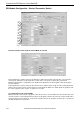

CONFIGURING PID MODULE USING WINDLDR
FC5A MicroSmart PID Module User’s Manual FC9Y-B1283 6-27
OFF
ON
OFF
ON
SP
OFF
ON
SP
OFF
ON
OFF
ON
205203
OFF
ON
197195
OFF
ON
200
205
5
203
OFF
ON
195
200197
Alarm ValueAlarm Value
Alarm Hysteresis
Alarm Hysteresis
Alarm Hysteresis
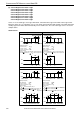
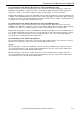
[Setting Example]
: 2.0
Alarm 1 Value
: 205
C
Alarm 1 Hysteresis
C
[Alarm Action]
C205 Process Variable (PV): Alarm Output ON
Process Variable (PV)
203 : Alarm Output OFFC
[Setting Example]
: 2.0
Alarm 1 Value
: 195
C
Alarm 1 Hysteresis
C
[Alarm Action]
C197 Process Variable (PV): Alarm Output OFF
Process Variable (PV)
195 : Alarm Output ONC
2.0
C
C C
C
C
Alarm Hysteresis
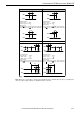
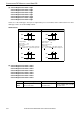
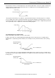
Upper Limit Alarm with Standby Lower Limit Alarm with Standby
[Setting Example]
Set Point (SP)
: 2.0
Alarm 1 Value
: 200 C
: 5
C
Alarm 1 Hysteresis
C
[Alarm Action]
C205 Process Variable (PV): Alarm Output ON
Process Variable (PV)
203 : Alarm Output OFFC
Set Point (SP)
: 2.0
Alarm 1 Value
: 200 C
: -5
C
Alarm 1 Hysteresis
C
[Alarm Action]
[Setting Example]
197
Process Variable (PV) : Alarm Output OFF
Process Variable (PV)
195 : Alarm Output ONC
+Alarm Value-Alarm Value
+Alarm Value-Alarm Value
2.0 C
C
2.0 C
-5
C
C
CCCCC
C
: Standby functions.
Process High Alarm
Process Low Alarm
2.0
C
Note: When the set point (SP) is changed, the standby function is enabled. Once the process variable (PV)
enters the alarm output off range, the standby function is canceled.