
Instruction Manual


APPENDIX
FC5A MicroSmart PID Module User’s Manual FC9Y-B1283 9-9
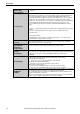
Factory Default Settings of the PID Module
The factory default settings of the parameters of each block are described. Values indicated in
parentheses are stored in the data registers allocated to each block.
Block 1 Write Only Parameters
Offset from
the Control
Register
Parameter
Default Value
CH0
CH1
+20
+23
Set Point (SP)
0°C (0)
+21
+24
Manual Mode Output Manipulated Variable
0% (0)
+22
+25
Operation Parameter *1
0
*1: For details about the operation parameter, see page 5-10.
Blocks 2, 3 Basic Parameters
Offset from
the Control
Register
Parameter
Default Value
CH0
CH1
+26
+103
Proportional Term
Proportional band: 10°C (10)
+27
+104
Integral Time
200 sec (200)
+28
+105
Derivative Time
50 sec (50)
+29
+106
ARW (Anti-Reset Windup)
50% (50)
+30
+107
Control Period
FC5A-F2MR2 (Relay output): 30 sec (30)
FC5A-F2M2 (Non-contact voltage output):
3 sec (3)
+31
+108
Reset
0.0°C (0)
+32
+109
Output Manipulated Variable Rate-of-Change
0%/second (0)
+33
+110
Set Point (SP) Rise Rate
0°C/minute (0)
+34
+111
Set Point (SP) Fall Rate
0°C/minute (0)
+35
+112
Loop Break Alarm (LA) Time
0 minutes (0)
+36
+113
Loop Break Alarm (LA) Span
0°C (0)
+37
+114
Alarm 1 Value
0°C (0)
+38
+115
Alarm 2 Value
+39
+116
Alarm 3 Value
+40
+117
Alarm 4 Value
+41
+118
Alarm 5 Value
+42
+119
Alarm 6 Value
+43
+120
Alarm 7 Value
+44
+121
Alarm 8 Value
+45
+122
Reserved
0
+46
+123
Output Manipulated Variable Upper Limit
100% (100)
+47
+124
Output Manipulated Variable Lower Limit
0% (0)
+48
+125
Cooling Proportional Band (CH0 only)
[CH0] 1.0 times (10)
[CH1] 0
+49
+126
Cooling Control Period (CH0 only)
[CH0]
FC5A-F2MR2 (Relay output): 30 sec (30)
FC5A-F2M2 (Non-contact voltage
output): 3 sec (3)
[CH1] 0
+50
+127
Overlap/Dead Band (CH0 only)
[CH0] 0.0°C (0)
[CH1] 0
+51
+128
Cooling Output Manipulated Variable Upper
Limit (CH0 only)
[CH0] 100% (100)
[CH1] 0
+52
+129
Cooling Output Manipulated Variable Lower
Limit (CH0 only)
[CH0] 0% (0)
[CH1] 0