
Datasheet


62
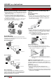
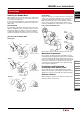
Removing and Installing the Contact Block
1) Turn the locking lever on the contact block in the direction
opposite to the arrow on the housing. Then the contact
block can be removed.
2) Insert the contact block with the TOP markings on the
contact block and the operator placed in the same
direction. Then lock the units, turning the locking lever in
the direction of the arrow.
Note: When removing/installing the contact block, or when using the
contact block alone, do not apply excessive force on the actuator.
Deformed actuator may affect contact operation.
Locking Lever
Actuator
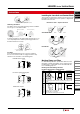
Panel Mounting
Remove the contact block from the operator. Insert the
operator into the panel cut-out from the front, then install the
contact block to the operator.
(For Standard Bezel)
TOP
TOP
Panel
➀
➁
Anti-rotation Ring
Locking Ring
Contact Block
(For Flush Bezel)
TOP
TOP
Panel
➀
Anti-rotation Ring
➁
Locking Ring
Contact Block
Notes on Mounting
Use the optional ring wrench (MT-001) to mount the
operator onto the panel. The recommended tightening
torque is 0.5 to 0.7 N·m. Do not use pliers. Excessive
tightening will damage the locking ring.
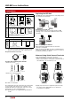
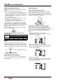
Replacing the Lens and Marking Plate
Removing
[Removing the operator]
Standard Bezel
1) From the opposite side of the TOP marking, remove the
operator (lens, marking plate, and lens holder) using
the optional lens removal tool (MT-101) by gripping the
recesses of the color lens.
Flush Bezel
1) From the opposite side of the TOP marking, push the tip
(width: 3 mm, thickness: 0.5 mm) of the flat screwdriver
to the groove of the color lens and pull out the operator
(lens, marking plate, lens holder).
Note: For metallic bezels, the bezel may be damaged if the
screwdriver is inserted from the TOP side or inserted
deeply or with force into the groove of the lens.
Remove from the
opposite side of
the TOP marking
TOP
[Removing the Operator]
2) Remove the marking plate by pushing the lens from
the rear to disengage the latches between the lens and
holder, using the screwdriver as shown below.
Note: The translucent in the lens holder cannot be removed
because this filter is sealed to make the unit waterproof
and oiltight.
LBW Series Pushbutton (button style)
LBW series pushbuttons (button style, see page 28) can be
removed according to the following procedure. LBW series
pushbuttons (button style) cannot be removed from the front
of the panel.
[Removing the Operator]
1) Detach the operator unit and contact block. (See
Removing and Installing the Contact Block at the top of
the page.)
2) Remove the button unit (button, button holder) by pushing
out the cross-shaped protrusion (white) at the back of the
operator with a screwdriver.
Instructions
LB/LBW Series Instructions