
Datasheet


53
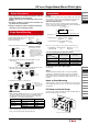
UP series miniature pilot light single board mounting types can be
mounted with LB/ LBW series on the same panel.
Follow the instructions below on
single board mounting.
1. Mount the LED kit to the PC board.
2. Mount the operator and the UP series pilot lights on to the
control panel.
Panel
UP Unit
Operator
3. Mount the contact block to the operator of the miniature control
unit and lock the unit by turning the locking lever.
Contact
Block
Locking Lever
4. Install the PC board in 1. to the panel in 3.
∗
* When mounting LB/LBW and UP series on a single board, make
sure that the distance between the front of the panel and the
mounting side of the PC board (gasket distortion is taken into
consideration) is as shown in the table below.
Part No. Mountable Unit
Distance (*)
UP8-89V1*
Standard bezel 22.5mm
UP8-89V2*
Flush bezel 29.9mm
UP9P-99V1*
Standard bezel 22.5mm
Flush bezel 29.9mm
5. Solder the terminals.
Before soldering, make sure that each terminal of the contact
block is securely inserted into the PC board holes.
LED Kit
UP Unit
• Turn off power to the unit before installation, removal,
wiring, maintenance, and inspection.
Failure to turn off may cause electrical shocks or fire
hazard.
• For wiring, use wires of a proper size to meet the volt-
age and current requirements.
• Improper soldering or failure to tighten the terminal
screw may cause overheating and fire.
Polarity
Pay attention to the polarity of the power supply as UP series units
do not contain a diode for protection against reverse polarity. The
long terminal is positive and the short terminal is negative.
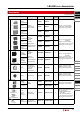
Current Limiting Resistor
When using a UP series unit without a built-in current limiting
resistor, connect an external current limiting resistor. Calculate the
resistance using the following formula.
Current Limiting Resistor
(R)
Operating Voltage
(V)
+
–
LED
Operating Voltage (V) – Forward Voltage (Vf)
Rated Current (I)
*
Resistance
(Ω)
=
* Rated Current (
I) = R (red), W (white) : 0.007A
G (green) : 0.002A
Forward Voltage (Vf) = R (red), W (white) : 2V
G (green) : 2.7V
Note: Use a resistor of higher resistance than the calculated value (Ω)
Rated Wattage
of Resistor (W)
Rated Current
(I)
Operating
Voltage (V)
2 to 3
*= × ×
* 2 to 3 is a safety factor
<Current Limiting Resistor Reference Value>
Color
Operating
Voltage
Red (R), White (W) Green (G)
5V DC 430Ω (1/4W) 1200Ω (1/4W)
6V DC 560Ω (1/4W) 1600Ω (1/4W)
12V DC 1500Ω (1/4W) 4700Ω(1/4W)
24V DC 3000Ω (1/2W) 11000Ω(1/4W)
Countermeasures against Dim Lighting
See page 66.
Wiring
Solder the terminal at 350°C within 3 seconds using a 60W
soldering iron. SnAgCu type lead-free solder is recommended.
When soldering, do not touch the pilot light housing with the
terminal. Do not bend the terminal or apply excessive force to the
terminal.
Notes on Panel Mounting
Tightening torque should not exceed 0.49 N·m. Do not use pliers.
Do not tighten with excessive force, otherwise the locking ring will
be damaged.
PC Board and Circuit Design
Use glass epoxy copper clad laminate, double-sided through-hole
PC boards with a thickness of 1.6 mm.
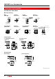
Example of single board mounting
Note: Make sure
that the LED kit is
inserted into the
UP series unit.
Temporary mounting
1. Note the polarity of the
terminals and insert the
terminals to the PC board.
2. Make sure that part A of the
LED kit is pressed tightly
to the PC board. Bend the
terminals sideways as shown
on the left.
Safety Precautions
Single Board Mounting
Instructions
Flush Silhouette
LB Series
Flush Silhouette
LBW Series
ø16
LB Series
UP Series
Illuminated
Pushbutton
Pilot Light
Pushbutton
Selector
Illuminated
Selector
Key Selector
Lever Switch
Buzzer
Accessories
Maintenance
Parts
Panel
Cut-out
Instructions
PC Board
A
Bend terminal
45° minimum
(t=1.6mm)
Insert terminal
UP Series Single Board Mount Pilot Lights