
Data Sheet

For more information, visit http://apac.idec.com
M-019
APEM
Switches &
Pilot Lights
Control Boxes
Emergency
Stop Switches
Enabling
Switches
Safety Products
Explosion Proof
Terminal Blocks
Relays & Sockets
Circuit
Protectors
Power Supplies
LED Illumination
Controllers
Operator
Interfaces
Sensors
AUTO-ID
Sensors
SA1E
SA1E-L
SA1E Miniature Photoelectric Switches (Built-in Amplier)
Power Supply and Wiring
• Do not use the SA1E photoelectric switch at the transient status
immediately after turning on the power (approx. 100 ms, back ground
suppression model: 200 ms). When the load and switch use different
power supplies, make sure to power up the switch rst.
• Use a power supply with little noise and inrush current, and use the
photoelectric switch within the rated voltage range. Make sure that
ripple factor is within the allowable limit. Do not apply AC volt age,
otherwise the switch may blow out or burn.
• When using a switching power supply, make sure to ground the FG
(frame ground) terminal, otherwise high-frequency noise may affect
the photoelectric switch.
• Turn power off before inserting/removing the connector on photo-
electric switch. Make sure that excessive mechanical force is not
applied to the connector. Connect the connector cable to a tight ening
torque of 0.5 N·m maximum.
• To ensure the degree of protection, use the applicable connector
cable for the connector model. Connector cables are ordered sepa-
rately.
• Avoid parallel wiring with high-voltage or power lines in the same
conduit, otherwise noise may cause malfunction and damage. When
wiring is long, use a separate conduit for wiring.
• Use a cable of 0.3 mm
2
minimum core wires, then the cable can be
extended up to 100m.
Installation
Installing the Photoelectric Switch
• Do not install the SA1E photoelectric switches in an area where
the switches are subject to the following conditions, otherwise
malfunction and damage may be caused.
∗ Inductive devices or heat source
∗ Extreme vibration or shock
∗ Large amount of dust
∗ Water, oil, chemicals
∗ Outdoor
• Make sure to prevent sunlight, uorescent light, and especially
the uorescent light of inverters from entering the receiver of the
photoelectric switch directly. Keep the through-beam model receiver
away from intense extraneous light.
• Interference prevention allows two SA1E switches to be mounted in
close proximity. However, the through-beam model is not equipped
with interference prevention. Maintain appropriate dis tance between
the switches referring to the lateral displacement characteristics.
• Because the SA1E photoelectric switches are IP67 waterproof, the
SA1E can be exposed to water. However, wipe water drops and
smears from the lens and slit using a soft cloth to make sure of the
best detecting performance.
• Polycarbonate or acrylic resins are used for optical elements. Do not
use ammonia or caustic soda for cleaning, otherwise optical elements
will be dissolved. To remove dust and moisture build-up, use soft dry
cloth.
• Tighten the mounting screws (M3) to a torque of 0.5 N·m. Do not
tighten the mounting screws excessively or hit the switch with a
hammer, otherwise the protection degree cannot be maintained.
Installing the Reflector
• Use M4 mounting screws for the IAC-R5 and IAC-R8 reector, and
M3 mount ing screws for the IAC-R6 reector. Tighten the mounting
screws to a tightening torque of 0.5 N·m maximum. Mounting screws
are not supplied with the switch.
• Use the M3 self-tapping screw, at washer, and spring washer to
tighten the IAC-R7 reector to a torque of 0.5 to 0.6 N·m.
• Optional reector mounting bracket IAC-L2 is not supplied with
mounting screws or nuts.
• IAC-L3 and IAC-L5 are supplied with mounting screws for mounting
the reector on the bracket.
• Reector IAC-RS1 and IAC-RS2 can be installed directly on a at
surface using the adhesive tape attached to the back of the reec-
tor. Before attaching the reector, clean the board surface to ensure
secure attachment.
Installing the air blower mounting block SA9Z-A02
• When installing the SA9Z-A02 on the SA1E photoelectric switch, use
the attached M3 × 20 mounting screws and tighten to a torque of 0.5
N·m maximum.
• Do not use the mounting screw (M3 × 12) supplied with the mount ing
bracket (SA9Z-K01) to mount the SA1E photoelectric switches.
• The SA9Z-A02 cannot be used with the through-beam slits
(SA9Z-S06 to S14).
• The air tube tting (M5) can be installed to either the top or side. The
air tube is not supplied.
• Close the unused port using the air supply port plugging screw and
gasket (supplied with SA1E) to a tightening torque of 1 to 2 N·m
maximum. The recommended air pressure is 0.1 to 0.3 MPa.
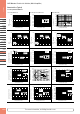
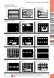
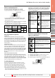
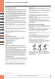
Installing the background suppression (BGS) model
• This sensor can detect objects correctly when the sensor head is
installed perpendicular to the moving object. Install the sensor head
as shown below to minimize sensing errors.
Correct
Object Object Object
Correct Incorrect
• If the sensor is used in a place subject to a large variations in the
ambient temperature, the characteristics may change depending on
the target object. Be sure to check the operation under the actual
operating conditions.
Operating Instructions
SEUEN01A_M SA1E June 2021
For more information, visit http://eu.idec.com