
Data Sheet

Download catalogs and CAD from http://apac.idec.com
M-018
APEM
Switches &
Pilot Lights
Control Boxes
Emergency
Stop Switches
Enabling
Switches
Safety Products
Explosion Proof
Terminal Blocks
Relays & Sockets
Circuit
Protectors
Power Supplies
LED Illumination
Controllers
Operator
Interfaces
Sensors
AUTO-ID
Sensors
SA1E
SA1E-L
SA1E Miniature Photoelectric Switches (Built-in Amplier)
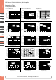
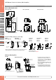
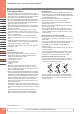
Indicator and Output Operation
(except for background suppression model)
• The operation LED turns on (yellow) when the control output is on.
Operation LED (yellow)
Stable LED (green)Sensitivity Control
• The stable LED turns on (green) either at stable incident or stable
interruption. Make sure to use the photoelectric switch after the
stable operation is ensured.
• In the light ON operation, the output turns on when the receiving light
intensity level is 1.0 or over as shown on the right.
• In the dark-ON operation, the output turns on when the receiving light
intensity level is 1.0 or less as shown on the right.
Receiving Light
Intensity Level
Light Receiving
Status
Stable LED
(green)
Operation LED (yellow)/
Control Output
Light ON Dark ON
Operation
Level
1.2 and over Stable Incident ON
ON OFF
1.0
Unstable Incident
OFF
Unstable Interruption
OFF ON
0.8 and below Stable Interruption ON
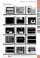
Optical Axis Alignment (Light ON)
Through-beam
Fasten the receiver temporarily. Place the projector to face the
receiver. Move the projector up, down, right and left to find the range
where the operation LED turns on. Fasten the projector in the middle of
the range. Next, move the receiver up, down, right and left in the same
manner and fasten in the middle of the range where the operation LED
turns on. Make sure that stable LED turns on at stable incident and
stable interruption.
Polarized retro-reflective
Install the reflector perpendicularly to the optical axis. Move the SA1E
photoelectric switch up, down, right and left to find the range where
the operation LED turns on. Fasten the switch in the middle of the
range. Polarized retro-reflective model can be installed also by finding
the position where the reflection of projected red light is most intense,
while observing the reflection on the reflector from behind the switch.
Make sure that stable LED turns on at stable incident and stable
interruption.
Diffuse-reflective/Small-beam reflective
Place the SA1E photoelectric switch where the switch can detect the
object. Move the switch up, down, right and left to find the range where
the operation LED tuns on. Fasten the switch in the middle of the
range. Make sure that stable LED turns on at stable incident and stable
interruption. Because the light source element of small-beam reflective
model is a red LED, visual inspection is possible as well.
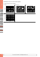
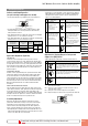
Sensitivity Adjustment
Referring to the table at right, adjust the sensitivity of the SA1E
photoelectric switch when necessary, in such cases as the through-
beam model is used to detect small or translucent objects or the
reflective model is affected by background. The table explains the
status of operation LED when the operation mode is set to light ON.
• After adjusting the sensitivity, make sure that stable LED turns on at
stable incident and stable interruption. For detecting objects too small
to turn on the stable LED, use an optional slit.
• Sensitivity is set to the maximum (+) at the factory before shipment.
When adjusting the sensitivity, use the screwdriver supplied with the
SA1E photoelectric switch to turn the control as shown below, to a
torque of 0.05 N·m maximum.
Step
Photoelectric
Switch Status
Sensitivity
Control
Adjusting Procedure
1
Receiving light
• Through-beam, polarized
reective: No object
detected
• Diffuse reective, small-
beam reec tive:
Object detected
A
Turn the control counter-clockwise
to the mini mum (–). Then turn clock-
wise (toward +) until the operation
LED turns on (turns off with dark ON
type) (point A).
2
Light is interrupted
• Through-beam, polarized
reective: Object detected
• Diffuse reective, small-
beam reec tive:
No object detected
B
A
At interruption status, turn the
control clock wise (toward +) from
point A, until the operation LED turns
on (turns off with dark ON type)
(point B).
If the operation LED does not turn
on (turn off with dark ON type) even
though the control has reached the
maxi mum (+), set the maximum
position (+) as point B.
3 —
C
B
A
Set the middle point between point A
and B as point C.
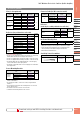
Adjustment of Sensing Range for Background
Suppression (BGS) Model
• When adjusting the sensing range, follow the instruction below.
Step Distance Control Adjusting Procedure
1
A
Install the photoelectric switch and the object rmly. Turn the
control counterclockwise until the operation LED turns off
(turns on with dark ON type). From this point, turn the con trol
clockwise until the operation LED turns on (turns off with dark
ON type) (point A).
2
A
B
Remove the object, and conrm that the operation LED turns
off (turns on with dark ON type). Turn the control clockwise until
the operation LED turns on (detecting the back ground) (turns
off with dark ON type) (point B). (Note 1)
3
A
B
C
Set the middle point between point A and B as point C. (Note 2)
Note 1: When the background is far off and not detected, turn the control 360°,
and set the point as point C.
Note 2: Because the control is multi-turn, it may take more than one turn to
move from point A to point B.
Note 3: Turning the control clockwise lengthens the sensing dis tance.
Note 4: Background suppression (BGS) model is not provided with a stable LED.
Operation LED (yellow)
(Note 3)
Sensing Range Control
(6-turn)
(Note 4)
Operating Instructions
Download catalogs and CAD from http://eu.idec.com/downloads