
Datasheet


7
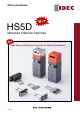
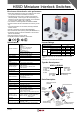
HS5D Miniature Interlock Switches
Instructions
Regardless of door types, do not use the interlock switch •
as a door stop. Install a mechanical door stop at the end
of the door to protect the interlock switch against exces-
sive force.
Do not apply excessive shock to the interlock switch when •
opening or closing the door. A shock to the interlock switch
exceeding 1,000 m/s
2
may cause damage to the interlock
switch.
Do not open the lid of the interlock switch. Loosening the •
screws may cause damage to the interlock switch.
Prevent foreign objects such as dust and liquids from •
entering the interlock switch while connecting a conduit or
wiring.
Plug the unused actuator entry slot using the slot plug •
supplied with the interlock switch.
Use proprietary actuators only. When other actuators are •
used, the interlock switch may be damaged.
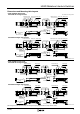
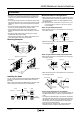
Mounting Examples
Door Stop
Door
HS9Z-A51
Actuator
Application on Sliding Doors
HS5D
Interlock
Switch
HS5D
Interlock
Switch
Door
HS9Z-A52 Actuator
Application on Hinged Doors
HS9Z-SH5 Sliding Actuator
Installing the Head
Do not use the plastic and metal head of the HS5B interlock
switches and metal head of the HS5E interlock switch on
the HS5D.
When using these HS5D and HS5E interlock switches adja-
cently, ensure that the heads are not interchanged.
(black)
Plastic
(red)
HS5EHS5D
Metal HeadMetal HeadPlastic Head
Metal
(silver color)
(red)
HS5B
Plastic Head
Metal
Metal Head
(gray)
Plastic
(black or gray)
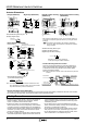
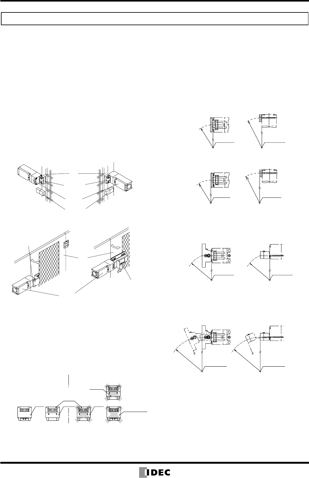
Minimum Radius of Hinged Door
When using the interlock switch for a hinged door, refer to •
the minimum radius of doors shown below. For the doors
with small minimum radius, use angle adjustable actua-
tors (HS9Z-A55).
Note: Because deviation or dislocation of hinged door may occur
in actual applications, make sure of the correct operation
before installation.
When using the HS9Z-A52 Actuator
When the door hinge is on the extension line of the inter- •
lock switch surface:
Door Hinge
Minimum
Radius
190 mm
Door Hinge
Minimum
Radius
170 mm
When the door hinge is on the extension line of the actua- •
tor mounting surface:
Minimum Radius
230 mm
Minimum Radius
260 mm
Door Hinge Door Hinge
When using the HS9Z-A55 Angle Adjustable Actuator
When the door hinge is on the extension line of the inter- •
lock switch surface:
Door Hinge
Door Hinge
Minimum Radius
50 mm
M
inimum Radius
50 mm
Horizontal Swing Vertical Swing
When the door hinge is on the extension line of the actua- •
tor mounting surface:
Door Hinge
Door Hinge
Minimum Radius
50 mm
Minimum Radius
70 mm
Horizontal Swing Vertical Swing
Actuator Angle Adjustment for the HS9Z-A55
Using the angle adjustment screw, the actuator angle can •
be adjusted (see gures on page 6). Adjustable angle: 0
to 20°
The larger the adjusted angle of the actuator, the smaller •
the applicable radius of the door opening. After installing
the actuator, open the door. Then adjust the actuator so
that its edge can be inserted properly into the actuator
entry slot of the interlock switch.
After adjusting the actuator angle, apply Loctite to the •
adjustment screw so that the screw will not loosen.
(100405)