
Datasheet


6
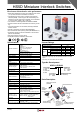
HS5D Miniature Interlock Switches
Safety Precautions
In order to avoid electric shock or re, turn the power off •
before installation, removal, wire connection, mainte-
nance, or inspection of the interlock switch.
If relays are used in the circuit between the interlock •
switch and the load, use only safety relays, since welded
or sticking contacts of standard relays may invalidate the
functions of the interlock switch. Perform risk assessment
and make up a safety circuit which satises the require-
ments of the safety category.
For wiring, use wires of a proper size to meet the voltage •
and current requirements. Tighten the terminal screws to
a recommended torque of 0.6 to 0.8 N·m. Improper sol-
dering or failure to tighten the terminal screw may cause
overheating and re.
Do not place a PLC in the circuit between the interlock •
switch and the load. Safety security can be endangered in
the event of a malfunction of the PLC.
Do not install the actuator in the location where a human •
body may come in contact. Otherwise injury may occur.
Do not disassemble or modify the interlock switch, other- •
wise a malfunction or an accident may occur.
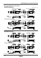
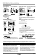
Actuator Dimensions
26
15
32.4
28
20
2.24-R
10
0.85.2
(
6)
6.2
6.4
2
20
2-M4 Screw
Actuator Stop (Note)
15
Actuator Cover
2
2-ø4.4
20
33
30
28
0.84.5
27.2
7.2
1.6
Actuator Stop (Note)
30
7.3 43.8
15.3
15
2-ø4.3
2
12∗
0.8
(20)
0.8
2-ø10
2-ø9
(5)
Ⓑ
Actuator Stop
(Note)
Washer (supplied with the actuator)
Rubber Bushing
30
15
15.8
8.5
0.8
2
0.8
(11.2)
(39.7)
(
5
)
2-ø9
2-ø10
2-ø4.3
12∗
(
20
)
Washer (supplied
with the actuator)
Rubber Bushing
Actuator Stop (Note)
A
B
49
15
7
18.5
29
3
3.6
1
R2.1
23
26
38
0.8
2
20º
20º
Horizontal Swing
Angle Adjustment
(M3 Hexagon Socket Head Screw)
Actuator Stop
(Note)
(M4 Holes)
Vertical Swing
Orienting
Insert
Orienting
Insert
Actuator Stop
(Note)
Angle Adjustment
(M3 Hexagon Socket Head Screw)
Interlock Switch
Actuator Stop
HS9Z-A51 Actuator
Door Stop
Door Stop
Interlock Switch
Actuator
Stop
Actuator
Cover
Interlock Switch
Actuator Stop
HS9Z-A52 Actuator HS9Z-A55 Actuator
Straight (HS9Z-A51) • Right-angle (HS9Z-A52) • Straight w/rubber bushing •
(HS9Z-A51A)
Right-angle w/rubber bushing •
(HS9Z-A52A)
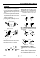
Angle Adjustable (HS9Z-A55) •
Actuator Orientation (Angle Adjustable) •
The angle of actuator swing can be changed using the orienting insert (white plastic) installed on the back of the actuator.
Do not lose the orienting insert, otherwise the actuator will not operate properly.
Note: The actuator stop is supplied with the actuator and used
when adjusting the actuator position. Remove the actuator
stop after the actuator position is determined.
*The mounting center distance is set to 12 mm at factory. When 20-
mm distance is required, adjust the distance by moving the rubber
bushings.
*Mounting centers can be widened to
20 mm by moving the rubber
cushions.
12
2-M4 Screw
Actuator Mounting Hole Layout
(Straight w/rubber bushing)
(Right-angle w/rubber bushing)
Actuator Mounting Hole Layout
(Straight, Right-angle)
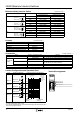
Actuator Mounting Reference Position •
As shown in the gure below, the mounting reference po-
sition of the actuator when inserted in the interlock switch
is where the actuator stop placed on the actuator lightly
touches the interlock switch.
Actuator Mounting Hole Layout •
(horizontal/vertical swing)
38
2-M4 Screw
: The actuator has exibility to the directions indicated by
the arrows. When 20-mm distance is selected, the actuator
swings vertically.
A B
Note: After mounting the actuator, remove the actuator stop from the
actuator.
(100405)