
User guide

Chapter 2
58
External Device Setup Manual
2.2 System Configuration
This is the system configuration for the connection of Mitsubishi PLCs to the MICRO/I.
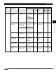
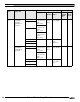
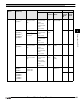
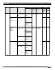
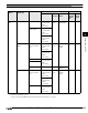
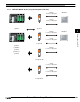
2.2.1 MELSEC-A Series (using the Computer Link Unit)
RS232C MICRO/I
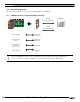
Connection Diagram 1
RS485
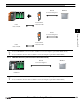
Connection Diagram 2
A1N, A2N, A3N AJ71C24
AJ71C24-S3
A1N, A2N, A3N
A2A, A3
AJ71C24-S6
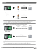
AJ71C24-S8
A1N, A2N, A3N
A2A, A3A
A2U, A3U, A4U
AJ71UC24
AQJ2, A0J2H A0J2-C214-
S1
- In case of HG2F/3F/4F a connection cable is available for Connection Diagram 1 (part number: HG9Z-3C135).
- In case of HG1F a connection cable is available for Connection Diagram 1 (part number: HG9Z-XC145).