
User guide

621
1 Modbus
5
5
5
5
5
5
5
5
5
5
5
5
5
5
5
Modbus
External Device Setup Manual
1.6.6 Communication Format
This chapter describes the communication format of the Modbus TCP Server communication.
The Modbus TCP Server communication supports Class 0 and Class 1 functions of the OPEN Modbus TCP SPECIFICATION
Release1.0. For details about the communication methods, refer to the OPEN Modbus TCP SPECIFICATION Release1.0 as well as
this manual.
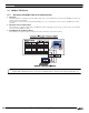
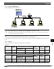
1. Preparations for Communication
The Modbus TCP Server performs communications using the TCP. Make sure to establish a connection with the specified port of the MICRO/I or
Touch with TCP before executing reading/writing of devices.
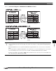
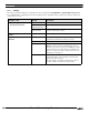
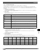
2. Basic Format
The following table lists the basic format of communications. The same format applies to both requests and responses.
Data is processed as a byte sequences.
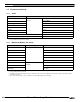
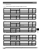
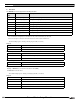
3. Reference Numbers
Reference numbers are used to specify a device address with the Modbus TCP.
The reference number is obtained by subtracting 1 from the 1st to 5th value of the device address, and is expressed in hexadecimal format.
The following table lists the address of each device and the corresponding reference number.
Byte Description
Byte 0
Transaction ID
*1
. The same value is returned from the server. The value is normally “0”.
*1. The data included in a request is returned from the server without changes. The client (external device) sends a different Transaction ID for
each request, and identifies the response by checking the Transaction ID of a response. Enter “0” to not check the Transaction ID.
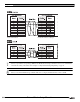
Byte 1
Transaction ID
*1
. The same value is returned from the server. The value is normally “0”.
Byte 2
Protocol ID
*2
. The value is always “0”.
*2. The number indicating the Modbus TCP protocol, and is always “0”.
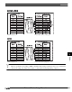
Byte 3
Protocol ID
*2
. The value is always “0”.
Byte 4
Message length
*3
(high byte). The value is always “0”. (Since the message is 256 bytes at maxi-
mum.)
*3. Indicates the length of the following message in units of bytes.
Byte 5
Message length
*3
(low byte). The length of the following message.
Byte 6
Unit ID
*4
*4. ID used for identifying devices. The ID is not used with the MICRO/I or Touch. When the ID is used in a request, the returned data is
unchanged.
Byte 7
Function code
*5
*5. Numbers assigned for functions such as reading and writing.
Byte 8-
Data
*6
*6. Data required for each processing.
Address Reference
No.
Address Reference
No.
Address Reference
No.
Address Reference
No.
C 1 0001 I 100001 0001 HR 400001 0001 IR 300001 0001
C 2 0002 I 100002 0002 HR 400002 0002 IR 300002 0002
……………………
C 65535 FFFE I 165535 FFFE HR 465535 FFFE IR 365535 FFFE
C 65536 FFFF I 165536 FFFF HR 465536 FFFF IR 365536 FFFF