
User guide

619
1 Modbus
5
5
5
5
5
5
5
5
5
5
5
5
5
5
5
Modbus
External Device Setup Manual
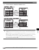
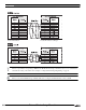
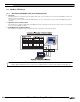
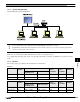
1.6.2 System Configuration
The following is the system configuration.
1.6.3 Wiring
Make sure to use commercially available 10BASE-T ready cables for connecting the devices.
Use a straight cable when using a hub, and use a crossing cable when directly connecting to the MICRO/I or Touch and an external
device.
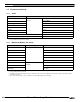
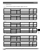
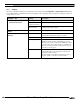
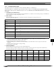
1.6.4 Devices
The following devices are available for Modbus TCP Server communication.
All devices are general-purpose devices intended for nonspecific purposes.
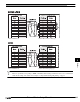
- Up to 4 external devices can communicate with a single MICRO/I or Touch unit at one time.
- The MICRO/I or Touch unit and an external device can be directly connected on a 1:1 basis by bypassing a hub. In this
case, use a crossing cable for the connection.
Bit Device
Device Name Device
Symbol
Address Range MICRO/I or
Touch
Read/Write
External
Device
Read/Write
Address
Gradual
HG2G-S/-5S/-5F,
HG3G/4G, Touch
HG1F/2F/2S/3F/4F
Coil Status C 1 - 4096 1 - 65536 R/W R/W Decimal
Input Status I 100001 - 104096 100001 - 165536 R/W R Decimal
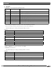
Word Device
Device Name Device
Symbol
Address Range MICRO/I or
Touch
Read/Write
External
Device
Read/Write
Address
Gradual
HG2G-S/-5S/-5F,
HG3G/4G, Touch
HG1F/2F/2S/3F/4F
Holding Register HR 400001 - 404096 400001 - 465536 R/W R/W Decimal
Input Register IR 300001 - 304096 300001 - 365536 R/W R Decimal