
User guide


Chapter 4
576
External Device Setup Manual
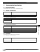
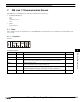
6 DM Link Communication Settings
The settings required in WindO/I-NV2 or WindO/I-NV3 for the using the DM Link communication are located in the Configura-
tion - System Setup - Project dialog box. (Refer to 1.3 and 1.4 in Chapter 2 of the WindO/I-NV2 User’s Manual or SmartAXIS
Touch User's Manual. Set the items in the following table in accordance with the external device that you will be using.
Dialog Box Name
- Tab Name
Setting Name Description
Project Settings -
Host I/F Driver or
Communication
Driver
Manufacturer Select IDEC HG System or IDEC System.
Host I/F Driver
Communication Driver
Select DM Link 1:1 for DM Link 1:1 communication and DM Link 1:N for
DM Link 1:N Communication.
Transmission Wait Set the time after which the MICRO/I or Touch sends a response command
to the external device after receiving a command from the external device.
The actual time until the response is sent is greater than the Transmission
wait time and less than the Transmission wait time +10msec.
Retry Cycles This setting is not required.
Time Out
With BCC Select the checkbox if you want to perform BCC checking.
Max Event Transmission
Words (Only DM Link 1:1)
Set the max number of words for event transmission.
Protocol
(Only DM Link 1:1)
Select the number of protocol format.
0: Basic protocol format
1: Protocol format 1(Add an error code and “CR” to “ACK”, “NAK” in
Basic protocol format.)
DM LINK No.
(Only DM Link 1:N)
Set the DM Link station number.
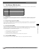
Project Settings -
Communication
Interface
Protocol Select Host Communication.
Baud Rate Select the same setting used for the external device.
(1200, 2400, 4800, 9600, 19200, 38400, 57600 or 115200bps)
Data Bits Select the same setting used for the external device. (7 or 8 bits)
Stop Bits Select the same setting used for the external device (1 or 2 bits)
Parity Select the same setting used for the external device. (Even, Odd or None)
Serial Interface Select the serial interface that you will be using.
(RS232C, RS422/485 2-wire or RS422/485 4-wire)
Flow Control Select either Hardware or None.
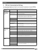
Project Settings -
System
Start Time Set this to 0.
Use System Area Select this if you want to use the system area.
Device Specify the system area start Device address.
Use System Areas 3, 4 Select this if you want to use the system areas 3 and 4.
Watch Dog If you select Watch Dog, set the Write Device and the Time (write interval).
If you will transmit from the MICRO/I or Touch to the external device, set a
write device for the event output area.
Device
Time