
User guide

533
21 VIGOR
2
2
2
2
2
2
2
2
2
2
2
2
2
2
2
Connection to a PLC
External Device Setup Manual
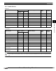
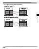
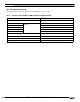
21.5 Usable Devices
Device Address 992 in Step Relay (Word) only contains 8bits because the maximum device address of Step Relay (Bit) is
999.
Bit Device
Device Name Device Symbol Address Range Read
/Write
Address
Gradual
MICRO/I PLC
Input Relay(Bit) X X 0 - 777 R OCT
Output Relay(Bit) Y Y 0 - 777 R/W OCT
Auxiliary Relay(Bit) M M 0 - 5119 R/W DEX
Step Relay S S 0 - 999 R/W DEX
Special Relay SM M 9000 - 9255 R/W DEX
Timer Contact T T 0 - 255 R DEX
Timer Coil TC T 0 - 255 R DEX
Counter Contact C C 0 - 255 R DEX
Counter Coil CC C 0 - 255 R DEX
Word Device
Device Name Device Symbol Address Range Read
/Write
Address
Gradual
MICRO/I PLC
Input Relay(Word) WX X 0 - 769 R OCT
Output Relay(Word) WY Y 0 - 760 R/W OCT
Auxiliary Relay(Word) WM M 0 - 5104 R/W DEX
Step Relay(Word) WS S 0 - 992 R/W DEX
Special Relay(Word) WSM M 9000 - 9240 R/W DEX
Data Registor T D 0 - 8191 R/W DEX
Special Registor SD D 9000 - 9255 R/W DEX
Timer Current Value TCV T 0 - 255 R/W DEX
16 Bit Counter
Current Value
CCV C 0 - 199 R/W DEX
32 Bit Counter
Current Value
DCCV C 2000 - 2551 R/W DEX