
User guide

515
21 VIGOR
2
2
2
2
2
2
2
2
2
2
2
2
2
2
2
Connection to a PLC
External Device Setup Manual
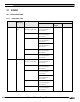
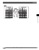
21.2 System Configuration
This is the system configuration for the connection of VIGOR PLCs to the MICRO/I.
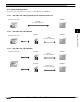
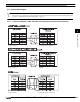
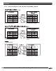
21.2.1 VB0, VB1, VB2, VH (Programming Tool Communication Port)
21.2.2 VB0, VB1, VB2, VH (VB-485A)
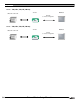
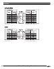
21.2.3 VB0, VB1, VB2, VH (VB-CADP)
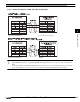
VB0, VB1, VB2, VH MICRO/I
RS232C
Connection Diagram 1
VB0, VB1, VB2, VH
VB-485A MICRO/I
RS485
Connection Diagram 2
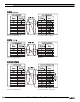
VB0, VB1, VB2, VH VB-CADP MICRO/I
RS232C
Connection Diagram 3
VB-CADP MICRO/I
RS485 2-wire
Connection Diagram 4