
User guide

479
19 Toshiba
2
2
2
2
2
2
2
2
2
2
2
2
2
2
2
Connection to a PLC
External Device Setup Manual
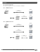
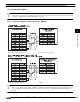
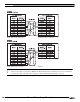
19.3 Connection Diagram
The connector types given in the Connection Diagrams are for the unit and not the cable. For details regarding wiring, refer
to Chapter 1 "3 Important Points Regarding Wiring" on page 19.
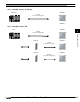
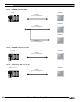
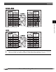
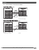
19.3.1 Connection Diagram 1: RS485 D-sub 15P - MICRO/I
There is no pin number corresponding to TERM on the HG2G-S/-5S/-5F, HG3G/4G. When inserting a termination resistor,
use a communication switch. For the setting of the switch, refer to Chapter 1 "3 Important Points Regarding Wiring" on
page 19.
D-sub, 15P connector socket type D-sub, 9P connector plug type
D-sub, 15P connector socket type Terminal