
User guide

435
17 INVERTER
2
2
2
2
2
2
2
2
2
2
2
2
2
2
2
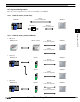
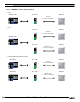
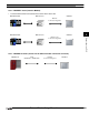
Connection to a PLC
External Device Setup Manual
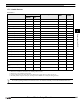
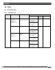
17.5 Usable Devices
For details regarding parameters and write data, refer to the instruction manual provided with the Mitsubishi inverter.
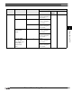
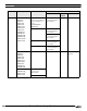
Word Device
Device Name Device Symbol Address Range Read
/Write
Address
Gradual
MICRO/I PLC
Parameter P P 0 - 999 R/W
Parameter 37 P37 P 0 - 1 R/W
*1*2
*1. Use this device for parameter 37.
*2. This device is handled as a 32-bit device by combining addresses 0 and 1.
Operation mode OP OP 0 R/W
Output frequency OF OF 0 R
*3
*3. This Device is only available for 4 digits data.
Output current OC OC 0 R
Output voltage OV OV 0 R
Alarm description (1, 2) E12 E12 0 R
Alarm description (3, 4) E34 E34 0 R
Alarm description (5, 6) E56 E56 0 R
Alarm description (7, 8) E78 E78 0 R
Run command RC RC 0 R/W
*4
*4. Only the write data becomes valid on this device. When used for display, the device always becomes “0”.
Inverter status monitor ISM ISM 0 R
Set frequency read (RAM) SFRR SFRR 0 R
*3
Set frequency read (E2PROM) SFRE SFRE 0 R
*3
Set frequency write (RAM) SFWR SFWR 0 R/W
*3
*4
Set frequency write (E2PROM) SFWE SFWE 0 R/W
*3
*4
Inverter reset IR IR 0 R/W
*4
Alarm definition batch clear EC EC 0 R/W
*4
All parameter clear PACL PACL 0 R/W
*4
Link parameter expansion set-
ting
LPES LPES 0 R/W
*5
*5. The Link parameter expansion setting may be changed from the MICRO/I for reading and writing parameters.
Second parameter changing SPC SPC 0 R/W