
User guide

415
16 YOKOGAWA
2
2
2
2
2
2
2
2
2
2
2
2
2
2
2
Connection to a PLC
External Device Setup Manual
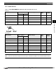
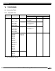
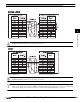
16.2 System Configuration
This is the system configuration for the connection of YOKOGAWA PLCs to the MICRO/I.
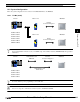
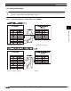
16.2.1 FA-M3 (Serial)
We recommend F3LC11-2N side to carry a “4-WIRE” setup of the terminus resistance (TERMINATOR) in long-distance
transmission.
It connects with the port for programming tools of a CPU unit.
It does not correspond to “CPU direct connection system” of F3SP20 and F3SP30.
FA-M3 F3LC11-1N MICRO/I
RS232C
Connection Diagram 1
F3SP05, F3SP20,
F3SP21, F3SP25, F3LC11-2N MICRO/I
F3SP30, F3SP35,
F3SP38, F3SP53, RS485
Connection Diagram 2
F3SP58, F3FP36,
F3BP20, F3BP30,
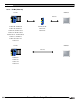
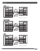
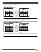
FA-M3 YOKOGAWA cable RS232C MICRO/I
KM10-0C Connection Diagram 3
YOKOGAWA cable
KM11-2N*A
F3SP05, F3SP21,
F3SP25, F3SP28,
F3SP35, F3SP38,
F3SP53, F3SP58,