
User guide

399
14 Koyo
2
2
2
2
2
2
2
2
2
2
2
2
2
2
2
Connection to a PLC
External Device Setup Manual
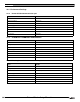
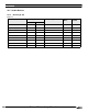
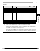
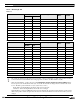
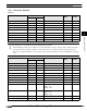
Word Device
Device Name Device Symbol Address Range Read
/Write
Address
Gradual
MICRO/I PLC
Input Points (Word) XW V 40400 - 40477 R 8 (octal)
Output Points (Word) YW V 40500 - 40577 R/W 8 (octal)
Control Relays (Word) CW V 40600 - 40777 R/W 8 (octal)
Stages (Word) SW V 41000 - 41077 R/W 8 (octal)
Remote In (Word) GXW V 40000 - 40177 R/W 8 (octal)
Remote Out (Word) GYW V 40200 - 40377 R/W 8 (octal)
Special Relays (Word) SPW V 41200 - 41237 R 8 (octal)
Timer Values TV V 0 - 377 R/W 8 (octal)
Counter Values CV V 1000 - 1377 R/W 8 (octal)
Data Registers D V 1400 - 7377 R/W 8 (octal)
System Parameters1 SR1 V 700 - 777 R 8 (octal)
System Parameters2 SR2 V 7400 - 7777 R 8 (octal)
Ext Registers ER V 10000 - 37777 R/W 8 (octal)
- We confirm only D4-440 address range. Depending on the type of PLC that you will be using, the there are limits to the
areas that can be used within the device ranges given above. Refer to the PLC manual for details.
- When selecting Bit Write, operation depends on the Configuration-System Setup-Project-Host I/F Driver which
have an option to turn off all other bits in the byte or leave all other bits without change. Check or unchecked the check
box for “Bit Write operation will write to a byte.” (Byte refers to 8 bits.)
Check: When executing Bit Write, all other bits in the byte are turned off.
Unchecked: When executing Bit Write, all other bits are not changed.
During Bit Write operation, the MICRO/I reads the byte data including the designated bit from the PLC, performs logical
AND or OR operation with the designated bit, and writes the result into the PLC, therefore all other bits in the byte are not
changed.