
User guide

365
12 Panasonic Electric Works
2
2
2
2
2
2
2
2
2
2
2
2
2
2
2
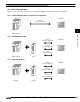
Connection to a PLC
External Device Setup Manual
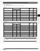
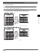
12.5 Usable Devices
Types of devices supported by the MICRO/I and their ranges are shown below.
The device ranges may differ depending on the PLC model. Please refer to PLC Manual for supported memory ranges of
the PLC.
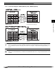
Bit Device
Device Name Device Symbol Address Range Read
/Write
Address
Gradual
MICRO/I PLC
Input X X 0 - 511F R
*1
*1. 3 figures of higher ranks are expressed by decimal, and 1 figure of low ranks is expressed by hexadecimal.
Output Y Y 0 - 511F R/W
*1
Internal Relay R R 0 - 886F R/W
*1
Special Internal relay RE R 9000 - 910F R
*1
Link Relay L L 0 - 639F R/W
*1
Timer TT0 - 3071 RDec
Counter C C 0 - 3071 R Dec
Error alarm relay E E 0 - 2047 R Dec
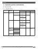
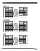
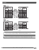
Word Device
Device Name Device Symbol Address Range Read
/Write
Address
Gradual
MICRO/I PLC
Input WXWX0 - 00511 R Dec
Output WY WY 0 - 00511 R/W Dec
Internal Relay WR WR 0 - 00886 R/W Dec
Special Internal relay WRE WR 900 - 00910 R Dec
Link Relay WL WL 0 - 00639 R/W Dec
Timer, Counter (Elapsed value) EV EV 0 - 03071 R Dec
Timer, Counter (Set value) SV SV 0 - 03071 R/W Dec
Data register DT DT 0 - 99999 R/W Dec
Link data register LD LD 0 - 08447 R/W Dec
File register FL FL 0 - 32764 R/W
Dec
*1
*1. In FP2SH, the contents of a bank 0 are written.