
User guide

Chapter 2
340
External Device Setup Manual
12 Panasonic Electric Works
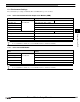
12.1 Connection Table
12.1.1 Compatible Protocols
Series Name System
(CPU unit)
Link Unit WindO/I-NV2 Settings
Interface Flow Control Host I/F Driver
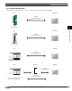
FP Series FP0
Not required
*1
(Connects to CPU unit directly)
RS232C
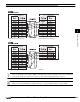
Connection Diagram 1
(refer to P344)
Hardware MEWNET
FP1
*1
*1. We tested with the PLC of these parts.
Not required
(Connects to RS232C Port)
RS232C
Connection Diagram 2
(refer to P346)
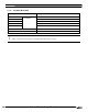
Not required
(Connects to CPU unit directly)
RS232C (AFP8550)
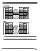
Connection Diagram 3
(refer to P348)
Not required
*1
(Connects to CPU unit directly)
RS422/485 4-wire
Connection Diagram 4
(refer to P351)
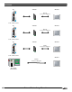
FP
*1
Not required
*1
(Connects to CPU unit directly)
RS232C
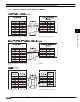
Connection Diagram 1
(refer to P344)
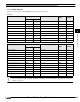
Used Communication cassette
AFPG801
*1
RS232C
Connection Diagram 5
(refer to P354)
Used Communication cassette
AFPG802
*1
RS232C
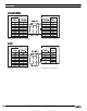
Connection Diagram 6
(refer to P356)
Used Communication cassette
AFPG803
*1
RS422/485 2-wire
Connection Diagram 7
(refer to P358)
FP10,
FP10SH
Not required
*1
(Connects to Tool Pot or Com
Port)
RS232C
Connection Diagram 8
(refer to P361)
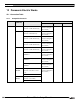
AFP3462
*1
FP2,
FP2SH
Not required
(Connects to Com Port)
AFP2462