
User guide

325
11 GE Fanuc Automation
2
2
2
2
2
2
2
2
2
2
2
2
2
2
2
Connection to a PLC
External Device Setup Manual
11 GE Fanuc Automation
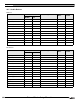
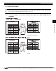
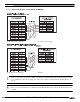
11.1 Connection Table
11.1.1 Compatible PLCs
Series Name System (CPU unit) Link Unit WindO/I-NV2 Settings
Interface Flow Control Host I/F Driver
Series90-30
CPU331
*1
, CPU341,
CPU350, CPU351,
CPU352, CPU360,
CPU363, CPU364,
CPU374
*1. We tested with the PLC of these parts.
IC693CMM311 RS232C
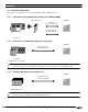
Connection Diagram 1
(refer to P327)
Hardware Series 90
(SNP-X)
RS422/485 4-wire
Connection Diagram 2
(refer to P329)
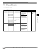
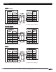
CPU311, CPU313,
CPU323, CPU331
*1
,
CPU341, CPU350,
CPU351, CPU352,
CPU360, CPU363,
CPU364, CPU374
Not required
(connects to CPU
(Power Supply) unit
directly)
RS422/485 4-wire
Connection Diagram 3
(refer to P332)
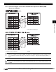
VersaMax Nano Not required
(connects to CPU unit
directly)
RS232C
Connection Diagram 4
(refer to P335)
Micro (14point)
Micro (23, 28
*1
point)
RS232C
Connection Diagram 4
(refer to P335)
RS422/485 4-wire
Connection Diagram 3
(refer to P332)