
User guide

311
9 JTEKT (Toyoda)
2
2
2
2
2
2
2
2
2
2
2
2
2
2
2
Connection to a PLC
External Device Setup Manual
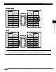
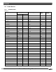
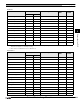
Extended input EX EX 0 - 7FF R/W
Extended output EY EY 0 - 7FF R/W
Extended Internal relay EM EM 0 - 1FFF R/W
Extended keep-relay EK EK 0 - FFF R/W
Extended link relay EL EL 0 - 1FFF R/W
Extended special relay EV EV 0 - FFF R/W
Extended edge detection EP EP 0 - FFF R/W
Extended timer contact ET ET 0 - 7FF R
Extended counter contact EC EC 0 - 7FF R
Extended input GX GX 0 - FFFF R/W
*2
Extended output GY GY 0 - FFFF R/W
*2
Extended Internal relay GM GM 0 - FFFF R/W
*2
*1. Parameter-set program No. in “Link parameter” is an objective of command processing.When the built-in standard link parameters are not set,
Probram1 is an objective of command processing.
*2. These devices are available in the case of a PC3JG mode.
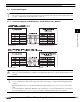
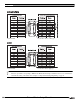
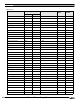
Word Device
Device Name Device Symbol Address Range Read
/Write
Address
Gradual
MICRO/I PLC
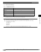
Input WX X 0 - 7F R/W
Output WY Y 0 - 7F R/W
Internal relay WM M 0 - 7F R/W
*1
Keep-relay WK K 0 - 2F R/W
*1
Link relay WL L 0 - 7F R/W
*1
Timer contact WT T 0 - 1F R
*1
Counter contact WC C 0 - 1F R
*1
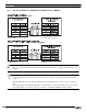
Present value register N N 0 - 1FF R
*1
Data register D D 0 - 2FFF R/W
*1
Link register R R 0 - 7FF R/W
*1
Special register S S 0 - 3FF R/W
*1
File register B B 0 - 1FFF R/W
*1*2
Internal relay P3WM M 0 - 7F R/W
Keep-relay P3WK K 0 - 2F R/W
Link relay P3WL L 0 - 7F R/W
Timer contact P3WT T 0 - 1F R
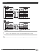
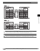
Bit Device
Device Name Device Symbol Address Range Read
/Write
Address
Gradual
MICRO/I PLC