
User guide


301
8 Hitachi
2
2
2
2
2
2
2
2
2
2
2
2
2
2
2
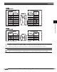
Connection to a PLC
External Device Setup Manual
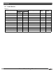
Word Device
Device Name Device Symbol Address Range Read
/Write
Address
Gradual
MICRO/I PLC
Input Relay XW X 0 - 7F0 R/W
Output Relay YW Y 0 - 7F0 R/W
Internal Relay RW R 0 - 7F0 R/W
Global Link GW G 0 - FF0 R/W
System Register SW S 0 - BF0 R
E Word EW EW 400 - FF0 R/W
Event WE E 0 - F0 R/W
Keep Relay KW K 0 - 1F0 R/W
On-Delay Timer (contact) TW T 0 - 1F0 R
One Shot Timer (contact) UW U 0 - 70 R
Up/Down Counter (contact) CW C 0 - 30 R
On-Delay Timer (elapsed value) TC T 0 - 1FF R
On-Delay Timer (setup value) TS T 0 - 1FF R/W
One Shot Timer (elapsed value) UC U 0 - 7F R
One Shot Timer (setup value) US U 0 - 7F R/W
Up/Down Counter (elapsed value) CC C 0 - 3F R
Up/Down Counter (setup value) CS C 0 - 3F R/W
Work Register FW FW 0 - BFF R/W
Data Register
*1
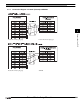
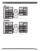
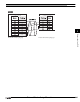
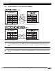
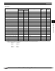
*1. When you use word device as bit device, the bit position reverses the order, as shown in the example.
Example: specified address read address
DW 0-0 DW 0-15
DW 0-1 DW 0-14
: :
DW 0-14 DW 0-1
DW 0-15 DW 0-0
DW DW 0 - FFF R/W