
User guide

287
8 Hitachi
2
2
2
2
2
2
2
2
2
2
2
2
2
2
2
Connection to a PLC
External Device Setup Manual
8Hitachi
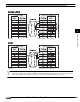
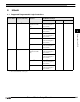
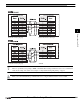
8.1 Supported Programmable Logic Controllers
Series Name System (CPU unit) Link unit WindO/I-NV2 Settings
Interface Flow control Host I/F Driver
S10mini
S10mini
*1
*1. We tested with the PLC of these parts.
Not required
(built into the CPU
unit)
RS422/485 4-wire
Connection Diagram 1
(refer to P290)
Hardware S10mini
LQE160 RS232C
Connection Diagram 2
(refer to P293)
LQE165 RS422/485 4-wire
Connection Diagram 3
(refer to P296)
LQE560 RS232C
Connection Diagram 2
(refer to P293)
LQE565 RS422/485 4-wire
Connection Diagram 3
(refer to P296)
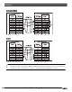
S10V
*1
LQP510
*1
Not required
(built into the CPU
unit)
RS232C
Connection Diagram 2
(refer to P293)
RS422/485 4-wire
Connection Diagram 3
(refer to P296)
LQE560
*1
RS232C
*1
Connection Diagram 2
(refer to P293)
LQE565 RS422/485 4-wire
Connection Diagram 3
(refer to P296)