
User guide

241
6 Keyence
2
2
2
2
2
2
2
2
2
2
2
2
2
2
2
Connection to a PLC
External Device Setup Manual
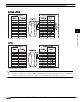
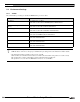
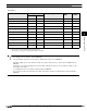
6.2 System Configuration
This is the system configuration for the connection of Keyence PLCs to the MICRO/I.
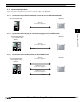
6.2.1 Connection to the CPU unit modular connector for KV-700/1000/3000/5000
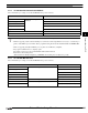
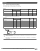
6.2.2 Connection to the D-sub, 9P connector plug type for KV-L20R/KV-L20V
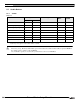
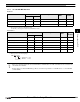
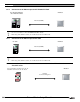
6.2.3 Connection to the terminal block for KV-L20R/KV-L20V
KV-700/1000/3000/5000 MICRO/I
RS232C
Connection Diagram 1
KV-700/1000/3000/5000
+ KV-L20R/KV-L20V
MICRO/I
(PORT1)
RS232C
Connection Diagram 2
KV-700/1000/3000/5000
+ KV-L20R/KV-L20V
RS232C
Connection Diagram 3
MICRO/I
(PORT2)
RS422/485 4-wire
Connection Diagram 4
RS422/485 2-wire
Connection Diagram 5