
User guide

Chapter 2
240
External Device Setup Manual
6 Keyence
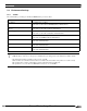
6.1 Connection Table
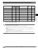
6.1.1 Compatible PLCs
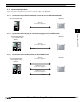
Series Name System (CPU unit) Link unit WindO/I-NV2 Settings
Interface Flow Control Host I/F Driver
KV-700,
1000
*1
,
3000,
5000
*1
KV-700
*1
,
KV-1000
*1
,
KV-3000,
KV-5000
*1
*1. We tested with the PLC of these parts.
Not required
(connects to CPU unit)
RS232C
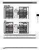
Connection Diagram 1
(refer to P243)
Hardware/
None
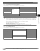
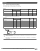
KV-3000/5000
KV-700
*1
,
KV-1000
*1
,
KV-3000,
KV-5000
*1
KV-L20R
*1
,
KV-L20V
RS232C(PORT1)
Connection Diagram 2
(refer to P245)
RS232C(PORT2)
Connection Diagram 3
(refer to P247)
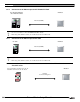
RS422/485 4-wire
Connection Diagram 4
(refer to P249)
RS422/485 2-wire
Connection Diagram 5
(refer to P252)
KV-LE20A,
KV-LE20V
Ethernet - KV (Ethernet)
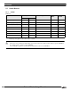
KV-5000
*1
Not required
(connects to Ethernet
port)
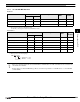
Conventional
KV
KV-10, 16, 20, 40
KV-80
*1
Not required
(connects to CPU unit)
RS232C
Connection Diagram 1
(refer to P243)
None KV/KZ
Visual KV
*2
*2. MICRO/I does not support all device addresses of the Visual KV series.
KV-10
*1
KV-16, 24, 40