
User guide

Chapter 2
238
External Device Setup Manual
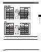
5.5.2 S7- 300/400 with Communication Module
When using CP-341/441, following devices can be read and written.
When using CP-340440, only a data block (DB) can be read and written.
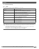
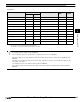
Bit Device
Device Name Device Symbol Address Range Read
/Write
Address
Gradual
MICRO/I PLC
Input (Bit) I I 0 - 1277 R
*1
*1. The 1st figure is written in octal number format,
and the 2nd [or more] figure is written in decimal number format.
Output (Bit) Q Q 0 - 1277 R
*1
Memory (Bit) M M 0 - 2557 R
*1
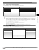
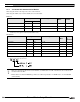
Word Device
Device Name Device Symbol Address Range Read
/Write
Addres
s
Gradual
MICRO/I PLC
Input (Word) IW IW 0 - 126 R
*1
*1. Only an even number can be specified.
Output (Word) QW QW 0 - 126 R
*1
Bit Memory (Word) MW MW 0 - 254 R
*1
Timer cell T T 0 - 127 R Dec
Counter cell C C 0 - 63 R Dec
Data Block DB DB 1000 - 255510 R/W
*1*2
*2. Please specify in the following ranges.
- When a non activated data block is accessed in the PLC, a communication error will occur. Please be sure to activate rele-
vant data blocks in the PLC.
- Endians differ in S7-300, and MICRO/I type. Please use neither bit specification of a WORD device, nor 32-bit WORD
(double WORD).