
User guide

237
5 SIEMENS
2
2
2
2
2
2
2
2
2
2
2
2
2
2
2
Connection to a PLC
External Device Setup Manual
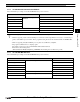
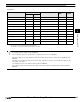
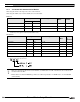
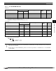
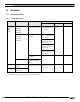
Word Device
Device Name Device Symbol Address Range Read
/Write
Address
Gradual
MICRO/I PLC
Variable memory VW VW 0 - 10238 R/W
*1
*1. Only even number can be specified.
Timer (Current Value) TW T 0 - 255 R/W Dec
Counter (Current Value) CW C 0 - 255 R/W Dec
Process-image-input-register IW IW 0 - 14 R
*1
Process-image-output-register QW QW 0 - 14 R/W
*1
Bit memory MW MW 0 - 30 R/W
*1
Special Memory SMW SMW 0 - 548 R
*1
Analog input AIW AIW 0 - 62 R
*1
Analog output AQW AQW 0 - 62 R/W
*1
Sequential control relay SW SW 0 - 30 R/W
*1
High speed counter HC HC 0 - 51 R
*2
*2. The 1st figure is written with the number of binary number,
and the 2nd [or more] figure is written with the number of decimal.
- The devices (V, I, Q, M, SM, S) which include a period in the address in S7-200 are written without a period in MICRO/I.
For example, V10.1 is written as V101 in MICRO/I.
AC (Accumulator registers), L (Local memory) of PLC Devices can not use in MICRO/I.
- The value of High speed counter which is a double word value is divided into two, and is treated as WORD device in
MICRO/I.
The higher word is written by adding 0 to the lowest digit of the address, the lower word is written by adding 1 to the
lowest digit of the address.
For example, the lower word of HC1 is written as HC11 in MICRO/I.
If you read in a double word value, The lowest digit of the address write 0. For example, HC2 is written as HC20 in
MICRO/I.