
User guide

Chapter 2
220
External Device Setup Manual
5SIEMENS
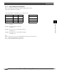
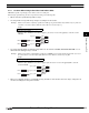
5.1 Connection Table
5.1.1 Compatible PLCs
Series Name System (CPU unit) Link Unit WindO/I-NV2 Settings
Interface Flow Control Host I/F Driver
S7-200 CPU212, CPU214,
CPU215, CPU216
*1
,
CPU221, CPU222,
CPU224, CPU224XP,
CPU226,
CPU226XM
*1
*1. We tested with the PLC of these parts.
Not required
(connects to CPU
unit directly)
RS422/485 2-wire
Connection Diagram 1
(refer to P222)
None S7-200(PPI)
S7-300
CPU 313
*1
, CPU 314,
CPU 315,
CPU 315-2DP
*1
CPU 316, CPU 318
CP-340
*1
CP-341
*1
RS232C
Connection Diagram 2
(refer to P227)
Hardware S7-300 3964(R)
/RK512
RS422/485 4-wire
Connection Diagram 3
(refer to P229)
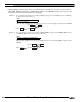
None
CPU 313-2PtP Not required
(connects to CPU
unit directly)
RS422/485 2-wire
Connection Diagram 4
(refer to P231)
None S7-MPI
S7-400 CPU 412, CPU 414,
CPU 416,
CPU 416F-2
*1
,
CPU 417
CP-440,
CP-441
*1
RS232C
Connection Diagram 2
(refer to P227)
Hardware S7-300 3964(R)
/RK512
RS422/485 4-wire
Connection Diagram 3
(refer to P229)
None