
User guide

217
4 Allen-Bradley
2
2
2
2
2
2
2
2
2
2
2
2
2
2
2
Connection to a PLC
External Device Setup Manual
4.7.5 Cautions When Using Indirect Read and Indirect Write
MICRO/I is capable of specifying a device address offset for certain parts.
When using Logix Native Tag, the offset is specified according to the following rules.
• Offsets cannot be specified for tags with no arrays.
• The array number for tags with arrays changes according to the offset value.
• The offset value will change to match the array numbers in the structure if TIMER, COUNTER, CONTROL or user-
defined structure data type array is created.
• When a user-defined structure is created with an array, if members of the structure also have arrays, change the off-
set value according to the array of the member.
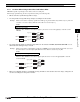
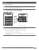
Example: When a device address of [0,0,0] is specified for a INT type tag created with an array element of [2,3,4], if the off-
set value is 1, use data of [0,0,1]. When the offset value is 5, use data of [0,1,1].
Script
[LDR 200] = OFFSET(tag[0,0,0],[LDR 0]);
Operation description
When the value of LDR0 is 1, the value of tag[0,0,1], the device 1 words from tag[0,0,0], is read and stored in
LDR200.
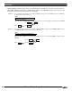
Example: When a device address of [0,0,0].EN is specified for a TIMER type tag created with an array element of [2,3,4], if
the offset value is 1, use data of [0,0,1].EN. When the offset value is 5, use data of [0,1,1].EN.
Script
[LM 200] = OFFSET(tag[0,0,0].EN,[LDR 0]);
Operation description
When the value of LDR0 is 1, the value of tag[0,0,1].EN, the device 1 words from tag[0,0,0].EN, is read and
stored in LDR200.
Read
0000
tag[0,0,1]
0001 LDR0
+1
12341234LDR200
tag[0,1,1]
12341234LDR200
+5
tag[0,0,0]
Read
0005 LDR0
Read
0000
tag[0,0,1].EN
0001 LDR0
+1
11LM200
tag[0,1,1].EN
11234LM200
+5
tag[0,0,0].EN
Read
0005 LDR0