
User guide

Chapter 2
202
External Device Setup Manual
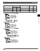
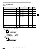
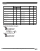
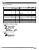
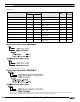
Word Device
Device Name Device Symbol Address Range Read
/Write
Addres
s
Gradual
MICRO/I PLC
Input WI I
0 - 277
*1
*1. Address selection rule is as follows.
R8
Output WO O
0 - 277
*1
R/W 8
Bit WB B
3000 - 99999
*2
*2. Address selection rule is as follows.
R/W 10
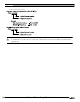
Timer (current value) TA T
3000 - 99999
*2
R10
Counter (current value) CA C
3000 - 99999
*2
R10
Timer (preset value) TP T
3000 - 99999
*2
R/W 10
Counter (preset value) CP C
3000 - 99999
*2
R/W 10
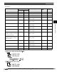
Integer N N
3000 - 99999
*2
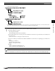
*3
*3. System Area should assigned using a file number between 1 and 9 only. It will not work with file number 10 or above. You must construct an
area in the PLC-5 data table file that corresponds to the System Area Address selected by WindO/I-NV2.
R/W 10
BCD D D
3000 - 99999
*2
R/W 10
ASCII A A
3000 - 99999
*2
R/W 10