
User guide

169
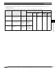
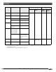
4 Allen-Bradley
2
2
2
2
2
2
2
2
2
2
2
2
2
2
2
Connection to a PLC
External Device Setup Manual
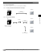
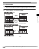
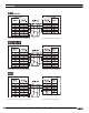
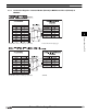
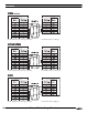
4.3 Connection Diagram
The connector types given in the Connection Diagrams are for the unit and not the cable. For details regarding wiring and
termination resistors, refer to Chapter 1 "3 Important Points Regarding Wiring" on page 19.
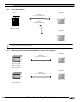
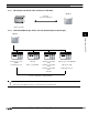
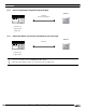
4.3.1 Connection Diagram 1: SLC 500 (RS232C) to MICRO/I
D-sub, 9P connector plug type (unit side) D-sub, 9P connector plug type
D-sub, 9P connector plug type (unit side) Terminal