
User guide


Chapter 2
162
External Device Setup Manual
4 Allen-Bradley
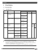
4.1 Connection Table
4.1.1 Compatible PLCs
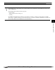
If your existing project is using "SLC500" with Ver.2.30 or earlier, "SLC500 (Half Duplex)" will appear to the Protocol set-
ting with Ver.2.40 or later. SLC 500 (Half Duplex) driver is merged into the MicroLogix1200 (Full Duplex) driver.
WindO/I-NV2 software still provides the SLC 500 (Half Duplex) driver for the existing projects, but it's recommended to
use the MicroLogix1200 (Full Duplex) driver if you create a new project.
Some address format between MicroLogix 1200 (Full Duplex) and SLC 500 (Half Duplex) are slight different.
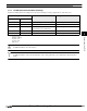
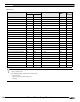
Series Name System (CPU unit) Link unit WindO/I-NV2 Settings
Interface Flow Control Host I/F Driver
PLC-5
All PLC-5
*1
models
that can be connected
to 1770-KF2
1770-KF2
*1
RS232C
Connection Diagram 2
(refer to P171)
Hardware PLC-5
RS422/485 4-wire
Connection Diagram 3
(refer to P173)
All PLC-5
*1
models
Not required
(connects to CPU unit)
RS232C
Connection Diagram2
(refer to P171)
RS422/485 4-wire
Connection Diagram 4
(refer to P176)
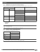
SLC 500
SLC5/03
*1
,
SLC5/04,
SLC5/05
Not required
(connects to CPU unit)
RS232C
Connection Diagram 1
(refer to P169)
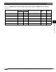
MicroL
ogix/
SLC500
Full
Duplex)
SLC5
00
(Half
Duple
x)
Micro-Logix MicroLogix1000,
MicroLogix1200
*1
*1. We tested with the PLC of these parts.
Not required
(connects to CPU unit)
RS232C
Connection Diagram 5
(refer to P179)
MicroLogix1100
*1
Not required
(connects to CPU unit)
RS232C
Connection Diagram 8
(refer to P185)
-
MicroLogix1500
*1
Not required
(connects to Mini Din
connector on CPU unit)
RS232C
Connection Diagram 5
(refer to P179)
Not required
(connects to D-sub
connector on CPU unit)
RS232C
Connection Diagram 6
(refer to P181)