
User guide


Chapter 2
106
External Device Setup Manual
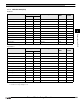
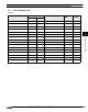
Word Device
Device Name Device Symbol Address Range Read
/Write
Address
Gradual
MICRO/I PLC
Input Relay WX X 0 - 1F0 R
*1
*2
*1. Set this device using hexadecimal.
*2. Set this device using a multiplier of 16.
Output Relay WY Y 0 - 1F0 R/W
*1
*2
Internal Relay WM M 0 - 2032 R/W
*2
Link Relay WB B 0 - 3F0 R/W
*1
*2
Latch Relay WL L 0 - 2032 R/W
*2
Timer (current value) TN T 0 - 255 R
Counter (current value) CN C 0 - 255 R
Data Register D D 0 - 1023 R/W
Link Register W W 0 - 3FF R/W
*1
Annunciator WF F 0 - 240 R/W
*2
Special Internal Relay WSM SM 9000 - 9240 R
*3
*3. This can only be used when the Link Unit is being used.
Special Register SD SD 9000 - 9255 R
File Register R R 0 - 8191 R/W
- File Register is not available, if Memory Cassettes is used.
- File Register is tested only MELSEC-A1S/A1SH/A1SJH/A2SH/A2C.
Don’t use expect those CPU Unit.
- In case of using File Register, must reset to MICRO/I if PLC parameter is changed.