
Manual

3 Pie Chart
11-50 WindO/I-NV2 User’s Manual
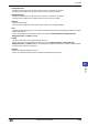
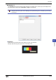
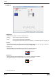
● View Ta b
■ Browse
Select the type of graphic to be used to represent the part from the list of graphics. Click this button to display the
View Browser.
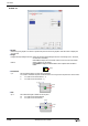
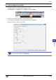
■ Flange
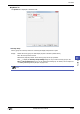
■ Coordinates
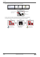
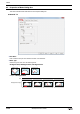
■ Size
Foreground Color, Background Color: Selects the foreground and background colors of the flange (color: 256 colors,
monochrome: 16 shades).
Click Color to display the Color Palette. Select a color from the Color Palette.
Pattern: Selects a pattern for the flange.
Click Pattern to display the Pattern Palette. Select a pattern from the Pattern
Palette.
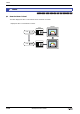
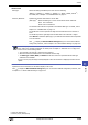
Flange
X, Y: Sets the display position of parts using coordinates.
The X and Y coordinates of parts are defined relative to an origin at the top-left corner of the screen.
X: 0 to (base screen horizontal size - 1)
Y: 0 to (base screen vertical size - 1)
(0, 0)
X
Y
Screen
Parts
W, H: Sets width and height to define the size of parts.
W: 5 to (base screen horizontal size)
H: 5 to (base screen vertical size)
Width
Height
Screen
Parts