
Manual

WindO/I-NV2 User’s Manual 10-83
5 Message Display
10
Data Displays
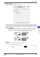
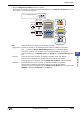
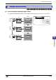
•When the Change Color by Device check box is selected
The colors that correspond to the values stored in the device addresses for Change Color by Device and the this
device address + 1 are alternately displayed.
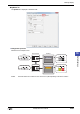
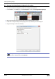
Enable: Selects this check box to make text color and plate color flash.
Trigger Device: Specifies the bit device or word device that will be used as a condition to trigger flash.
Click to display the Device Address Settings dialog box. For the device address
configuration procedure, refer to Chapter 2 “5.1 Device Address Settings” on page 2-67.
Flash intervals are set in the Flashing Cycle on the System tab in the Project Settings dialog
box.
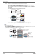
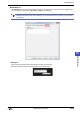
Text Color: Selects the color (color: 256 colors, monochrome: 16 shades) of text when flashing.
Click this button to display the Color Palette. Select a color from the Color Palette.
This option can only be configured when the Change Color by Device check box is cleared.
Plate Color: Selects the plate color (color: 256 colors, monochrome: 16 shades) when flashing.
Click this button to display the Color Palette. Select a color from the Color Palette.
This option can only be configured when the Change Color by Device check box is cleared and
Standard is selected for Image Type on the View tab.
HG SERIES
HG SERIES
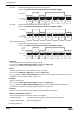
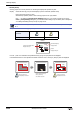
Flashing
MICRO/I
External device
HG SERIES
HG SERIES
Lower byteUpper byte
D0
0x14
0x16
Lower byteUpper byte
D1
0xF7
0x23
Text colorPlate color
Text color
when flashing
Plate color
when flashing
0
1
D0=
Lower byteUpper byte
0x140x16
D1=
0xF70x23
Trigger device
Device for Change Color by Device
+1