
Manual

3 Project Settings Dialog Box
4-32 WindO/I-NV2 User’s Manual
● System Area
Overview
The area of predetermined devices to control the screen and communicate error information and time information
between the MICRO/I and the host is called the System Area.
The System Area on the MICRO/I is as follows.
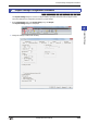
To use System Area 1 and 2, select the Use System Area check box on the Project Settings dialog box. To use
System Area 3 and 4, select the Use System Area 3, 4 check box.
Specify the word device to use as the System Area in Device to allocate the System Area starting at the configured
device address.
Click to display the Device Address Settings dialog box. For the device address configuration procedure, refer
to Chapter 2 “5.1 Device Address Settings” on page 2-67.
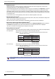
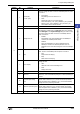
Example: When Device is configured as LDR 100
System Area 1
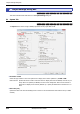
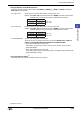
This area configures the MICRO/I display, beep, and clearing bits.
System Area Number of word addresses User Access
System Area 1 2 Read and write
System Area 2 2 Write
System Area 3 4 Read
System Area 4 4 Write
LDR 100
LDR 101
LDR 102
LDR 103
LDR 104
LDR 105
LDR 106
LDR 107
LDR 108
LDR 109
LDR 110
LDR 111
System Area 1
(Start address)
+1
+2
+3
+4
+5
+6
+7
+8
+9
+10
+11
System Area 2
System Area 3
System Area 4
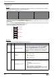
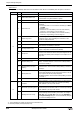
Address Bit Function Description
+0 0 to 15 Display screen number
This bit stores the number of the screen being displayed. Write a
value to this bit to change the screen to that number. Immediately
after the power is turned on, the value configured by Default
Screen in the Project Settings dialog box is stored here.
If the screen number does not exist in the project data, an error
message (No screen data) is displayed. However, when 0 is written
to this bit, the screen is not switched and no error message is
displayed.
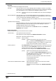
+1
0 Backlight
This bit stores the illumination state of the backlight. Write a value to
this bit to change the state.
0: Off
Turns the backlight off.
1: On
Turns the backlight on.
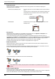
1 Flash display (1 sec. cycle)
This bit stores the screen flash state (1 sec. cycle). Write a value to
this bit to change the state. This bit is 0 immediately after the power
is turned on.
0: Do not flash
Stop flashing the screen and turn it on.
1: Flash
Flashes the screen in one second intervals.
When flash display (1 sec. cycle) (address+1, bit 1) and flash
display (0.5 sec. cycle) (address+1, bit 2) are both 1, the
screen flashes at one second intervals.