
Manual

5 User Communication
3-42 WindO/I-NV2 User’s Manual
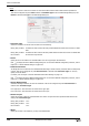
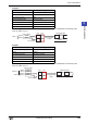
Example 3
When the trigger condition is satisfied, the value of device is read, and data is converted to ASCII and transmitted in
the following order.
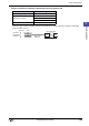
Example 4
When the trigger condition is satisfied, the value of device is read, and data is converted to ASCII and transmitted in
the following order.
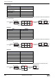
Example 5
When the trigger condition is satisfied, the value of device is read and data is transmitted in the following order.
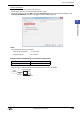
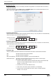
Item Setting
Conversion Type Binary (HEX) to ASCII
Device LDR100
Use Reference Device OFF
Number of bytes 2
Words 2
Variable OFF
Item Setting
Conversion Type Binary (DEC) to ASCII
Device LDR100
Use Reference Device OFF
Number of bytes 2
Words 2
Variable OFF
Item Setting
Conversion Type No Conversion
Device LDR100
Use Reference Device OFF
Storage Method of data from Upper byte
Number of bytes 2
Words 2
Variable ON, NULL
1234hLDR100:
5678hLDR101:
Binary (HEX) to ASCII
1
(31h)
Value of Device
4
(34h)
5
(35h)
2
(32h)
6
(36h)
3
(33h)
7
(37h)
8
(38h)
2 bytes
Transmission data
3
(33h)
4
(34h)
7
(37h)
8
(38h)
Order of transmission
Words: 2
1234LDR100:
5678LDR101:
1
(31h)
4
(34h)
5
(35h)
2
(32h)
6
(36h)
3
(33h)
7
(37h)
8
(38h)
3
(33h)
4
(34h)
7
(37h)
8
(38h)
Binary (DEC) to ASCII
Value of Device
Transmission data
Order of transmission
2 bytes
Words: 2
1234hLDR100:
0056hLDR101:
No conversion
12h
Upper Lower
Value of Device
34h
56h00h
from Upper byte
2 bytes
Transmission data
12h 34h
Order of transmission
Words: 2