
Manual

WindO/I-NV2 User’s Manual 34-83
6 HG2S
34
MICRO/I Specifications
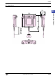
6.9 Wiring
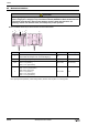
● Connector classification
D-sub 37P connector (plug): DC-37-PF-N (JAE)
D-sub 37P connector (hood): DC-C8-J13-F1-1 (JAE)
●
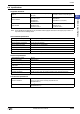
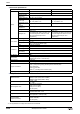
Connector wiring table
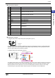
CAUTION
• Turn off the power supply before wiring.
• Make the wiring as short as possible and run all wires as far away as possible from high-voltage
and large-current cables. Follow all the procedures and precautions when wiring the HG2S.
• Separate the HG2S power supply wiring from the power lines of I/O devices and motor equipment.
• Ground the functional earth terminal to make sure of correct operation.
20
19
1
37
Connector Male Side
No. Name Function Cable Color
1 FG Frame ground Cable shield (In, Out)
2 NC No connection
3
A1 A1 Emergency stop SW or Stop SW
Out Single 7: Blue (Thick)
4 Out Single 8: Gray (Thick)
5
A2 A2 Emergency stop SW or Stop SW
Out Single 9: Pink (Thick)
6
Out Single10:Orange (Thick)
7 DC24+ Power supply input
Out Single 2: White (Thick)
8 DC24+ Power supply input Out Single 3: Red (Thick)
9 24V DC- Power supply ground Out Single 1: Black (Thick)
10 24V DC- Power supply ground
Out Single 4: Green (Thick)
11 I/O + External I/O power
Out Single 5: Yellow (Thick)
12 I/O - External I/O power
Out Single 6: Brown (Thick)
13 Y0 External output 0 (LY0) Out Pair 1: Blue (Thin)
14 Y1 External output 1 (LY1) Out Pair 2: Yellow (Thin)
15 O RUN Run output (LY2) Out Pair 2: Brown (Thin)
16 X0 External input 0 (LX0) Out Pair 3: Green (Thin)
17 X1 External input 1 (LX1) Out Pair 3: Brown (Thin)
18 X2 External input 2 (LX2) Out Pair 4: Red (Thin)
19 X3 External input 3 (LX3) Out Pair 4: Brown (Thin)
20
B1 B1 Enabling SW
Out Pair 7: Yellow (Thin)
21 Out Pair 7: Black (Thin)
22
B2 B2 Enabling SW
Out Pair 8: Green (Thin)
23 Out Pair 8: Black (Thin)
24
D1 NO1
(C1 NO2)
D1 Contact 1 (C1 Contact 2) Out Pair 5: Purple (Thin)
25
D2 NO1
(C2 NO2)
D2 Contact 1 (C2 Contact 2) Out Pair 5: Brown (Thin)
26
C1 NO1
(D1 NO2)
C1 Contact 1 (D1 Contact 2) Out Pair 6: Blue (Thin)