
Manual

WindO/I-NV2 User’s Manual 34-77
6 HG2S
34
MICRO/I Specifications
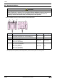
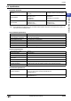
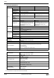
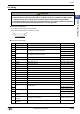
● Connector Pin Functions
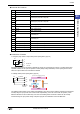
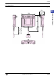
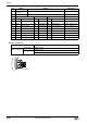
● Construction of Contact
1. Emergency stop switch or Stop switch (Direct opening action) (A1, A2)
Emergency stop switch or stop switch is available to connect to an emergency stop circuit. It remains locked when
operated. Contacts do not open the operator is locked (safety locking mechanism). Direct opening circuit function
ensures to open contacts even if contacts are welded.
2. Enabling switch (Direct opening action) (B1, B2)
The enabling switch consists of two contacts (OFF-ON-OFF). They can be wired so that the contacts can be monitored
mutually using two input points. Each contact works independently, so the end of the switch at operation, a time
difference between the two contacts may occur. Wire the enabling switch so that the contacts can be mutually
monitored using two input points. Design a sequence program in consideration of the time difference.
No. Name Function
1 FG Frame ground
2NC
3
A1 A1 Emergency stop SW or Stop SW
4
5
A2 A2 Emergency stop SW or Stop SW
6
7 24V DC+ Power supply input
8 24V DC+ Power supply input
9 24V DC- Power supply ground
10 24V DC- Power supply ground
20
B1 B1 Enabling Sw
21
22
B2 B2 Enabling Sw
23
24 D1 NO1 (C1 NO2) D1 Contact 1 (C1 Contact 2)
25 D2 NO1 (C2 NO2) D2 Contact 1 (C2 Contact 2)
26 C1 NO1 (D1 NO2) C1 Contact 1 (D1 Contact 2)
27 C2 NO1 (D2 NO2) C2 Contact 1 (D2 Contact 2)
28 SW COM C1, C2, D1, D2 common
4
6
3
5
A1
A2
D-sub 37P
Pin No.
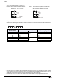
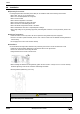
[Action of the enabling switch]
3 positon
(OFF-ON-OFF)
B1
B2
21
23
20
22
D-sub 37P
Pin No.
OFF
ON
OFF
Push
lightly
Release
Push
further
Release