
Manual

WindO/I-NV2 User’s Manual 34-75
6 HG2S
34
MICRO/I Specifications
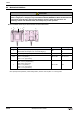
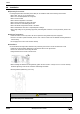
● Serial Interface2
• Connect pin 6 (EN) and pin 2 (ER) unless performing maintenance communications for downloading project data.
Use Printer connection cable (FC2A-KP1C) when the HG2S be connected with the printer. (Refer to the printer
Instruction Manual for details.)
●
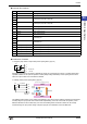
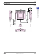
External Input/Output Interface
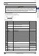
• Connector Pin Functions
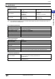
Interface Specification RS232C
Connector Mini DIN 8P
No. Name I/O Function
1 RS OUT Request to Send
2 ER OUT Data terminal ready
3SD OUT Send Data
4 RD IN Receive Data
5 DR IN Data set ready
6 EN IN Use set ready
7 SG - Signal Ground
8 NC - No connection
1
2
3
4
5
6
7
8
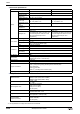
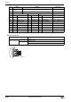
Input
Input Points 4
Rated Input Voltage 12 to 24 V DC (Allowable Voltage Range: 10 to 28V)
Isolation Photocoupler isolated
Input Impedance / Input Current
Approx. 3.9k ohm / Approx. 6mA
Input voltage: 24V DC
Input Voltage Level
ON voltage: 8V or more
OFF voltage: 4V or less
Output
Output Points 3 (Included Run output)
Rated Load Voltage 12 to 24 V DC (Allowable Voltage Range: 10 to 28V)
Isolation Photocoupler isolated
Output Type / ON Voltage NPN open collector / 1.6V maximum
Maximum Load Current 50 mA per output point
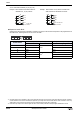
No. Name Function
11 I/O+ External I/O power +
12 I/O- External I/O power -
13 Y0 External output (LY0)
14 Y1 External output (LY1)
15 O RUN Run output (LY2)
16 X0 External input0 (LX0)
17
X1 External input1 (LX1)
18
X2 External input2 (LX2)
19
X3 External input3 (LX3)