
Manual

6 HG2S
34-74 WindO/I-NV2 User’s Manual
6.4
External Interfaces
● Serial Interface1
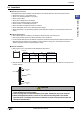
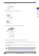
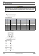
• Connector Pin Layout
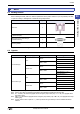
• Connector Pin Functions
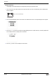
• Communication switch settings
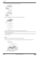
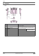
• RS232C (Set at factory)
• RS485C (Set at factory)
• RS422 (Change setting)
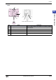
CAUTION
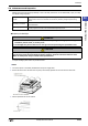
When using the maintenance port (Serial interface2) or setting up communication switches, remove
the maintenance port cover. After setting up, screw down the cover using four M3 screws. To ensure
that the water-resistance characteristics are maintained, tighten the screws to a torque of 0.6 to
0.7N•m.
RS232C RS485 RS422
No. Name Function Name Function Name Function
29 SG Signal Ground SG Signal Ground SG Signal Ground
30 SD1 Send Data 1 SDA Send Data A SD+ Send Data (+)
31 --- Reserved SDB Send Data B SD- Send Data (-)
32 RD1 Receive Data 1 RDA Receive Data A RD+ Receive Data (+)
33 --- Reserved RDB Receive Data B RD- Receive Data (-)
34 ER Data terminal ready --- --- RS+ Request to Send (+)
35 NC --- --- --- RS- Request to Send (-)
36 DR Data set ready --- --- CS+ Clear to Send (+)
37 NC --- --- --- CS- Clear to Send (-)
19
1
20
37
Inside of Maintenance Port Cover
(Serial Interface2)
maintenance port
SW2: terminator
SW1: RS485/RS422
SW1
SW2
Down
Down
SW1
SW2
Up (RS-485)
Up (OFF)
SW1
SW2
Down (RS422) Down (ON)