
Manual

WindO/I-NV2 User’s Manual 34-73
6 HG2S
34
MICRO/I Specifications
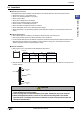
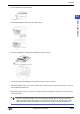
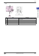
■ Rear
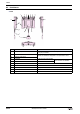
No. Name Description
11 Enabling switch
When an enabling switch is not specified, only the button is installed
without contacts.
12 Mounting Bracket screw holes M3 x 6 tapped holes
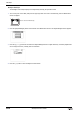
13 Maintenance port cover
14 Maintenance port Mini DIN8P connector (Serial interface2)
15 Communication switch For setting the property of serial intarface1
12
11
13
14
15
Inside of Maintenance Port Cover