
Manual

6 HG2S
34-72 WindO/I-NV2 User’s Manual
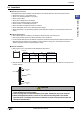
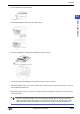
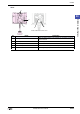
6.3 Part Names
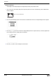
■ Front
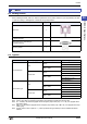
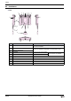
No. Name Description
1 Emergency stop switch or Stop switch
When an emergency stop switch or a stop switch is not specified, a
dummy cap is installed.
2 Push-button switch
Switches are installed as designated on the specification sheet.
3 Expansion switch block
4 CC SWITCH 6 x two columns (right and left)
Without CC SWITCH, 12x16
touch switches are available.
5 Touch switch 12 x 10 switches
6 Cable gland
7 Cable 3m or 5m or 10m
8 D-sub 37-pin connector Plug type
9Hand strap
10 Strap hole
2
5
1
2
2
6
1
4
7
8
10
10
10
10
9
3
3