
Manual

WindO/I-NV2 User’s Manual 34-65
5 HG3F/4F
34
MICRO/I Specifications
5.7
Installation
● Operating Environment
For designed performance and safety of the HG3/4F, do not install the HG3/4F in the following environments:
• Where dust, briny air, or iron particles exist.
• Where oil or chemical splashes for a long time.
• Where oil mist is filled.
• Where direct sunlight falls on the HG3/4F.
• Where strong ultraviolet rays fall on the HG3/4F.
• Where corrosive or combustible gasses exist.
• Where the HG3/4F is subjected to shocks or vibrations.
• Where condensation occurs due to rapid temperature change.
• Where high-voltage or arc-generating equipment (electromagnetic contactors or circuit protectors) exists in the
vicinity.
●
Ambient Temperature
• Allow sufficient space for ventilation, and install the equipment away from heat sources.
• Allow at least 100mm between the HG3/4F and walls or other equipment.
• Do not install the HG3/4F where the ambient temperature exceeds the rated operating ambient temperature range.
When mounting the HG3/4F in such locations, provide a forced air-cooling fan or air-conditioner to keep the
ambient temperature within the rated temperature range.
●
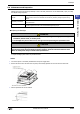
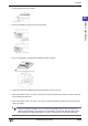
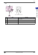
HG3/4F Installation
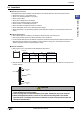
• Make a panel cut-out on the panel with the dimensions shown below.
• Place the HG3/4F in a panel cut-out and fasten with the attached mounting clips at four places to a torque of 0.4 to
0.6 N•m uniformly.
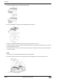
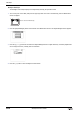
CAUTION
• Do not tighten excessively, otherwise the HG3/4F may warp and cause wrinkle on the display, or
impair the waterproof characteristics.
• If the mounting clips are tightened obliquely to the panel, the HG3/4F may fall off the panel.
• When installing the HG3/4F into a panel cut-out, make sure that the gasket is not twisted.
Especially when re-installing, take special care because any twists in the gasket will impair the
waterproof characteristics.
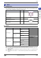
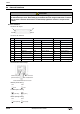
B
A
Unit: mm
Type No. A B Panel Cut-out
HG3F 228.0
+0.5
0
302.0
+0.5
0
2.0 to 5.0
HG4F 258.0
+1.0
0
332.0
+1.0
0
2.0 to 5.0
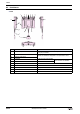
HG3/4F
Mounting
Clip
Mounting
Clip
Panel