
Manual


WindO/I-NV2 User’s Manual 3-3
2 O/I Link Communication
3
Communication
2.1 Overview
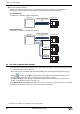
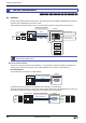
O/I Link Communication is a protocol for communication between Master and Slave, where a MICRO/I connected to
the external device is configured as a Master and multiple MICRO/I (Slaves) communicate with the external device via
the Master.
The Master MICRO/I unit communicates with the external device by means of PLC Link Communication. The Master
MICRO/I is called an O/I Link Master and a slave MICRO/I connected to the O/I Link Master is called an O/I Link
Slave. A maximum of 15 O/I Link Slaves can be connected to an O/I Link Master.
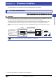
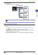
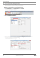
2.2 O/I Link Communication Settings
These settings are configured under the O/I Link tab on the Project Settings dialog box. The Project Settings dialog
box can also be accessed using the following methods.
•Click Project on the Configuration tab.
•Double click Project Settings in the Project window.
The O/I Link Communication Settings can only be configured when O/I Link Master or O/I Link Slave is selected
in Protocol under Interface Settings on the Communication Interface tab. For details, refer to Chapter 4 “3.6
O/I Link Tab” on page 4-50.
2 O/I Link Communication
HG3G
HG2G-5FHG2G-5SHG2G-S
HG4G HG1F HG2F HG2S HG3F HG4F
Read Write
5678
MICRO/I
O/I Link Slave
(Slave 1)
MICRO/I
O/I Link Slave
(Slave 2)
MICRO/I
O/I Link Slave
(Slave 15)
MICRO/I
O/I Link Master
External device
0
1
Read
Write
D1:
M1:
5678
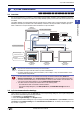
O/I Link Communication
PLC Link Communication
Numerical Display
Reference Device: D1
Bit Button
Destination Device: M1
Read Write Read Write
• The HG2G-S/-5S/-5F, the HG3G/4G, and the HG1F/2F/2S/3F/4F have different O/I Link Communication, therefore
they can not be connected on the same O/I Link Communication.
• The HG2S can only be used as a slave in O/I Link Communication.
• For details regarding the O/I Link Communication, refer to Chapter 3 "O/I Link Communication" in the
"External Device Setup Manual".
• O/I Link Communication is not available when selecting the HG2G-5S USB interface (Serial 2 in
Interface Configuration under Communication Interface tab on the Project Settings dialog box).
• The HG1F cannot simultaneously use Serial Interface 2 and the O/I Link Interface. The interface to use
is set in the Project Settings dialog box on the Communication Interface tab.
• The HG1F cannot use the O/I Link Interface when in the following states.
- The maintenance cable is connected to Serial Interface 2.
-
In the Project Settings dialog box, on the
Host I/F Driver
tab, the
Enable Pass-Through
check box is
selected.