B-1119 (13) Operator Interface User’s Manual
SAFETY PRECAUTIONS Confirm that the delivered product is what you have ordered. Read this manual to make sure of correct operation. SAFETY PRECAUTIONS • Be certain to read this manual carefully before performing installation, wiring, or maintenance work, or operating the HG2G-S/-5S/-5F, HG3G/4G, HG1F/2F/2S/3F/4F. • The HG2G-S/-5S/-5F, HG3G/4G, HG1F/2F/2S/3F/4F has been manufactured with careful regard to quality.
SAFETY PRECAUTIONS • Prevent the HG2G-S/-5S/-5F, HG3G/4G, HG1F/2F/2S/3F/4F from falling while moving or transporting, otherwise damage or malfunction of the HG2G-S/-5S/-5F, HG3G/4G, HG1F/2F/2S/3F/4F will result. • Use the product within the environmental limits given in the catalog and manual. Use of the product in hightemperature or high-humidity environments, or in locations where it is exposed to condensation, corrosive gas or large shock loads can create the risk of electrocution and fire.
Revision history Revision history February 2009: First Edition April 2009: Second Edition August 2009: Third Edition November 2009: Fourth Edition July 2010: Fifth Edition September 2010: Sixth Edition January 2011: Seventh Edition June 2011: Eighth Edition December 2011: Ninth Edition February 2012: Tenth Edition April 2012: Eleventh Edition June 2012: Twelfth Edition June 2013: Thirteenth Edition December 2013: Fourteenth Edition Caution • The contents of this manual and the W
Preface Preface This manual describes MICRO/I operator interfaces (HG2G-S/-5S/-5F, HG3G/4G and HG1F/2F/2S/3F/4F) and WindO/I-NV2 general configuration software. The information includes drawing tools, setup procedures, and how to configure all MICRO/I operator interfaces. This manual explains the operation and handling of the MICRO/I HG2G-S/-5S/-5F, HG3G/4G, HG1F/2F/2S/3F/4F.
Symbols Used in this Manual Symbols Used in this Manual This manual uses the following symbols to facilitate explanation. Symbols …… Useful information relating to a function …… Information that requires special attention. Failure to operate the product in accordance with the information provided can lead to serious injury or damage. …… Indicates the chapter/page of related reference information. OK …… Screen buttons are indicated by bold text or by using the actual graphic icon.
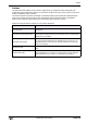
Abbreviations, Generic Terms, and Terminology Used in this Manual Abbreviations, Generic Terms, and Terminology Used in this Manual Item Description HG2G-S The name is short for MICRO/I HG2G-S*2**F-*. HG2G-5S The name is short for MICRO/I HG2G-5ST22*F-*. HG2G-5F The name is short for MICRO/I HG2G-5FT22TF-*. HG3G The name is short for MICRO/I HG3G-*JT22*F-*. HG4G The name is short for MICRO/I HG4G-CJT22*F-B. HG1F The name is short for MICRO/I HG1F-SB22*F-*.
Abbreviations, Generic Terms, and Terminology Used in this Manual Item Description Windows Font Text fonts that can be displayed on the Windows OS on which the WindO/I-NV2 is running. Stroke Font A glyph's outline is defined by the vertices of individual strokes and stroke's profile. Scalable fonts scale easily without jagged edges. Under font settings, “Stroke” is a stroke-based font. Maintenance Communication Communications between the WindO/I-NV2 and MICRO/I using a dedicated protocol.
Contents Contents SAFETY PRECAUTIONS ................................................................................ Preface-1 Revision history ........................................................................................... Preface-3 Caution ....................................................................................................... Preface-3 Trademarks ................................................................................................. Preface-3 Preface ...............
Contents 2 O/I Link Communication.........................................................................................3-3 2.1 2.2 3 DM Link Communication.........................................................................................3-4 3.1 3.2 4 1 Creating and Manipulating WindO/I-NV2 Project Data ..............................................4-1 Creating New Project Data .............................................................................. 4-1 Opening Project Data ............
Contents 4 Project Restrictions ............................................................................................. 4-66 4.1 4.2 Chapter 5 1 Screen Screen Overview................................................................................................... 5-1 1.1 1.2 2 1 2 What You Can Do with Library Screens ........................................................... 5-31 Creating a Library Screen...............................................................................
Contents Chapter 7 1 Drawings Shapes .................................................................................................................7-1 1.1 1.2 1.3 1.4 1.5 1.6 1.7 1.8 1.9 2 Picture ................................................................................................................7-24 2.1 2.2 3 1 Bit Button .............................................................................................................8-1 How the Multi-Button is Used ......................
Contents 8 Selector Switch ..................................................................................................8-130 8.1 8.2 8.3 9 Potentiometer....................................................................................................8-146 9.1 9.2 9.3 Chapter 9 1 Pilot Lamps .......................................................................................................... 9-1 1 Numerical Input............................................................................
Contents 7 Alarm List Display ............................................................................................ 10-102 7.1 7.2 7.3 8 Alarm Log Display............................................................................................ 10-118 8.1 8.2 8.3 9 1 Bar Chart ............................................................................................................11-1 1 Bit Write Command....................................................................................
Contents 4.3 5 Script Command ................................................................................................12-32 5.1 5.2 5.3 6 1 Overview............................................................................................................ 13-1 4.3 4.4 1 Overview............................................................................................................ 14-1 Configuring the Sampling Condition and Devices for Sampling Data ..................
Contents Chapter 15 1 Operation Log Function Overview ............................................................................................................15-1 1.1 1.2 1.3 1.4 1.5 2 Operation Log Function Configuration Procedure....................................................15-8 2.1 3 1 Overview ............................................................................................................16-1 1 Overview ......................................................................
Contents 3.2 4 Creating and Deleting Data for Recipes................................................................18-14 4.1 4.2 4.3 4.4 Chapter 19 1 Overview............................................................................................................ 19-1 1 About the Script Function .................................................................................... 20-1 Format List .................................................................................................
Contents Chapter 21 1 Sound Function Function and Settings ..........................................................................................21-1 1.1 1.2 2 Sound Function Configuration Procedure ...............................................................21-2 2.1 3 Chapter 22 1 Multimedia Function Function and Settings ..........................................................................................22-1 Chapter 23 1 User Accounts and the Security Function Overview ..............
Contents 3 Uploading..........................................................................................................24-22 3.1 3.2 4 Clear.................................................................................................................24-26 4.1 4.2 5 1 Monitoring with WindO/I-NV2 .............................................................................. 25-1 1 Overview Pass-Through .......................................................................................
Contents 2.3 2.4 2.5 2.6 2.7 2.8 2.9 3 Downloader ...................................................................................................... 27-34 3.1 3.2 Chapter 28 1 Project Transfer Function......................................................................................28-1 1 Overview ............................................................................................................29-1 1 Setting Procedures for Cyclic Script.............................................
Contents 1.6 1.7 1.8 2 USB Flash Drives................................................................................................30-25 2.1 2.2 2.3 2.4 2.5 2.6 2.7 2.8 2.9 Chapter 31 1 Functions and Connections .................................................................................. 31-1 1 2 Chapter 33 1 Overview............................................................................................................ 32-1 Internal MICRO/I Devices ....................................
Contents 1.3 1.4 1.5 1.6 1.7 1.8 1.9 2 HG2G-5F, HG3G/4G ........................................................................................... 34-16 2.1 2.2 2.3 2.4 2.5 2.6 2.7 2.8 2.9 2.10 3 Packing content........................................................................................... 34-58 Type No...................................................................................................... 34-58 Part Names ......................................................................
Contents 6.6 6.7 6.8 6.9 6.10 7 Options .............................................................................................................34-86 7.1 7.2 7.3 7.4 7.5 Chapter 35 1 HG1F ......................................................................................................... 34-86 HG2F/3F/4F ................................................................................................ 34-87 HG2S ...................................................................................
Contents Preface -23 WindO/I-NV2 User’s Manual
System Composition Chapter 1 1 System Composition 1 MICRO/I External Device WindO/I-NV2 130 Download Periodically reads values of device Writes changed values of device ● MICRO/I The MICRO/I is equipped with a high-brightness, color LCD with fast screen drawing speed, quick-response touch switches, and high-speed communications to provide a comfortable man-machine interface.
1 System Composition 1.2 System Composition for Creating Screens It is necessary to create and download a project to the MICRO/I for operating it. Use the WindO/I-NV2 to create a project. The project you have created can be downloaded to the MICRO/I by directly connecting it to the computer, or the project data can be downloaded to external memory, and then it can be copied from external memory to the HG2G-5F, HG3G/4G, HG2F/3F/4F equipped with the memory card interface or the USB interface.
2 About the WindO/I-NV2 2 About the WindO/I-NV2 1 Using WindO/I-NV2, you create a project and then download it to the MICRO/I, to build the interface necessary for operation. Download Upload WindO/I-NV2 MICRO/I External memory SD memory card CF card Download Upload Download USB flash drive WindO/I-NV2 User’s Manual Upload 1-3 System Composition WindO/I-NV2 is software that is exclusively designed for operation with the MICRO/I, for specifying settings and creating screens.
3 Operating Modes 3 Operating Modes The MICRO/I includes multiple modes, so you switch between modes as and when necessary. These modes are called operating modes. The functions and the operations and conditions for switching are as follows. Mode Functions Conditions required for switching to the mode This is the mode at the time of executing project data. The created screen is displayed. • Turn ON the power to the MICRO/I. • Press [Run] on the Top Page of system mode or on the System Menu.
4 Flow from Screen Creation and to Run Operation 4 Flow from Screen Creation and to Run Operation 1 1 Launch the WindO/I-NV2 ( refer to Chapter 2 “2.1 Starting WindO/I-NV2” on page 2-39) 2 Creating a Project and Screen Creating a new project ( refer to Chapter 4 “1.1 Creating New Project Data” on page 4-1) System Composition The following flowchart describes the sequence of step from the screen creation for the MICRO/I to the Run operation. • Creating new screens ( refer to Chapter 5 “2.
4 Flow from Screen Creation and to Run Operation 1 Launch WindO/I-NV2 Launch WindO/I-NV2. 2 Creating a Project and Screen Create a project and performing various settings. Create display screens. 3 Downloading the project Connect the computer to the MICRO/I using a USB cable, Ethernet cable or Serial cable and download the created project data to the internal memory of the MICRO/I. 4 Debug Using the monitor function, you can correct created project data while confirming actual actions.
Chapter 2 WindO/I-NV2 Features & Basic Operations This chapter describes the minimum system requirements for WindO/I-NV2, how to start and exit it, and the configuration of its screens and menus. 1 2 WindO/I-NV2 Specifications The table below shows the minimum system requirements for WindO/I-NV2. Item Description OS Windows 7/8 (64-bit and 32-bit versions), Windows Vista (32-bit version), Microsoft Windows XP (32-bit version, Service Pack 3 or later must be installed) CPU 1.
1 WindO/I-NV2 Specifications 1.2 Available Data ● Data types Data type is the format of the data related to the minimum and maximum values of data that can be processed by a part and handling of negative and real numbers. Data types and data ranges that can be used on the MICRO/I and WindO/I-NV2 are listed below.
1 WindO/I-NV2 Specifications Data type Data handling Data is handled as a 32-bit floating-point real number. The number of significant digits is 6 digits. The floating-point type data format conforms to the IEEE (The Institute of Electrical and Electronics Engineers) standard for the single precision storage format as explained next.
1 WindO/I-NV2 Specifications Data type Storing 1234 (hex) in LDR10 bit 15 Storing F765 (hex) in LDR10 bit 15 bit 0 LDR10 0001001000110100 BCD4 + Data type bit 0 LDR10 1111011101100101 234 (Hex) − 765 (Hex) The sign is 1 (hex), so the binary-coded decimal value of the positive number 234 (hex), handled as 1234 (dec). The sign is F (hex), so the binary-coded decimal value of the negative number 765 (hex), handled as -765 (dec).
1 WindO/I-NV2 Specifications ● Indirect Read and Indirect Write Settings The indirect specification of a device address means to add a value (indirect value) to the address of the set device and use that address as the actual read source or write destination. You can change the read source or write destination address just by changing this indirect value.
1 WindO/I-NV2 Specifications 1.3 Available Text ● Font Supported Languages The MICRO/I can display multiple fonts by installing them. In addition to the fonts installed on the MICRO/I, all Windows fonts displayed on your computer can be used on the display. Font Description Fonts installed in the MICRO/I Fonts to be pre-loaded on the MICRO/I. Japanese, European, Chinese, Korean, Taiwanese, Central European, Baltic and Cyrillic fonts can be installed on the MICRO/I.
1 WindO/I-NV2 Specifications Installed Fonts in the MICRO/I Font Name Optional Fonts Language Japanese Japanese English ISO 8859-1 (Latin1) Icelandic, Irish, Italian, English, Dutch, Swedish, Spanish, Danish, German, Norwegian, Portuguese, Finnish, Faeroese, French Stroke ISO 8859-1 (Latin1) Icelandic, Irish, Italian, English, Dutch, Swedish, Spanish, Danish, German, Norwegian, Portuguese, Finnish, Faeroese, French 7-seg ISO 8859-1 (Latin1) Displays number 0 to 9, alphabet character A to F, an
1 WindO/I-NV2 Specifications Available Fonts for Parts Parts Buttons Lamps Data Displays Charts Description MICRO/I-installed Font*1 Windows Font Bit Button YES YES Word Button YES YES Goto Screen Button YES YES Print Button YES YES Key Button YES YES Keypad YES YES Selector Switch YES YES*3 Pilot Lamp YES YES Multi-State Lamp YES YES Numerical Input YES NO Character Input YES NO Message Display YES YES*2*3 Message Switching Display YES YES*3 Alarm List Displa
1 WindO/I-NV2 Specifications Font Size Font Name Size JIS level-1 kanji set 477KB Japanese large font (second standard) JIS level-2 kanji set 424KB Chinese GB2312 238KB Korean KSC5601 109KB Taiwanese BIG5 422KB European large font ISO 8859-1 (Latin1) 102KB Central European ANSI1250 6KB Baltic ANSI1257 6KB Cyrillic ANSI1251 6KB 2 WindO/I-NV2 Features & Basic Operations Optional Fonts Code System Japanese large font (first standard) The download size of font data is adjusted i
1 WindO/I-NV2 Specifications ● High-quality Fonts The high-quality fonts are the Japanese large fonts (first standard/second standard), and European fonts. If you download high-quality fonts and select Use large font on the System tab in the Project Setting dialog box, the MICRO/I can replace some of the optional fonts with the high-quality fonts. Scaled text with a background color is replaced and displayed with these fonts for a more attractive look. High-quality European Font Display (Size 8x16) W 0.
1 WindO/I-NV2 Specifications High-quality Japanese Font Display (Size 8x16) W 0.5 1 2 3 4 5 6 H 0.5 1 2 2 WindO/I-NV2 Features & Basic Operations 3 4 5 6 7 8 W 7 8 H 0.
1 WindO/I-NV2 Specifications High-quality Japanese Font Display (Size 16x16) W 0.5 1 2 3 4 5 6 H 0.5 1 2 3 4 5 6 7 8 W 7 8 H 0.5 1 2 3 4 5 6 7 8 • When the high-quality fonts have not been downloaded into the operator interface, the standard fonts are used even if “Use large font” is selected. • When the Character Input part display font size is 8x16, high-quality fonts are not displayed even if “Use large font” is selected.
1 WindO/I-NV2 Specifications ● Windows Font Selecting Windows Font for the Font property gives you access to all of the fonts installed on your computer for use on Drawing Objects and Parts. This allows you to display fonts and languages that are not installed on the MICRO/I. Windows Font Settings 2 Windows Font settings are made in the Font Settings dialog box. the Text Manager. 2 Set each item and click the OK button. ■ Font Select the font to use. ■ Font style Select italic, bold, or other style.
1 WindO/I-NV2 Specifications Using Windows Fonts This section describes how to use Windows Fonts. Selecting Windows Font for the Font property for Draw Objects and Parts automatically disables these properties: • Style: The style set under Windows Font will be used. • Magnification: The width by height magnification will be set to 1 x 1.
1 WindO/I-NV2 Specifications To select a font in the Properties dialog box Applicable draw object Applicable parts Text Buttons Bit Button, Word Button, Goto Screen Button, Print Button, Key Button, Keypad Lamps Pilot Lamp, Multi-State Lamp 2 WindO/I-NV2 Features & Basic Operations Select Windows for Font on the Properties dialog box for a Draw Object or Part. The Font property may appear in different locations depending on the part.
1 WindO/I-NV2 Specifications ● Character Code Table Using the Character Code Table Example: Finding the character code for the character “a” in the table. Upper 4 bits of the code (hexadecimal) Lower 4 bits of the code (hexadecimal) The upper four bits of the code are hexadecimal 6. The lower four bits of the code are hexadecimal 1. Therefore, the character code for "a" is as follows.
1 WindO/I-NV2 Specifications European Font (ISO 8859-1) 2 WindO/I-NV2 Features & Basic Operations Central European Font (ANSI 1250) WindO/I-NV2 User’s Manual 2-17
1 WindO/I-NV2 Specifications Baltic Font (ANSI 1257) Cyrillic Font (ANSI 1251) 2-18 WindO/I-NV2 User’s Manual
1 WindO/I-NV2 Specifications Japanese Font (JIS X0201) 2 WindO/I-NV2 Features & Basic Operations Control Codes Refer to the following table when using control codes in User Communications.
1 WindO/I-NV2 Specifications 1.4 Available Number of Colors The available number of colors that can be used on the WindO/I-NV2 are listed below. Model Target HG2G-5F, HG3G/4G HG2G-S/-5S, HG2F/2S/3F/4F HG2G-S*1, HG1F/HG2F*1/HG2S*1 Number of colors Picture Manager 65536 colors Drawing objects and Properties sheet 256 colors Picture Manager 256 colors Drawing objects and Properties sheet 256 colors Picture Manager 16 colors Drawing objects and Properties sheet 16 colors 1.
1 WindO/I-NV2 Specifications ● Saving pictures in Picture Manager This section describes how to save drawing objects in Picture Manager. Saved pictures can be used for part diagrams and drawings. Saving image files 1 Click Import in Picture Manager. 2 The Open dialog box is displayed. WindO/I-NV2 Features & Basic Operations • When managing pictures by category, create a new category in the Book List, and select it. How to create new category is as follows. HG2G-5F, HG3G/4G: Click (New Book).
1 WindO/I-NV2 Specifications The picture is saved in Picture Manager. The name of the image file becomes the picture name. (Picture name) Even when the image is saved to a different category, if a picture of the same name is already saved in that category, a confirmation message to overwrite the file is displayed. • Click Yes to overwrite the image. After overwriting, the image is saved in the list of the selected category, and the previous image is deleted from the list.
1 WindO/I-NV2 Specifications Selecting pictures from Symbol Factory 1 Click Symbol Factory in Picture Manager. Symbol Factory is displayed. 2 HG2G-5F, HG3G/4G: Click (New Book). HG2G-S/-5S, HG1F/2F/2S/3F/4F: Click next to Book Name drop-down list. The Book Maintenance dialog box is displayed. Enter the category name in Book Name and click OK.
1 WindO/I-NV2 Specifications 3 Select a picture from Symbols, and then click Copy. The Picture Name Setting dialog box is displayed. 4 Enter the name of the graphic in Picture Name. The maximum number is 256 characters. You cannot use the following characters in the picture name. \ /:,;*?"<>| For HG2G-5F, HG3G/4G Open dialog box, click Options to Apply Dithering or Color Exchange. Click Options to toggle between showing and hiding the items.
1 WindO/I-NV2 Specifications Saving drawing objects drawn on the editing screen Drawing objects drawn on the editing screen are saved as pictures, in NMF (NV Metafile) format in Picture Manager. 1 Select and right-click the drawing object, then click Copy to Picture Manager. The Picture Name Setting dialog box is displayed. 2 WindO/I-NV2 Features & Basic Operations Grouped drawing objects can be saved to Picture Manager as a single picture. 2 Enter the name of the drawing object in Picture Name.
1 WindO/I-NV2 Specifications 3 Click OK. The drawing object is saved in Picture Manager. If a picture contains transparency or a picture is imported with the option of enabling the transparency, the transparency range is displayed in magenta (R: 255, G: 4, B: 255).
1 WindO/I-NV2 Specifications ● Saving pictures as image files To use a picture saved in Picture Manager on another computer, save the picture as an image file. 1 Select a picture to export, and then click Export. The Save As dialog box is displayed. • To select multiple pictures, press and hold SHIFT or CTRL while you click the specific items. • To save as an image file in NMF (NV Metafile) format, select and right-click the drawing object drawn on the editing screen, then click Export as NV Metafile.
1 WindO/I-NV2 Specifications ● Picture Manager Pictures used in pictures of part diagrams and drawings are managed using Picture Manager. For the HG2G-5F, HG3G/4G (Book) (Book List) (Picture List) (Image) (Picture Name) (Check box) ■ (New Book) Creates a new category in the Book List. The default category name is "NewBookn" (n: Number). ■ (Delete Book) Deletes a category from the Book List. ■ (Rename Book) Changes the name of the category selected in the Book List.
1 WindO/I-NV2 Specifications ■ (Book List) Selects a category to save to when saving pictures. When selecting a picture, select the category in which the arranged picture is saved. The only default category is "Pic_Lib." To add a category, click (Book): (New Book). The name of the category is displayed. 2 (Image): An image of the picture is displayed.
1 WindO/I-NV2 Specifications ■ Details Displays detailed information about pictures selected in the picture list. (Picture Name): Displays the picture name. (File Type): Displays the file type. Dimensions: Displays the size of the picture (W×H) in pixels Size: Displays the size of the file (KB). ■ Select Closes Picture Manager and sets the picture selected in the picture list. ■ Close Closes Picture Manager.
1 WindO/I-NV2 Specifications For the HG2G-S/-5S, HG1F/2F/2S/3F/4F 2 (Picture Name) (Target color) (Replace with) ■ Book Name Selects a category to save to when saving pictures. When selecting a picture, select the category in which the arranged picture is saved. The default category is "Pic_Lib." To manage pictures by categories, create the category with the Book Maintenance dialog box. Click on page 2-33. to display the Book Maintenance dialog box.
1 WindO/I-NV2 Specifications Import: Save pictures in Picture Manager. Click this button to display the Open dialog box. For details, refer to “Saving image files” on page 2-21. Supported file formats are as follows. When selecting images that are not in a bitmap file format, the image is converted to a bitmap before saving. • • • • • BMP (bitmap file) WMF (Windows Metafile) DXF and JPEG ICO (icon files) NMF (NV Metafile) When saving image files in DXF format, take note of the following points.
1 WindO/I-NV2 Specifications Import with dithering: Select this check box to perform dithering (error diffusion method) when importing the picture. When importing pictures such as images with gradients and photos, they may be imported with better quality when this check box is selected rather than when it is cleared. Attributes: Displays detailed information about pictures selected in the picture list. Displays the file type.
1 WindO/I-NV2 Specifications Symbol Factory Symbol Factory is an English-version library tool that offers 5,000 images. For details, see online help for Symbol Factory. ■ Preview Image size (W×H in pixels) and preview of the picture are displayed. ■ Categories The images supplied by Symbol Factory are divided into categories. Selects categories of pictures saved in Picture Manager. ■ Symbols The pictures in the selected category are displayed in a list. Selects a picture saved in Picture Manager.
1 WindO/I-NV2 Specifications Symbol Options Dialog Box Modify the fill color and background color, and to flip or rotate shapes. The settings made here are applied to all the pictures in Symbol Factory. 2 Fill Color Mode: Select from the following picture color conversion methods. Fill Color: Original: The color of the image is not changed. Shaded: The image filled with different shades of the color selected in Fill Color (for a 3D effect).
1 WindO/I-NV2 Specifications Rotation: Select from the following rotation methods. 0: The image is not rotated. 90: The image is rotated 90° counterclockwise. 180: The image is rotated 180° counterclockwise. 270: The image is rotated 270° counterclockwise. None 90 180 270 ■ Background Color Selects the background color of the image when saving an image in Picture Manager or exporting an image using Export Symbol from the File menu. Click this button to display the Color Settings dialog box.
1 WindO/I-NV2 Specifications Picture Name Setting dialog box Specifies a name for images saved in Picture Manager. 2 WindO/I-NV2 Features & Basic Operations (Option items) (Color before conversion) (Color after conversion) ■ Image An image of the picture is displayed. ■ Picture name Enter a name for the picture. The maximum number is 256 characters. You cannot use the following characters in the picture name. \ /:,;*?"<>| ■ Options <<*1 Toggles between showing and hiding the option items.
1 WindO/I-NV2 Specifications 1.6 Available Sound Files The sound file formats that can be played on the MICRO/I are as follows. Item Description File format Wave files (.wav) Data format PCM Sampling rate 8 kHz to 44.1 kHz Quantization bit rate 16-bit Audio type Mono or stereo File size Max. 512 KB 1.7 Available Movie Files Movie files that meet the following specifications can be played with the MICRO/I: Item Description File format MP4 file (.
2 Starting and Exiting WindO/I-NV2 2 Starting and Exiting WindO/I-NV2 2.1 Starting WindO/I-NV2 2 ■ Windows 7, Windows Vista Click Start, click Programs, click Automation Organizer V2, click WindOI-NV2, and then click WindOI-NV2. ■ Windows XP Click Start, click All Programs, click Automation Organizer V2, click WindOI-NV2, and then click WindOINV2. Example: Windows 7 WindO/I-NV2 starts. You can also start WindO/I-NV2 by double-clicking WindO/I-NV2 User’s Manual on the desktop.
2 Starting and Exiting WindO/I-NV2 ● Automation Organizer Updater dialog box Automation Organizer Updater dialog box is a feature that keeps WindO/I-NV2 up to date. If a new version of Automation Organizer is released, the Automation Organizer Updater dialog box is displayed when WindO/I-NV2 starts. In order to display the Automation Organizer Updater, your computer must be connected to the Internet. ■ Available Updates Date Information Shows the date the software was released.
2 Starting and Exiting WindO/I-NV2 ● Project Recovery dialog box The Project Recovery dialog box is a feature to restore edited project data if your computer crashes while you were editing. With this feature, you can return crashed the project to its last-saved state and restore project data that was being edited. The Project Recovery dialog box is displayed if there is crashed project data when WindO/I-NV2 starts. 2 Project Name: Shows the project name.
3 Configuration & Functions 3 Configuration & Functions This section describes the names and functions that make up WindO/I-NV2. Quick access toolbar Title bar Application menu Ribbon Workspace Editing window Right click menu Status bar ■ Title bar The title bar shows the name of the project being edited and the name of this software, “WindO/I-NV2”.
3 Configuration & Functions 3.1 Application Menu Command List Commands that can be executed from the application button are listed below. Command Open Interactive Quick Start Creates project data by configuring settings displayed in dialog boxes step by step. 2 From Templates Creates project data using templates provided with WindO/I-NV2. WindO/I-NV2 Project Opens project data that has already been created. Previous Format Project Opens project data that was created with WindO/I-NV2 Ver. 2.
3 Configuration & Functions 3.2 Quick Access Toolbar ● Quick access toolbar buttons and menus Click on a quick access toolbar button or click on ▼ to the right of a button and then click on the displayed command to execute that command. Quick access toolbar ● Customizing the quick access toolbar If you click the (Customize Quick Access Toolbar) button, the Customize Quick Access Toolbar menu is displayed. You can change the quick access toolbar to any desired settings.
3 Configuration & Functions 2 Add or delete commands. 2 WindO/I-NV2 Features & Basic Operations To add a command 1 2 Select the command to add in Choose commands from. Click on the command to add from the list and then click the Add>> button. The command is added. To delete a command Click the command to delete and then click the Remove button. The command is deleted.
3 Configuration & Functions The quick access toolbar moves below the ribbon. You can also change the quick access toolbar display position to be below the ribbon with the following methods. • Right click the quick access toolbar or the ribbon and then click Show Quick Access Toolbar Below the Ribbon. • Select the Show Quick Access Toolbar below the Ribbon check box on the Customize dialog box. To return the quick access toolbar to its original position, click the Ribbon.
3 Configuration & Functions 3.3 Ribbon Command List ● Home Home is where basic operations are performed such as creating a new screen, editing, and downloading project data. ■ Clipboard Command 2 Description Pastes the contents of the clipboard. Cut Cuts the selected object from the editing window and copies it to the clipboard. Copy Copies the selected object to the clipboard. Duplicate Duplicates the selected object. ■ Screens Command New Open Description Base Screen Adds a new Base Screen.
3 Configuration & Functions ■ Parts Command Buttons Lamps Data Displays Charts Commands 2-48 Description Bit Button Inserts a Bit Button. Word Button Inserts a Word Button. Goto Screen Button Inserts a Goto Screen Button. Print Button Inserts a Print Button. Key Button Inserts a Key Button. Multi-Button Inserts a Multi-Button. Keypad Inserts a Keypad. Selector Switch Inserts a Selector Switch. Potentiometer Inserts a Potentiometer. Pilot Lamp Inserts a Pilot Lamp.
3 Configuration & Functions ■ Editing Command Moves the selected object to the front. Send to Back Moves the selected object to the back. Group Groups multiple objects. Ungroup Cancels the group. Align Rotate 2 Align Left Aligns selected objects to the left. Align Center Aligns selected objects to the center. Align Right Aligns selected objects to the right. Align Top Aligns selected objects to the top. Align Middle Aligns selected objects to the middle.
3 Configuration & Functions ● Configuration Configuration is where you configure the system settings for the MICRO/I that will use the project data being edited. ■ System Setup Command Description Project Configures MICRO/I operations and functions. Alarm Log Configures the alarm log. Data Log Configures the data log. Operation Log Configures the operation log. Data Storage Area Changes the allocation of the data storage area.
3 Configuration & Functions ■ Monitors Command Description Start/Stop Monitor Connects the MICRO/I to the host device and starts monitoring. This command also stops monitoring. Start/Stop Simulation Starts a simulation with the MICRO/I disconnected from the host. This command also stops the simulation. Screens Shows or hides the Screen Monitor window.
3 Configuration & Functions ● View View is where you can switch the workspace display and display the Tag Editor, Screen Diagram, and various managers. You can configure the items displayed in the editing window. ■ Workspace Command Description Toolbox Shows the Toolbox window. This window displays Parts and Drawings. Project Window Shows the Project window. This window displays the saved screens and project related information. Screen List Shows the Screen List window.
3 Configuration & Functions ■ Screens Command Description Focus Order Reset Returns the displayed images to the default images. ON/OFF State Switches between the ON image and the OFF image for buttons and lamps. Previous State Changes the image for the displayed part to the previous state. State Number Changes the image for the displayed part to the image for the part with the specified number. Next State Changes the image for the displayed part to the next state.
3 Configuration & Functions ■ Arrange Command Description X-coordinate Changes the X-coordinate of the selected object. Y-coordinate Changes the Y-coordinate of the selected object. Bring to Front Moves selected object to the front. Send to Back Moves selected object to the back. Group Groups selected objects so they can be handled as a single object. Ungroup Restores a grouped object to its individual objects. Rotate Right 90° Rotates selected objects right 90°.
3 Configuration & Functions 3.4 Windows Displayed in the Workspace ● Changing the position of windows Disabling docking You can change the display position of the window by dragging and dropping the title bar of the window or its tab to disable docking. Windows that are not docked are called floating windows. 2 • If you drag the title bar of the workspace window, you can move all the docked windows together.
3 Configuration & Functions When the mouse cursor gets close to a (Docking) icon while dragging the title bar or tab, the (Docking) icon turns blue and the location to dock the window is displayed. Window docking location 2 Drop the title bar or tab on the (Docking) icon to dock that window to WindO/I-NV2’s left, right, top, or bottom frame or a separate window. • If the workspace window is dropped on the frame. • If a floating window is dropped on the frame or a docked window.
3 Configuration & Functions • If you put the mouse cursor on another window while dragging a floating windows title bar, the is displayed. Drop the title bar on the displayed window with the tabs. (Docking) icon (Docking) icon to dock the floating window to that window. Change the 2 WindO/I-NV2 Features & Basic Operations ● Changing the display method of windows Auto Hide If the workspace window is docked, you can change the window to automatically hide and show only its tabs.
3 Configuration & Functions Display the editing windows side by side When multiple editing windows are open, you can display those windows side by side. Drag the tab of the editing window to display side by side and drop it where the icon is displayed. The editing windows are displayed side by side. Tab Drag and drop • You can change the active editing windows by clicking on editing window. • Click 2-58 (Close) to close the active editing window.
3 Configuration & Functions 3.5 Status Bar Mode Data Size O/I Type Grid Settings Preview Zoom Position Active User Zoom Slider Zoom Out button Zoom In button ● Status bar items ■ Mode This section of the status bar shows WindO/I-NV2’s current mode. ■ O/I Type This section of the status bar shows the MICRO/I type set in the project data being edited. ■ Host I/F Driver This section of the status bar shows the host I/F driver set in the project data being edited.
3 Configuration & Functions ■ Snap to Grid Click to align objects to the grid. For the HG2F/2S/3F/4F, if a touch switch does not entirely encompass a touch panel, the button will not function. Touch switch Touch panel Touch switch active area When placing a touch switch that is 40x40 dots or smaller on the screen, arrange it so that it entirely encompasses one or more touch panels. ■ Grid Settings You can change the style and spacing of the grid displayed in the editing window.
3 Configuration & Functions ■ Preview You can preview an edited screen. Click to open the preview window. 2 button to switch between the OFF image and ON image for buttons and lamps. You can save the image displayed in the preview window as a bitmap image file by clicking the Copy button. The preview display and the actual screen displayed on the MICRO/I may differ. For example, the image for overlay screens in the preview display is always shown in front.
4 Customizing WindO/I-NV2 4 Customizing WindO/I-NV2 4.1 Configuring the Work Environment You can configure WindO/I-NV2 settings such as mode and options when editing screens, the path when selecting files, and the path for automatic backups. The settings configured here are saved even when you exit WindO/I-NV2. The procedure for configuring the work environment is shown below. 1 Click and then click WindO/I-NV2 Options. The WindO/I-NV2 Options dialog box is displayed.
4 Customizing WindO/I-NV2 ● Edit tab ■ Mode Settings When placing a part on the screen, select whether or not to display the part’s Properties dialog box. Placement First: The part’s Properties dialog box is not displayed. This mode is for placing the parts on the screen and finishing the screen’s design first. Settings First: ■ Properties Setting Select whether or not to display the Properties dialog box for parts in the Advanced mode.
4 Customizing WindO/I-NV2 ● General tab ■ Default Path Specifies the path when saving project data and opening files. Click to display the Select Path dialog box. Select the folder and click the OK button. ■ Save option Automatic Save Every: Backup Save in: Select this check box to automatically backup the project data at regular intervals (1 to 120 minutes). Specifies the location to save the backup data. Click to display the Select Path dialog box. Select a folder and click the OK button.
4 Customizing WindO/I-NV2 ■ Font Assignment This option specifies the text font in the Properties dialog box for objects to display in text boxes and messages to display on the screen. Select a Font in Settings and click the Change Font button to display the Font Settings dialog box. Select the font to use and click the OK button. For details, refer to “Windows Font” on page 2-13.
4 Customizing WindO/I-NV2 ■ Delete Deletes an item from Display Items. Select an item in Display Items and click this button. ■ Display Items Shows the list of items that are displayed in the Object List window. ■ Up Shifts the selected item upward in the Display Items list. ■ Down Shifts the selected item downward in the Display Items list. ● Parts List tab This tab changes the items displayed in the Part List window.
5 WindO/I-NV2 Common Operations and Settings 5 WindO/I-NV2 Common Operations and Settings This section describes common settings when creating project data. 2 5.1 Device Address Settings Dot (WindLDR Format): Device type Address . Bit Dash (WindO/I-NV2 Format): Device type Address - Bit Address and bit separator The device address can be directly entered or it can be set with the Device Address Settings dialog box.
5 WindO/I-NV2 Common Operations and Settings ■ Tag Editor Opens the Tag Editor. With the Tag Editor, you can display the list of device addresses used in the project data being edited and configure tag names and comments for device addresses. Tag names and comments configured in the Tag Editor can be used in WindLDR and WindCFG.
5 WindO/I-NV2 Common Operations and Settings 5.2 Setting Conditional Expressions Specify conditional expressions with Condition on the Trigger Condition tab. Conditional expressions are specified by combining data and operators using the following basic format. Data Operator 2 Data Directly enter the conditional expression or specify it with the Trigger Conditions Settings dialog box. • There is no limit on data or operators. However, the maximum number is 480 characters.
5 WindO/I-NV2 Common Operations and Settings ● Data and operations that can be configured Data You can specify these types and values of data for conditional expressions. Item Value Device Description Set a constant number as data. The range that can be set differs according to the selected data type. For details, refer to “Data types” on page 2-2. Set a device address for a bit device or a word device that stores the value to be handled as data.
5 WindO/I-NV2 Common Operations and Settings ● Setting and operation examples Settings Trigger Condition Settings dialog box Direct entry Action [M 0] == [M 1] Data Op. Data M0 == M1 The condition is satisfied if the values of M0 and M1 are equal. 2 [M 0] == [M 1] & [M 2] Data Op. Data Op. Data M0 == M1 & M2 The condition is satisfied if the result of the AND operation on M1 and M2 is equal to M0. [M 0] == ~[M 1] Data Op.
5 WindO/I-NV2 Common Operations and Settings 2-72 WindO/I-NV2 User’s Manual
1 Chapter 3 Communication This chapter describes the communication between the MICRO/I and the external device. 1 PLC Link Communication HG2G-S HG2G-5S HG2G-5F HG3G HG4G HG1F HG2F HG2S HG3F HG4F PLC Link Communication refers to the communiation protocol used for communication with the MICRO/I, via the CPU Unit*1 or PLC Link Unit*1 Programming Port of the external device connected to the MICRO/I.
1 PLC Link Communication ● PLC Link Connection Types There are two basic types of connections. 1:1 Communication, where an external device is connected to a MICRO/I; and 1:N Communication, where multiple external devices are connected to a MICRO/I. ■ 1:1 Communication The MICRO/I is connected to a single external device. MICRO/I PLC Link Communication External device Read Write ■ 1:N Communication The MICRO/I is connected to multiple external devices.
2 O/I Link Communication 2 O/I Link Communication HG2G-S HG2G-5S HG2G-5F HG3G HG4G HG1F HG2F HG2S HG3F HG4F 2.
3 DM Link Communication 3 DM Link Communication HG2G-S HG2G-5S HG2G-5F HG3G HG4G HG1F HG2F HG2S HG3F HG4F 3.1 Overview DM Link Communication reads and writes value to external devices using the MICRO/I's dedicated DM Link memory. The device type of dedicated DM Link memory is DM. This method uses a dedicated IDEC protocol, so a communication program is required in the external device.
3 DM Link Communication ■ 1:N Communication The external device is connected to multiple MICRO/I. External device DM Link 1:N Communication MICRO/I Read Write Station No.1 Dedicated DM Link memory 3 Read Station No.2 Communication Write Dedicated DM Link memory Read Write Station No.3 Dedicated DM Link memory The Event Transmission function cannot be used with 1:N communication. 3.
4 No Host 4 No Host HG2G-S HG2G-5S HG2G-5F HG3G HG4G HG1F HG2F HG2S HG3F HG4F 4.1 Overview In this case, there is no communication with an external device, so the MICRO/I operates as a standalone unit. It is only possible to operate the MICRO/I with relays and registers. MICRO/I Internal device No external device 4.2 No Host Settings No Host settings are selected on the Select Host I/F Driver dialog box, or the Change Host I/F Driver dialog box.
5 User Communication 5 User Communication HG2G-S HG2G-5S HG2G-5F HG3G HG4G HG1F HG2F HG2S HG3F HG4F 5.1 Overview User Communication allows you to develop a communication protocol to transmit and receive data from an external device, such as a barcode reader. MICRO/I PLC Link Communication External device User communication Data transmission Data reception External device • When the serial interface connecting external devices is RS485, a maximum of 31 external devices can be connected.
5 User Communication 5.2 User Communication Settings Procedure This section describes the procedure for setting user communication. ● Setting user communication for a communication interface 1 On the Configuration tab, in the System Setup group, click Project. The Project Settings dialog box is displayed. 2 Click the Communication Interface tab. 3 Select the interface for user communication under Interface Configuration, and then select the user communication in Protocol under Interface Settings.
5 User Communication 4 Specify the items for Interface Settings. The settings vary based on the MICRO/I model and interface. ■ HG2G-5F, HG3G/4G • Serial Interface For details, refer to Chapter 4 “When COM1 or COM2 is selected under Interface Configuration” on page 4-39. • Ethernet Interface For details, refer to Chapter 4 “When Protocol1, Protocol2, or Protocol3 is selected for Ethernet under Interface Configuration” on page 4-41.
5 User Communication 6 Select the user communication under Settings, and then click Browse. Select the user communication configured on the Communication Interface tab. Protocol Manager is displayed. 7 Select the user communication protocol under Protocol List, and then click Select.
5 User Communication The name of the configured user communication protocol set on the User Communication tab in the Project Settings dialog box is displayed in Protocol Name under Settings, and the protocol settings are displayed under Protocol. In addition, the command settings selected under Protocol are displayed under Command. 3 Communication 8 Click OK. This concludes configuring user communication for communication interfaces.
5 User Communication ● Creating a New User Communication Protocol 1 On the View tab, in the Workspace group, click (Protocol Manager). Protocol Manager is displayed. 2 Click Add. The User Communication Protocol Settings dialog box is displayed. 3 Enter the name of the user communication protocol in the Protocol Name. The maximum number for protocol name is 40 characters. You cannot use the following characters in the protocol name.
5 User Communication 4 Set the time out (0 to 255) from when 1 frame of data has been received to when the next frame of data starts to be received in Receiving Character Time Out (x100 msec). A frame refers to a data string from the beginning to the end of a command. These setting items are used only with receive command. 5 Click Edit. The Command Settings dialog box is displayed. 6 Set Transmission (TXD) command. 3 Enter a comment for transmission command in Comment.
5 User Communication ■ Satisfy the condition Data is transmitted when condition changes from not satisfied to satisfied. Specify the conditional expression in Condition and select the data type handled by the conditional expression in Data Type. Click to display the Trigger Condition Settings dialog box. For the conditional expressions configuration procedure, refer to Chapter 2 “5.2 Setting Conditional Expressions” on page 2-69 For details on data types, refer to Chapter 2 “1.
5 User Communication 14 Set the data, and then click OK. The data configured in Command is displayed. 15 Repeat steps 12 through 14 to set all the data for the transmission command. 3 Communication The data are displayed in Command in the order they were set. To change the order of data, select data, and then click Up or Down to shift it. 16 Click OK. The transmission command configured under Protocol is displayed. 17 Specify Receive (RXD) command. Click Edit.
5 User Communication 18 Specify Receive (RXD) command. Enter a comment for receive command in Comment. The maximum number is 40 characters. 19 Select RXD in Command Type. Define the data configuration for received data from the external device. 20 Specify the bit device or bit of the word device for reporting that data receiving was successfully completed in Completed Device. Click to display the Device Address Settings dialog box. For the device address configuration procedure, refer to Chapter 2 “5.
5 User Communication ■ While satisfying the condition Ready to receive data while a condition is satisfied. Specify the conditional expression in Condition and select the type of data handled by the conditional expression in Data Type. Click to display the Trigger Condition Settings dialog box. For the conditional expressions configuration procedure, refer to Chapter 2 “5.2 Setting Conditional Expressions” on page 2-69. For details on data types, refer to Chapter 2 “1.2 Available Data” on page 2-2.
5 User Communication 26 Specify the data, and then click OK. The data configured in Command on the Command Settings dialog box is displayed. 27 Repeat steps 24 through 26 to specify all the data for the receive command. The data are displayed in Command in the order they were set. To change the order of data, select data, and then click Up or Down to shift it. 28 Click OK. The receive command configured in Protocol on the User Communication Protocol Settings dialog box is displayed.
5 User Communication 30 Click Close. This concludes registering user communication protocol.
5 User Communication ● Using registered user communication protocol on another computer Saving registered user communication protocol as a file To use the user communication protocol registered in Protocol Manager on another computer, save it as a file. 1 On the View tab, in the Workspace group, click (Protocol Manager). Protocol Manager is displayed. 2 Select the user communication protocol in Protocol List, and then click Export. The Save As dialog box is displayed.
5 User Communication Importing user communication protocol 1 On the View tab, in the Workspace group, click (Protocol Manager). Protocol Manager is displayed. 3 The Open dialog box is displayed. To select multiple user communication protocols, press and hold SHIFT or CTRL while you click the specific items. 3 Specify the user communication protocol file, and then click Open. The user communication protocol is registered in Protocol Manager.
5 User Communication 5.3 Protocol Manager The protocol for user communication is collectively managed in Protocol Manager. ■ Protocol List Displays a list of registered user communication protocols and sample protocols provided by WindO/I-NV2. The barcode reader protocols such as Barcode-Reader1, Barcode-Reader2, and Barcode-Reader3 are supplied as samples with WindO/I-NV2. ■ Add Adds user communication protocols to the Protocol List.
5 User Communication ■ Protocol The command settings for the user communication protocol selected in the Protocol List are displayed. Shows the number for managing command settings. Double clicking the cell displays the Command Settings dialog box. Type: Shows the type of command. Double clicking the cell displays the Command Settings dialog box. Completed: Shows the device for reporting when transmission or receiving of data is successfully completed.
5 User Communication ● User Communication Protocol Settings Dialog Box The command for user communication protocol is collectively managed in the User Communication Protocol Settings dialog box. ■ Protocol Name Enter the name of the user communication protocol. The maximum number for protocol name is 40 characters. You cannot use the following characters in the protocol name.
5 User Communication When the Receiving Character Time Out duration exceeds until the data of second byte starts to be received after the data of first byte is received, the value of the Receiving Character Time Out (address+0, bit 15) of the Status Device LDR110 changes to 1 and the Completed Device LM101 remains 0. In addition, when the value of the Trigger Condition device LM100 changes from 0 to 1, the value of LDR110 (address +0, bit 15) changes to 0.
5 User Communication ■ Copy Copies the selected command. Click this button to copy the selected command and add it to the end of the Protocol List. ■ Command Displays data of the command selected in the protocol. Double clicking the line displays the Data Settings dialog box. ■ Copy to Protocol Manager Copies a user communication protocol during editing and copies it to Protocol Manager. Click this button to copy the user communication protocol and add it to the Protocol List of Protocol Manager.
5 User Communication ● Command Settings Dialog Box Specify the command details for user communication protocol. 3 Communication ■ Comment Enter a comment for a command. The maximum number is 40 characters. ■ Command Type Select the type of communication command from the following items. TXD: A command for data transmission from the MICRO/I to an external device. External device MICRO/I Transmission data Transmission 1 (31h) 2 (32h) 3 (33h) 4 (34h) Processing of transmission command is as follows.
5 User Communication RXD: A command for analyzing and processing data received by the MICRO/I from an external device. External device MICRO/I Receive Receive data 1 (31h) 2 (32h) 3 (33h) 4 (34h) Processing of receive command is as follows.
5 User Communication ■ Not Clear Completed Device automatically Select this check box when the value of the Completed Device is not set to 0 automatically after it changes to 1. This can be configured when RXD is selected in Command Type.
5 User Communication ■ Status Device Specify the destination word device for the transmitted or received data size and error information. Error information and command data size is stored at the beginning of the configured device address. When data transmission or receiving has not successfully completed, the value of each bit changes to 1. The bits of the Status Device changes to 0 when the trigger condition is satisfied and they are not changed to 0 automatically.
5 User Communication +0 3 Registering Constant Error 4 Device Data Conversion Error 5 Device Data Reference Device Error 6 Terminal Code of In the receive command whose trigger condition is being satisfied, the start code matches while the Receive Data Miscompare Error terminal code does not match. 7 Device Storing Error No data matches the registered setting of the Registering Constant data.
5 User Communication ■ Transmission Wait (x100 msec) Specify the wait time (0 to 255) from when the trigger condition is satisfied to when the data is transmitted. This can be configured only when TXD is selected in Command Type on the Command Settings dialog box. After the Transmission Wait duration has elapsed from when the trigger condition is satisfied, transmission starts.
5 User Communication When receiving of 1 frame of data could not be completed by the time the Receiving Time Out duration elapses from when the trigger condition is satisfied, the value of the Receiving Time Out of the Status Device LDR110 (address+0, bit 14) changes to 1.
5 User Communication Fixed Period: Data is transmitted at a fixed time interval. Fixed time interval Action Data Type: Device: Condition: Execution Fixed time interval Execution Fixed time interval Execution Select the data type handled by the conditional expression. Can only be set if Satisfy the condition is selected as Trigger Type. For details, refer to Chapter 2 “1.2 Available Data” on page 2-2. Specifies the bit device or bit of the word device to serve as condition.
5 User Communication ■ Command Shows a list of command data. Double clicking the line displays the Data Settings dialog box. For details, refer to “Data Settings Dialog Box” on page 3-37. The maximum amount that can be configured is 32 commands per protocol. The content displayed in lists varies based on the type of command. Constant (Character): Displays the specified data enclosed in " ". "Data" 3 Example: "1234" Constant (Hexadecimal): Displays the specified data with each byte value enclosed in ' '.
5 User Communication BCC: Displays the specified data enclosed in BCC ( ). BCC(Calculation Start Position Calculation End Position Calculation Type Conversion Type Number of bytes) Calculation Start Position: Displays the data position where the BCC calculation starts. Calculation End Position: Displays the data position where the BCC calculation ends. Calculation Type: Display the methods to calculate the data between the Calculation Start Position and Calculation End Position as follows.
5 User Communication ● Data Settings Dialog Box Specify the transmitted or received data by a command. 3 Communication ■ Type Selects data types from the following items. Constant (Character), Constant (Hexadecimal), Device, Registering Constant (Character), Registering Constant (Hexadecimal), BCC, Skip Skip can only be configured when RXD is selected in Command Type on the Command Settings dialog box. Setting item varies based on the selection in Command Type on the Command Settings dialog box.
5 User Communication ● Transmission (TXD) Command Constant (Character) The character data is sent without being converted. This can be configured only when TXD is selected in Command Type on the Command Settings dialog box, and Constant (Character) is selected under Type on the Data Settings dialog box. ■ Data Enter character data to be transmitted. The size of a single-byte character is one byte and that of a double-byte character is two bytes.
5 User Communication Constant (Hexadecimal) The hexadecimal data is sent without being converted. Use this setting to send a control code of ASCII data (00h to 1Fh). This can be configured only when TXD is selected in Command Type on the Command Settings dialog box, and Constant (Hexadecimal) is selected under Type on the Data Settings dialog box. 3 Communication ■ Data Enter hexadecimal data to be transmitted.
5 User Communication Device The value of device is either not converted or converted to ASCII and then sent as data with the specified size. This can be configured only when TXD is selected in Command Type on the Command Settings dialog box, and Device is selected under Type on the Data Settings dialog box. ■ Conversion Type: Select the conversion rule for the value of device from the following.
5 User Communication ■ Variable Select this check box to change the transmitted data size according to conditions. This can be configured only when No Conversion is selected under Conversion Type. When the check box is not selected, the amount of data (bytes) transmitted is data (bytes) for Number of bytes x Words. NULL (00h): Send the data from the start data of the value of device up to 00 (hexadecimal). Data 00 will not be sent.
5 User Communication Example 3 Item Setting Conversion Type Binary (HEX) to ASCII Device LDR100 Use Reference Device OFF Number of bytes 2 Words 2 Variable OFF When the trigger condition is satisfied, the value of device is read, and data is converted to ASCII and transmitted in the following order.
5 User Communication Example 6 Item Setting Conversion Type No Conversion Device LDR100 Use Reference Device OFF Storage Method of data from Lower byte Number of bytes 2 Words 2 Variable ON, Device: LDR200 3 When the LDR200 value is 3 Words: 2 Value of Device LDR100: 1234h LDR101: 5678h Upper Lower 12h 34h 56h 78h Transmission data 34h from Lower byte 2 bytes No conversion 12h 78h LDR200=3 Order of transmission Example 7 Item Setting Conversion Type No Conversion Device
5 User Communication Registering Constant (Character) From the registered character data, character data according to the value of device is read and transmitted. This can be configured only when TXD is selected in Command Type on the Command Settings dialog box, and Registering Constant (Character) is selected under Type on the Data Settings dialog box. ■ Number of Registering Constants Specify the number of data of the registered character data (1 to 100). ■ Registering Constants No.: Shows the ID No.
5 User Communication Example: Transmission command for Registering Constant (Character) data Item Setting Number of Registering Constants 3 Index No. 1: 123 Registering Constants Index No. 2: 456 Index No. 3: 789 Index Device LDR100 3 Index No.
5 User Communication Registering Constant (Hexadecimal) From the registered hexadecimal data, the hexadecimal data according to the value of device is read and transmitted. This can be configured only when TXD is selected in Command Type on the Command Settings dialog box, and Registering Constant (Hexadecimal) is selected under Type on the Data Settings dialog box. ■ Number of Registering Constants Specify the number of data of the registered hexadecimal data (1 to 100). ■ Registering Constants No.
5 User Communication Example: Transmission command for Registering Constant (Hexadecimal) data Item Setting Number of Registering Constants 3 Index No. 1: 1234 Registering Constants Index No. 2: 5678 Index No. 3: 2537 Index Device LDR100 3 Index No.
5 User Communication BCC (Block Check Code) A BCC for the transmission data is automatically calculated and appended to the transmission data at an arbitrary position and transmitted. This can be configured only when TXD is selected in Command Type on the Command Settings dialog box, and BCC is selected under Type on the Data Settings dialog box. ■ Calculation Start Position Specify the position of transmission data at which BCC calculation starts (1 to 15).
5 User Communication Modbus RTU (CRC): CRC-16 (Generating polynomial:x16+x15+x2+1) is calculated according to the following procedure. Conversion Type: No Conversion, Number of bytes: 2 1. Obtain an exclusive OR (XOR) of 1 byte data at Calculation Start Position and FFFFh. 2. If the least significant bit of the result of step 1 is 0, shift to the right by one bit. If the bit is 1, shift to the right by 1 bit and obtain XOR of the result and the value (A001h). 3. Repeat step 2 to shift 8 times. 3 4.
5 User Communication • Bytes and BCC data When the converted data is 3034h, the data appended to the transmission data is as follows.
5 User Communication ● Receive (RXD) Command Constant (Character) The received data is considered as character data and compared with the data specified without being converted. This can be configured only when RXD is selected in Command Type on the Command Settings dialog box, and Constant (Character) is selected under Type on the Data Settings dialog box. 3 Communication ■ Data Enter character data designated to be received.
5 User Communication Constant (Hexadecimal) The received data is considered as hexadecimal data and compared with the data specified without being converted. Use this setting to receive a control code of ASCII data (00h to 1Fh). This can be configured only when RXD is selected in Command Type on the Command Settings dialog box, and Constant (Hexadecimal) is selected under Type on the Data Settings dialog box. ■ Data Enter hexadecimal data designated to be received.
5 User Communication Device From the received data, data of the specified size is unconverted, or converted to binary format, and stored in the device. This can be configured only when RXD is selected in Command Type on the Command Settings dialog box, and Device is selected under Type on the Data Settings dialog box. 3 Communication ■ Conversion Type Select conversion processing for the received data from the following.
5 User Communication ■ Variable Select this check box to store data up to either Constant (Character) data, or Constant (Hexadecimal) data from the beginning of the received data in a device. Stores data of the size specified under Words. When the stored data is smaller than the size specified under Words, the values of all remaining devices will stored 0.
5 User Communication Example 3 Item Setting Conversion Type ASCII (HEX) to Binary Device LDR100 Use Reference Device OFF Number of bytes 2 Words 2 Variable OFF 3 Received data 1 (31h) 2 (32h) 3 (33h) 4 (34h) 2 bytes Order of reception 1 (31h) 2 (32h) 3 (33h) 4 (34h) Communication When the trigger condition is satisfied, the received data is stored in devices in the following order.
5 User Communication Example 6 Item Setting Conversion Type No Conversion Device LDR100 Use Reference Device OFF Storage Method of data from Lower byte Number of bytes 2 Words 3 Variable ON When the trigger condition is satisfied, the received data is stored in devices in the following order. Data from the beginning of the received data to Constant (Hexadecimal) data is stored in the device. Constant (Hexadecimal) data is not stored.
5 User Communication Example 8 Item Setting Conversion Type ASCII (DEC) to Binary Device LDR100 Use Reference Device OFF Number of bytes 2 Words 3 Variable ON 3 Data from the beginning of the received data to Constant (Hexadecimal) data is stored in the device. Constant (Hexadecimal) data is not stored.
5 User Communication Registering Constant (Character) The received data is compared with the registered character data and the number of the matching character data is stored in the device. This can be configured only when RXD is selected in Command Type on the Command Settings dialog box, and Registering Constant (Character) is selected under Type on the Data Settings dialog box. ■ Number of Registering Constants Specify the number of data of the registered character data (1 to 100).
5 User Communication Example: Registering Constant (Character) for receive command data Item Setting Number of Registering Constants 3 Index No. 1: 123 Registering Constants Index No. 2: 456 Index No. 3: 789 Index Device LDR100 Received data 4 (34h) 5 (35h) 6 (36h) Compare Index No.
5 User Communication Registering Constant (Hexadecimal) The received data is compared with the registered hexadecimal data and the number of the matching hexadecimal data is stored in the device. This can be configured only when RXD is selected in Command Type on the Command Settings dialog box, and Registering Constant (Hexadecimal) is selected under Type on the Data Settings dialog box. ■ Number of Registering Constants Specify the number of data of the registered hexadecimal data (1 to 100).
5 User Communication Example: Registering Constant (Hexadecimal) for receive command data Item Setting Number of Registering Constants 3 Index No. 1: 1234 Registering Constants Index No. 2: 5678 Index No. 3: 2537 Index Device LDR100 When the LDR100 value is 3 Received data 37h 25h Compare Index No.
5 User Communication • Since the Indirect Device LDR100 of Device of the receive command data is 2 (DEC), the data is stored in the device LDR202, which is offset by +2. Value of Device LDR200: 0000h LDR100=2 LDR201: 0000h LDR202: 3132h • The last 1 byte is taken as the terminal code. Constant (Hexadecimal) data is not stored.
5 User Communication BCC (Block Check Code) The BCC comparison data is automatically calculated from the receive data and compared with the BCC part of the receive data. This can be configured only when RXD is selected in Command Type on the Command Settings dialog box, and BCC is selected under Type on the Data Settings dialog box. 3 Communication ■ Calculation Start Position Specify the position (1 to 15) in the receive data where BCC calculation starts.
5 User Communication Modbus RTU (CRC): CRC-16 (Generating polynomial:x16+x15+x2+1) is calculated according to the following procedure. Conversion Type: No Conversion, Number of bytes: 2 1. Obtain an exclusive OR (XOR) of 1 byte data at Calculation Start Position and FFFFh. 2. If the least significant bit of the result of step 1 is 0, shift to the right by one bit. If the bit is 1, shift to the right by 1 bit and obtain XOR of the result and the value (A001h). 3. Repeat step 2 to shift 8 times. 4.
5 User Communication • Number of bytes and comparison data When the converted data is 3034h, the data used for comparison with the BCC part of the receive data is as follows. Converted data (Second byte) (First byte) 0 (30h) 4 (34h) Comparison data 4 (34h) Bytes: 1 3 Converted data 0 (30h) 4 (34h) Bytes: 2 0 (30h) 4 (34h) • BCC data comparison The comparison data is compared with the BCC part of the receive data.
5 User Communication Skip The data with the specified number of bytes in the receive data will be ignored. This can be configured only when RXD is selected in Command Type on the Command Settings dialog box, and Skip is selected under Type on the Data Settings dialog box. ■ Number of bytes Specify the number of bytes (1 to 249) of receive data to be ignored.
5 User Communication ● Start Code and Terminal Code A start code starts data reception and a terminal code judges the terminal of data reception. A start code and a terminal code can be configured for either Constant (Character) or Constant (Hexadecimal) settings for receive command. The first 1 byte of the constant is recognized as the start code and the last 1 byte as the terminal code.
5 User Communication Start code Terminal code Variable Description of the procedure for terminal of data reception Reception is started from the beginning and terminated with the terminal code.
5 User Communication 5.4 Example of User Communication Settings This section describes examples of user communication settings and command operations. ● Example 1 This section describes an example of user communication protocol settings for creating the following commands and command operations.
5 User Communication ■ Receive command: Command Settings dialog box settings Item Setting Comment RXD command Command Type Receive Completed Device LM102 Not Clear Completed Device automatically No Status Device LDR130 Receiving Time Out 0 (No Receive Time Out) Trigger Condition While ON, Device: LM101 Command Data Settings dialog box settings Constant (Hexadecimal) '02' Constant (Character) "D" Device Conversion Type: ASCII (HEX) to Binary, Number of bytes: 4, Words: 1 Device: LDR120
5 User Communication ● Example 2 This section describes an example of user communication protocol settings for creating the following commands and command operations.
5 User Communication ■ Receive command: Command Settings dialog box settings Item Setting Comment RXD command Command Type Receive Completed Device LM203 Not Clear Completed Device automatically No Status Device LDR260 Receiving Time Out 0 (No Receive Time Out) Trigger Condition While ON, Device: LM202 Command Data Settings dialog box settings Constant (Hexadecimal) '02' Registering Constant (Character) 10: "AB", 20: "CD", Index Device: LDR230 Skip 2 bytes Device Conversion Type: No
5 User Communication - When the BCC calculation result is 0002h, the converted data will be 3032h. Data 0002h 0 (30h) 2 (32h) Binary (HEX) to ASCII - When the converted data is 3032h, the data for comparison with the BCC part of the receive data will be 3032h. Converted data (Second byte) (First byte) 2 (32h) Bytes: 2 0 (30h) 2 (32h) - The comparison data is compared with the BCC part of the receive data.
5 User Communication 5.5 Compatible USB Barcode Readers The following USB barcode readers can be used with the MICRO/I: Manufacturer Type Number *1 IDEC DATALOGIC QD2130 • Set "USB-KBD(Keyboard)" to the interface settings of USB barcode reader. • The MICRO/I handles the new line code as 0x0A. 5.6 Connection Diagram for User Communication When connecting an external device to the MICRO/I via user communication, refer to the following connection diagram.
5 User Communication HG2S (Connector) External Device (RS232C) Name Pin No. FG RD SD SG - Shield Wire HG2S Pin No. 1 30 32 34 36 29 Name FG SD RD RS CS SG 3 D-sub, 37P connector plug type Communication ■ Serial Interface 1 (RS422/485) HG2G-5F, HG3G/4G (Connector) External Device (RS422/485) Name Pin No. SDA SDB RDA RDB SG - Shield Wire HG2G-5F, HG3G/4G Pin No. Name Cover FG 1 RDA(RD+) 6 RDB(RD-) 4 SDA(SD+) SDB(SD-) 9 5 SG HG2G-S/-5S/-5F, HG3G/4G (Terminal) External Device (RS422/485) Name Pin No.
5 User Communication HG1F (Terminal) External Device (RS422/485) Name Pin No. FG SDA SDB RDA RDB SG - Shield Wire HG1F Pin No. 3 4 1 2 5 Name RDA(RD+) RDB(RD-) SDA(SD+) SDB(SD-) SG Terminal There is no pin number corresponding to TERM for the HG1F. When a termination resistor is necessary, use the terminating resistor selector switch. For the terminating resistor selector switch, refer to Chapter 1 "3 Important Points Regarding Wiring" in the "External Device Setup Manual".
5 User Communication ■ Serial interface 2 HG2G-5F, HG3G/4G (Terminal) Refer to “Serial interface (RS232C)” on page 3-74 and “Serial Interface 1 (RS422/485)” on page 3-75 about the connection diagram of the Serial Interface 2 on the HG2G-5F, HG3G/4G. HG2G-S, HG1F/3F/4F (Connector) Shield Wire HG2G-S, HG1F/3F/4F Pin No. Name 1 RS 2 ER 3 SD 4 RD 5 DR 6 EN 7 SG 3 Communication External Device (RS232C) Name Pin No.
6 Sub Host Communication 6 Sub Host Communication HG2G-S HG2G-5S HG2G-5F HG3G HG4G HG1F HG2F HG2S HG3F HG4F 6.1 Overview Like PLC link communication, Sub Host Communication is a communication method for reading and writing data from and to devices such as relays (e.g., PLCs) and registers. The basic functions of Sub Host Communication are the same as with PLC link communication.
6 Sub Host Communication 6.3 Specifications of the Sub Host Communication The MICRO/I supports communication with external devices that comply with the Sub Host communication specifications via the serial interface or the O/I link interface. 3 WindO/I-NV2 User’s Manual 3-79 Communication • Serial I/F1, serial I/F2, or O/I link can be used for Sub Host Communication. Two or more interfaces cannot be used at the same time.
6 Sub Host Communication 6.4 Basic Flow from Setting the WindO/I-NV2 to Sub Host Communication The following flowchart describes the series of operational procedures from setting the WindO/I-NV2 to Sub Host Communication operation. 1. Setting the Communication Interface Specify the interface for the Sub Host Communication and communication condition of the port. (Configure the settings in [Configuration] - [System Setup] - [Project] - [Communication Interface] on the WindO/I-NV2.) 2.
6 Sub Host Communication 6.6 Setting Internal Device LLR Assignment To control external devices in sub-host communication, use an LLR (HG link register), which is a MICRO/I internal register. Assign external device addresses to LLR addresses 0 to 63. When a read or write request is issued to the LLR, MICRO/I reads or writes data from or to the assigned external device addresses and reflects the execution result in the LLR.
6 Sub Host Communication 6.7 Error information This setting is for monitoring all error information and for controlling Sub-Host Communication. ● Monitor the error information of all Station No.s This is the error information of all station numbers. Select the destination device with Device Manager. • Bit 1: Clear Clear all error information about Sub-Host Communication when the value is change to 1. This bit is changed to 0 after clear. Error information for each station number is also cleared.
6 Sub Host Communication ● Monitor the error information of each Station No. These settings are for monitoring error information and control of each station number. To select a Device Address for error information, go to the Device Manager. 256 word devices from top device set in Device Manager are used. Each device is assigned to each station number of PLC. 3 Communication • Bit 0: Connection When this bit is 1, MICRO/I connect with each station.
6 Sub Host Communication 3-84 WindO/I-NV2 User’s Manual
Chapter 4 Project Settings The settings and screen data required to run the MICRO/I are contained in a data structure called a Project. You must create a project using WindO/I-NV2 before creating the screens and configuring the settings for the MICRO/I. This chapter describes the various settings required to create a project. 1 Creating and Manipulating WindO/I-NV2 Project Data HG2G-S HG2G-5S HG2G-5F HG3G HG4G HG1F HG2F HG2S HG3F HG4F 4 1.
1 Creating and Manipulating WindO/I-NV2 Project Data 3 Select O/I Type, Model, and Installation, and then click Next. The Select Host I/F Driver dialog box is displayed. ■ O/I Type Select the MICRO/I type. ■ Model A list of model numbers associated with the selected MICRO/I is displayed. Select the model number to use. ■ Installation*1 Select the MICRO/I installation direction from the following options.
1 Creating and Manipulating WindO/I-NV2 Project Data ■ Connection Select the connection according to the number of host devices. 1:1 Communication: The MICRO/I is connected to a single host device. 1:N Communication: The MICRO/I is connected to multiple host devices. ■ Expression of Device Address Format Select the format for the device address. Allen-Bradley: Enter device addresses in the Allen-Bradley format. Example: B 10:123/5 WindO/I-NV2: Enter device addresses in the WindO/I-NV2 format.
1 Creating and Manipulating WindO/I-NV2 Project Data ● Creating new project data using a template You can create project data using the templates provided with in WindO/I-NV2. 1 Click , then click to the right of New, and then click From Templates. The New Project from Template dialog box is displayed. 2 Enter the project name and then click Next. The Select Project Template dialog box is displayed. • You cannot use the following characters in the project name. .
1 Creating and Manipulating WindO/I-NV2 Project Data 1.2 Opening Project Data ● Opening project data You can open project data that has already been created. 1 Click , then click to the right of Open, and then click WindO/I-NV2 Project. The Open dialog box is displayed. 4 Project Settings 2 Select the file and click Open. If a password has been configured for the project data, the Enter Password screen will be displayed.
1 Creating and Manipulating WindO/I-NV2 Project Data ● Opening project data in a previous format You can open project data that was created with WindO/I-NV2 Ver. 2.7 or earlier. Project data in the previous format is a folder composed of multiple files. 1 Click , then click to the right of Open, and then click Previous Format Project. Select the project data with the Open Project dialog box. 2 Select the file and click OK. A conversion confirmation message is displayed.
1 Creating and Manipulating WindO/I-NV2 Project Data 3 Click OK. The Save As dialog box is displayed. Click Cancel to stop converting the project data in the previous format and close this message. 4 4 Specify the location to save the converted project data and enter the project name. Project Settings • You cannot use the following characters in the project name. .
1 Creating and Manipulating WindO/I-NV2 Project Data ● Opening project data for Downloader You can convert project data uploaded from the MICRO/I with Downloader to data that can be used in WindO/I-NV2 and open it. For details about Downloader, see the Downloader manual. 1 Click , then click to the right of Open, and then click Other Formats. The Open dialog box is displayed. 2 Select the file and then click Open. The Upload dialog box is displayed.
1 Creating and Manipulating WindO/I-NV2 Project Data 5 Click OK. You are returned to the Upload dialog box. 6 Click Close. 4 Project Settings 7 Click OK. Next you will open a screen. For details, refer to Chapter 5 “2.2 Opening Screens” on page 5-3.
1 Creating and Manipulating WindO/I-NV2 Project Data 1.3 Saving Project Data ● Saving project data You can save the project data being edited. Click 4-10 and then click Save.
1 Creating and Manipulating WindO/I-NV2 Project Data ● Saving project data with a different name You can save the project data being edited with a different name. 1 Click , then click to the right of Save As, and then click WindO/I-NV2 Project. The Save As dialog box is displayed. 4 Project Settings 2 Enter the project name and click Save. • You cannot use the following characters in the project name. .
1 Creating and Manipulating WindO/I-NV2 Project Data ● Saving project data as project data for Downloader You can convert the project data being edited to data that can be used with Downloader and save it. For details about Downloader, see the Downloader manual. 1 Click , then click to the right of Save As, and then click Other Formats. The Save As Project Data for Downloader dialog box is displayed. 2 Check Communication Settings and click Download.
1 Creating and Manipulating WindO/I-NV2 Project Data 3 Enter project name and then click Save. A download confirmation message is displayed. 4 Project Settings • You cannot use the following characters in the project name. .\/:*?“<>| • You cannot create project data in read-only folders or in WindO/I-NV2’s working folders (temporary folders that start with “~”). 4 Click Yes. The Download Project dialog box is displayed and the data conversion process begins.
1 Creating and Manipulating WindO/I-NV2 Project Data 1.4 Printing Project Data You can print the settings for the project data being edited and its screen images. 1 Click and then click Print. The Print dialog box is displayed. 2 Change the settings on each tab as necessary.
1 Creating and Manipulating WindO/I-NV2 Project Data ● Print Tab ■ Printer Name: Select a printer connected to the computer or Save As RTF file on disk. You can output an RTF-formatted file by selecting Save As RTF file on disk. Set path of RTF file: When outputting an RTF-formatted file, click this button to display the Save As dialog box. Specify the saved location, file name, and then click OK. Shows the current status of the printer. Type: Shows the manufacturer and model of the printer.
1 Creating and Manipulating WindO/I-NV2 Project Data ● Screen Tab ■ Type Select the screens to print from the following items. All, Base Screen, Popup Screen ■ Range Select the screens to print from the selected type of screen. All: Prints all the screens. Current Screen: Prints the selected editing window screen. Selected Screens: Prints the selected screens. The selected screens are displayed in a list. Add: Adds a screen to the list. Click Add to display the Open Screens dialog box.
1 Creating and Manipulating WindO/I-NV2 Project Data ● Picture Tab 4 Project Settings ■ Name Shows a list of selected drawing object names. Add: Adds a drawing object to the list. Click this button to display the Picture Manager. Select a drawing object and then click Select to add it to the list. Delete: Deletes a drawing object from the list. Select the drawing object name and click this button. ■ Zoom Prints the drawing object at the specified magnification (20% to 400%).
1 Creating and Manipulating WindO/I-NV2 Project Data ● Library Tab ■ Name Shows a list of selected library names. Add: Adds a library to the list. Click this button to display the Select Library for Print dialog box. Select a library and then click OK to add it to the list. Delete: Deletes a library from the list. Select a library name and click this button. ■ Zoom Prints the library image at the specified magnification (20% to 400%).
1 Creating and Manipulating WindO/I-NV2 Project Data ● Protocol Tab 4 Add: Adds a protocol to the list. Click this button to display the Protocol Manager. Select a protocol and then click Select to add it to the list. Delete: Deletes a protocol from the list. Select a protocol name and click this button. WindO/I-NV2 User’s Manual 4-19 Project Settings ■ Name Shows a list of selected protocol names.
1 Creating and Manipulating WindO/I-NV2 Project Data 1.5 Comparing Project Data Compares project data during editing with the screens and scripts of saved projects. 1 On the Home tab, in the Project group, click Compare. The Open dialog box is displayed. 2 Select a file to compare with, then click Open. The Comparison Result window is displayed. Comparison results are displayed using colored text.
1 Creating and Manipulating WindO/I-NV2 Project Data 1.6 Changing Project Settings ● Changing O/I Type This section describes how to change the O/I type set in the project data being edited. 1 Click Change O/I Type on the status bar. The Change O/I Type dialog box is displayed. 2 Select O/I Type, Model, and Installation, and then click OK. 4 A confirmation message is displayed. Project Settings 3 Check the message and click OK. The Destination path for Convert dialog box is displayed.
1 Creating and Manipulating WindO/I-NV2 Project Data 5 Select the conversion option, and then click OK. The data conversion process begins. 6 When the data is finished being converted, click Close. • Color settings (color data) are not converted. • If the Popup Screen size is larger than the Base Screen size after the O/I type is changed, the Popup Screen size is changed to the same size as the Base Screen. • You cannot change the O/I type from HG2G-S/-5S/-5F, HG3G/4G to HG1F/2F/2S/3F/4F.
1 Creating and Manipulating WindO/I-NV2 Project Data 3 Check the message and click OK. The Destination path for Convert dialog box is displayed. 4 4 Specify the saved location and file name, and then click Save. The data conversion process begins. Project Settings 5 When the data is finished being converted, click Close. If there are no devices that correspond to the host device used in the current project data after changing the host I/F driver, the items set with those devices are blank.
1 Creating and Manipulating WindO/I-NV2 Project Data 1.7 Closing Project Data You can close the project data being edited. Click and then click Close. If the project data being edited has not been saved, a confirmation message for saving the project data is displayed. • Click Yes to save the project data and close it. • Click No to close the project data without saving changes. • Click Cancel to return to the editing screen without saving the project data.
2 Project Settings Configuration Procedure 2 Project Settings Configuration Procedure HG2G-S HG2G-5S HG2G-5F HG3G HG4G HG1F HG2F HG2S HG3F HG4F The Project Settings dialog box is used to configure MICRO/I operations and functions for the project overall. This section describes the configuration procedure for project settings. 1 On the Configuration tab, in the System Setup group, click Project. The Project Settings dialog box is displayed.
3 Project Settings Dialog Box 3 Project Settings Dialog Box HG2G-S HG2G-5S HG2G-5F HG3G HG4G HG1F HG2F HG2S HG3F HG4F This section describes items and buttons on the Project Settings dialog box. 3.1 System Tab HG2G-S HG2G-5S HG2G-5F HG3G HG4G HG1F HG2F HG2S HG3F HG4F The System tab is used to configure MICRO/I operations for the project data overall. ■ Screen No. Format Selects the type of data to use for the System Area 1 Display screen number (address+0) as BCD or BIN.
3 Project Settings Dialog Box ■ Backlight These options configure the backlight control function. Auto OFF: Select this check box to turn off the backlight when the MICRO/I is unused for an extended period of time. To turn on the backlight, touch the screen or write 1 to System Area 1 Backlight auto off bit (address+1, bit 5) or System Area 1 Backlight bit (address+1, bit 0). Time (min): Specifies the time from when the MICRO/I is last used to when the backlight is turned off.
3 Project Settings Dialog Box ■ Enable Maintenance Select this check box to display the maintenance screen during operation. The methods for displaying the maintenance screen are as follows. HG2G-S/-5S/-5F, HG3G/4G, HG1F: Press the upper-left corner of the MICRO/I screen for three seconds or more. If the base screen is switched before three seconds have elapsed, the load operation for the maintenance screen will be canceled. Please press the screen again.
3 Project Settings Dialog Box ■ Show script error*1*2 Select this check box to display an error message on the screen when a script error occurs. Script error information is saved to the HG special registers (LSD 52 and LSD 53). For details, refer to Chapter 20 “1.4 Script Error” on page 20-4.
3 Project Settings Dialog Box ■ Use Device Cache*1 Select this check box to execute processing by reading all the host device values configured for a screen when switching the base screen or when displaying a popup screen. On the HG1F/2F/2S/3F/4F, when operating parts in order from the top to the bottom of the Object List, if a value is written to a host device from a part, the host device can be handled as an internal device so that written value is immediately reflected.
3 Project Settings Dialog Box ■ Storage Method of 32-bit Numerical Data*1 Selects the handling method for device values when BIN32(+), BIN32(+/-), BCD8, or float32 is selected for Data Type from the following. from Upper word: Device values are read from and written to the upper order word.
3 Project Settings Dialog Box ● System Area Overview The area of predetermined devices to control the screen and communicate error information and time information between the MICRO/I and the host is called the System Area. The System Area on the MICRO/I is as follows.
3 Project Settings Dialog Box Address Bit Function Description This bit stores the screen flash state (0.5 sec. cycle). Write a value to this bit to change the state. This bit is 0 immediately after the power is turned on. 2 3 to 4 Flash display (0.5 sec. cycle) 0: Do not flash Stop flashing the screen and turn it on. 1: Flash Flashes the screen in 0.5 second intervals. When flash display (1 sec. cycle) (address+1, bit 1) and flash display (0.5 sec.
3 Project Settings Dialog Box System Area 2 This area stores MICRO/I states and error information. These bits are 0 immediately after the power is turned on. Address Bit 0 to 2 Function Description Reserved 3 Host communication error 4 Reserved This bit changes to 1 when a communication error occurs in host communication using Serial Interface 1 (SIO1). 5 Arithmetic error This bit changes to 1 when executing the following arithmetic operations.
3 Project Settings Dialog Box Address +3 Bit Function Description 3 Printing This bit changes to 1 when sending output to the printer. This bit automatically changes to 0 when finished sending output. 4 Transferring recipe This bit changes to 1 when transferring recipe data. This bit automatically changes to 0 when the transfer is finished. 5 Character input setting complete This bit changes to 1 when finished entering text with the Character Input.
3 Project Settings Dialog Box 3.2 Communication Interface Tab HG2G-S HG2G-5S HG2G-5F HG3G HG4G HG1F HG2F HG2S HG3F HG4F The Communication Interface tab is used to configure the functions used by the MICRO/I communication interfaces. ■ Interface Configuration Interface Configuration lists the communication interfaces and protocols to use. Select the appropriate Interface (COM1, COM2, etc.) to switch Interface Settings to the items that can be configured for that communication interface.
3 Project Settings Dialog Box HG2G-S/-5S Protocol Item Communication Interface User O/I Link Sub Host Maintenance Printer Communication Slave Communication Communication 1 to 3 Host Communication O/I Link Master SERIAL 1 Serial Interface 1 YES NO YES YES YES NO NO Serial Interface 2 NO NO NO YES*1 YES NO YES USB Interface NO NO NO NO NO NO YES*2 NO YES YES YES YES NO NO NO NO YES SERIAL 2 O/I Link O/I Link Interface Ethernet Ethernet Interface YES NO NO YES *3
3 Project Settings Dialog Box Functions Available with the Ethernet Interface The following functions can be used with MICRO/I models equipped with the Ethernet interface. • Online Refer to Chapter 24 “Online Function” on page 24-1. • Debug Refer to Chapter 25 “Monitor Function” on page 25-1. • Web Server Refer to Chapter 27 “1 Web Server Function (HG2G-5F, HG3G/4G)” on page 27-1. Refer to Chapter 27 “2 Web Server Function (HG3F/4F)” on page 27-12.
3 Project Settings Dialog Box ■ Interface Settings The items that can be configured vary based on the communication interface selected under Interface Configuration. When COM1 or COM2 is selected under Interface Configuration HG2G-S HG2G-5S HG2G-5F HG3G HG4G HG1F HG2F HG2S HG3F HG4F Selects the protocol to use with the serial interface COM1 or the serial interface COM2 from the following.
3 Project Settings Dialog Box When Ethernet is selected under Interface Configuration HG2G-S HG2G-5S HG2G-5F HG3G HG4G HG1F HG2F HG2S HG3F HG4F Example: To communicate with two MICRO/Is and a PC via Ethernet Set MICRO/I A, MICRO/I B, and the PC all to the same values: subnet mask 255.255.255.0, default gateway 192.168.0.24. Set the IP addresses to values that do not conflict: MICRO/I A IP address 192.168.0.1, MICRO/I B IP address 192.168.0.2, PC IP address 192.168.0.3.
3 Project Settings Dialog Box When Protocol1, Protocol2, or Protocol3 is selected for Ethernet under Interface Configuration HG2G-S HG2G-5S HG2G-5F HG3G HG4G HG1F HG2F HG2S HG3F HG4F Protocol: Selects the user communication to configure for the selected protocol from the following. User Communication 1, User Communication 2, User Communication 3 Operation Mode: Selects the operation mode when performing user communication with the Ethernet interface.
3 Project Settings Dialog Box • The connection status for TCP clients and the TCP server can be checked with the value of the HG special registers (LSD). The connection is disconnected when 0. The connection is connected when 1.
3 Project Settings Dialog Box Serial Interface: Selects the standard for the serial interface to use from the following. RS232C, RS422/485 2-wire, RS422/485 4-wire RS422/485 4-wire can only be configured when User Communication 1, User Communication 2, User Communication 3, or Sub Host Communication is selected for Protocol.
3 Project Settings Dialog Box When O/I Link is selected under Interface Configuration HG2G-S HG2G-5S HG2G-5F HG3G HG4G HG1F HG2F HG2S HG3F HG4F Protocol: Selects the protocol used by the O/I Link interface from the following. N/A, O/I Link Master, O/I Link Slave, User Communication 1, User Communication 2, User Communication 3, Sub Host Communication The protocols that can be configured vary based on Protocol set to Serial 2 in Interface under Interface Configuration.
3 Project Settings Dialog Box 3.3 Host I/F Driver Tab HG2G-S HG2G-5S HG2G-5F HG3G HG4G HG1F HG2F HG2S HG3F HG4F The Host I/F Driver tab is used to configure the host I/F driver for the host configured in the current project data. 4 Project Settings ■ O/I Type Shows the MICRO/I model configured in the current project data. ■ Manufacturer Shows the host manufacturer configured in the current project data. ■ Protocol Shows the host I/F driver name configured in the current project data.
3 Project Settings Dialog Box ■ Ignore communication errors and continue operation*1 Select this check box to continue MICRO/I operation even when a communication error occurs. This option is only displayed when the host I/F driver Connection is 1:N Communication. Display error message: Select this check box to display an error message (host communication error) when a communication error occurs and operation continues. Ack is displayed on the error message (host communication error).
3 Project Settings Dialog Box 3.4 Host I/F Network Tab HG2G-S HG2G-5S HG2G-5F HG3G HG4G HG1F HG2F HG2S HG3F HG4F The Host I/F Network tab is used to configure the information for hosts connected by Ethernet communication. This tab is displayed when a host I/F driver is selected that supports Ethernet communication. 4 Project Settings ■ Settings Edits the settings for the devices. Station No.: Shows the station number of host. Double clicking the cell displays the Host I/F Network Settings dialog box.
3 Project Settings Dialog Box ● Host I/F Network Settings Dialog Box To communicate with an external device via Ethernet communication, specify the Ethernet settings for the destination external device (IP address, port number). The settings other than IP Address and Port vary based on the external device. For details, refer to the External Device Setup Manual. Example: MODBUS/TCP Client is selected for Host I/F Driver ■ IP Address Specifies the IP address of the destination external device.
3 Project Settings Dialog Box 3.5 Host Port Extension Tab HG2G-S HG2G-5S HG2G-5F HG3G HG4G HG1F HG2F HG2S HG3F HG4F The Host Port Extension tab is used to configure the host I/F extension settings. These settings vary based on the host. This tab is displayed when host I/F extension settings are required. For details, refer to the External Device Setup Manual.
3 Project Settings Dialog Box 3.6 O/I Link Tab HG2G-S HG2G-5S HG2G-5F HG3G HG4G HG1F HG2F HG2S HG3F HG4F The O/I Link tab configures the slave stations to connect to when the MICRO/I is used as the O/I Link communication master. It configures the O/I link station when the MICRO/I is used as a slave. For details, refer to Chapter 3 “2 O/I Link Communication” on page 3-3.
3 Project Settings Dialog Box 3.7 User Communication Tab HG2G-S HG2G-5S HG2G-5F HG3G HG4G HG1F HG2F HG2S HG3F HG4F The User Communication tab is used to configure communication with external devices such as barcode readers. For details, refer to Chapter 3 “5 User Communication” on page 3-7. This option can only be configured when User Communication 1, User Communication 2, or User Communication 3 is selected for Protocol under Interface Settings on the Communication Interface tab.
3 Project Settings Dialog Box ■ Protocol Shows the protocol defined as the selected user communication. For details, refer to Chapter 3 “Command Settings Dialog Box” on page 3-27. No.: Shows the number for managing the protocol settings. Double clicking the cell displays the Command Settings dialog box. Type: Shows the type of command. Double clicking the cell displays the Command Settings dialog box. Completed: Shows the send/receive complete report device.
3 Project Settings Dialog Box 3.8 Sub Host Communication Tab HG2G-S HG2G-5S HG2G-5F HG3G HG4G HG1F HG2F HG2S HG3F HG4F The Sub Host Communication tab is used to configure the sub host communication protocol and HG link register (LLR) addresses to use. For details, refer to Chapter 3 “6 Sub Host Communication” on page 3-78. This option can only be configured when Sub Host Communication is selected for Protocol under Interface Settings on the Communication Interface tab.
3 Project Settings Dialog Box Set with Auto Increment: Allocates sequential device addresses from the device address configured by Device Type, Address, Bit, and Station No. to the HG link registers (LLR) after the selected LLR address. Delete: Deletes the device address allocated to the HG link register (LLR) from the list. Select the LLR address on the list and click Delete. Up: Shifts the device address allocated to the selected HG link register (LLR) up in the list.
3 Project Settings Dialog Box 3.9 Printer Tab HG2G-S HG2G-5S HG2G-5F HG3G HG4G HG1F HG2F HG2S HG3F HG4F The Printer tab is used to configure the printer that is connected to the MICRO/I. 4 Project Settings ■ Printer Code/Manufacturer Selects the printer control commands. For details on the printer control commands and printers that can be used, refer to Chapter 31 “1.4 Supported Printers” on page 31-3.
3 Project Settings Dialog Box Some functions may not be available depending the Printer Code/Manufacturer selection. • Color printing is not supported when PCL is selected. The page is not ejected when the Print Button part is used or when Cancel Printing was selected during printing. Eject the page using the printer controls before continuing. Otherwise, printing will resume from where it was canceled.
3 Project Settings Dialog Box 3.10 Memory Card Tab HG2G-S HG2G-5S HG2G-5F HG3G HG4G HG1F HG2F HG2S HG3F HG4F The Memory Card tab is used to configure the destination folder on the memory card inserted in the MICRO/I. 4 Project Settings ■ Memory Card Folder Enter the folder name for the folder to use on the MICRO/I within 8 alphanumeric characters using upper-case alphabetic characters (A to Z) and numbers (0 to 9). The default memory card folder name is “HGDATA01” .
3 Project Settings Dialog Box 3.11 USB Flash Drive Tab HG2G-S HG2G-5S HG2G-5F HG3G HG4G HG1F HG2F HG2S HG3F HG4F The USB Flash Drive tag is used to configure the functions for a USB flash drive inserted in the MICRO/I. For details on USB flash drives, refer to Chapter 30 “2 USB Flash Drives” on page 30-25. ■ Enable USB Autorun Select this check box to enable the USB Autorun function.
3 Project Settings Dialog Box 3.12 Expansion Module Tab HG2G-S HG2G-5S HG2G-5F HG3G HG4G HG1F HG2F HG2S HG3F HG4F The Expansion Module tab is used to configure input and output expansion modules attached to the MICRO/I. For details on expansion modules, refer to Chapter 29 “Expansion Modules” on page 29-1. 4 Project Settings ■ Use Cyclic Script A Cyclic Script is a script with a trigger condition that is a fixed interval (10 ms increments).
3 Project Settings Dialog Box 3.13 Web Server Tab HG2G-S HG2G-5S HG2G-5F HG3G HG4G HG1F HG2F HG2S HG3F HG4F The Web Server tab configures the MICRO/I's Web Server function. For details, refer to Chapter 27 “1 Web Server Function (HG2G-5F, HG3G/4G)” on page 27-1. ■ Disable Web Server function Select this check box to prohibit access from a web browser terminal.
3 Project Settings Dialog Box 3.14 Project Details Tab HG2G-S HG2G-5S HG2G-5F HG3G HG4G HG1F HG2F HG2S HG3F HG4F The Project Details tab displays and configures project data information. 4 Project Settings ■ Project Name Shows the current project name. To change the project name, enter a new project name. The maximum number is 50 characters. You cannot use the following characters in the project name. .\/:*?“<>| ■ Project Folder Size Shows the total size of the current project data.
3 Project Settings Dialog Box ■ Language Selects the language to use for the system information from the following. This option is also reflected in the project name displayed in the system information on the MICRO/I's System Menu screen. European, Japanese, Chinese, Taiwanese, Korean, Central European, Baltic, Cyrillic The display type for dates and times varies based on the selected language.
3 Project Settings Dialog Box 3.15 Contents Tab HG2G-S HG2G-5S HG2G-5F HG3G HG4G HG1F HG2F HG2S HG3F HG4F The Contents tab is used to enter a comment for the project data. 4 Project Settings ■ Description Enter a comment for the project data. The maximum number is 511 characters. A newline is counted as two characters. The content in Description is erased when the project is uploaded.
3 Project Settings Dialog Box 3.16 Compatible Tab HG2G-S HG2G-5S HG2G-5F HG3G HG4G HG1F HG2F HG2S HG3F HG4F The Compatible tab is used to enable the functions in previous versions of WindO/I-NV2 and older MICRO/I series (HG1B). This tab is only displayed when the Use Compatible functions for previous version check box or the Use HG1B Compatible functions check box is selected in the WindO/I-NV2 Options dialog box, on the General tab, under Properties for Compatible function.
3 Project Settings Dialog Box ■ Compatible with HG1B These options are only displayed when the Use HG1B Compatible functions check box is selected in the WindO/I-NV2 Options dialog box, on the General tab, under Properties for Compatible function. Word Button/Word Write Command: Write the data as 2 words: Select this check box to write the calculated result of arithmetic operations (+, -, *, /) as two words when BIN16(+) or BIN16(+/-) is selected for Data Type.
4 Project Restrictions 4 Project Restrictions HG2G-S HG2G-5S HG2G-5F HG3G HG4G HG1F HG2F HG2S HG3F HG4F 4.1 Download Restrictions ■ Project Data Size The size of the project data that can be downloaded to the MICRO/I is as follows. MICRO/I Project data size HG2G-S/-5S Approx. 2 MB max (including additional fonts) HG2G-5F, HG3G/4G Approx. 12 MB max (including additional fonts) HG1F Approx. 1 MB max (including additional fonts) HG2F/2S Approx.
Screen Chapter 5 This chapter gives an overview of the MICRO/I screen and describes how to create setup and operate the screen. 1 Screen Overview HG2G-S HG2G-5S HG2G-5F HG3G HG4G HG1F HG2F HG2S HG3F HG4F 1.1 Screen Types The types of screens offered by the MICRO/I and screens that can be created with the WindO/I-NV2 are given below.
2 Creating and Manipulating WindO/I-NV2 Screens 2 Creating and Manipulating WindO/I-NV2 Screens HG2G-S HG2G-5S HG2G-5F HG3G HG4G HG1F HG2F HG2S HG3F HG4F 2.1 Creating Screens This section describes how to create Base Screens and Popup Screens. ● Creating a screen 1 On the Home tab, in the Screens group, click ▼ under New. 2 Click Base Screen or Popup Screen. The Screen Properties dialog box is displayed.
2 Creating and Manipulating WindO/I-NV2 Screens 2.2 Opening Screens ● Opening a screen You can open a single screen that has already been created. Double click the screen to open in the Project window. 5 ● Opening specific screens You can open multiple screens as a group. 1 On the Home tab, in the Screens group, click ▼ to the right of Open. 2 Click the Base Screen or the Popup Screen. The Open Screens dialog box is displayed.
2 Creating and Manipulating WindO/I-NV2 Screens ● Opening the previous or next screen You can open the screen with the previous screen number or the next screen number of the screen displayed in the active editing window. To open the screen with the previous screen number, click the (Open Previous Screen) button in the Screens group on the Home tab. To open the screen with the next screen number, click the 5-4 WindO/I-NV2 User’s Manual (Open Next Screen) button.
2 Creating and Manipulating WindO/I-NV2 Screens 2.3 Saving Screens ● Saving a screen You can save a single screen. Right click the screen to save in the Project window and click Save Screens. 5 Screen ● Saving only specific screens You can save multiple screens as a group. 1 Right click a screen folder in the Project window and click Save Screens. The Save Screens dialog box is displayed. 2 Click the screens to save in Screen List and then click the OK button. To select multiple screens, screens.
2 Creating and Manipulating WindO/I-NV2 Screens ● Saving a screen with a different screen number You can save the screen being edited with a different screen number. 1 Right click a screen in the Project window and then click Save Screen As. The Save Screen As dialog box is displayed. 2 Specify the screen number after saving and click the OK button. ■ New No. Specify the screen number (Base Screen: 1 to 3000, Popup Screen: 1 to 3015) after saving. ■ Screen Title Enter or change the screen title.
2 Creating and Manipulating WindO/I-NV2 Screens 2.4 Closing Screens ● Closing the displayed screen You can close the active editing window. Click in the upper-right of the editing window. 5 Screen ● Closing all screens You can close all the editing windows. On the View tab, in the Window group, click Close All. ● Closing a specific screen You can close multiple editing windows as a group. 1 Right click a screen folder in the Project window and click Close Screens.
2 Creating and Manipulating WindO/I-NV2 Screens 2 Click the screens to close in Screen List and click the OK button. To select multiple screens, screens. key + click the specific screens or key + click the specific ■ Screen Type Select the type of screen to close from the following items. The selected screen type is displayed in Screen List. All, Base Screen, Popup Screen ■ Screen List This list shows the screens being edited. ■ Select All Selects all the screens displayed in Screen List.
2 Creating and Manipulating WindO/I-NV2 Screens 2.5 Duplicating Screens You can copy a screen that has already been created to create a new screen. 1 Right click a screen folder or screen in the Project window and click Duplicate Screens. The Duplicate Screens dialog box is displayed. 5 Screen 2 Select the screens to copy in Screen List. To select multiple screens, screens. key + click the specific screens or key + click the specific 3 Specify Screen No.
2 Creating and Manipulating WindO/I-NV2 Screens • If multiple screens are selected in Screen List or if the Number of copies is 2 or more, consecutive screen numbers are added to the screens starting with the number specified in Screen No.. Example: When a screen with screen number of 1 is selected in Screen List, the Number of copies is 3, and Screen No. is 100 is selected, then the screen numbers after duplication are “100”, “101”, “102”. Screen No.: 1 Number of copies: 3 Screen No.
2 Creating and Manipulating WindO/I-NV2 Screens 2.6 Deleting Screens ● Deleting a screen You can delete a single screen. 1 Right click the screen to delete in the Project window and click Delete Screens. A delete confirmation message is displayed. 5 Screen 2 Click the Yes button. The screen is deleted. Click the No button or the Cancel button to return to the editing window without deleting the screen. ● Deleting specific screens You can delete multiple screens as a group.
2 Creating and Manipulating WindO/I-NV2 Screens 2 Click the screens to delete in Screen List and click the OK button. A delete confirmation message is displayed. To select multiple screens, screens. key + click the specific screens or key + click the specific ■ Screen Type Select the type of screen to delete from the following items. The selected screen type is displayed in Screen List. All, Base Screen, Popup Screen ■ Screen List This list shows screens that have already been created.
2 Creating and Manipulating WindO/I-NV2 Screens 2.7 Reusing Screens You can copy screens from other project data. 1 On the Home tab, in the Screens group, click Reuse. If you right click a screen folder or screen in the Project window and click Reuse Screens, the Open dialog box is displayed. 5 2 Select project data that includes the screens to copy and click OK. Screen The Open Screens dialog box is displayed.
2 Creating and Manipulating WindO/I-NV2 Screens 3 Click the screens to copy in Screen List and click the OK button. To select multiple screens, screens. key + click the specific screens or key + click the specific ■ Screen Type Select the type of screen to copy from the following items. The selected screen type is displayed in Screen List. All, Base Screen, Popup Screen ■ Screen List This list shows screens included in the source project data.
3 Base Screen 3 Base Screen HG2G-S HG2G-5S HG2G-5F HG3G HG4G HG1F HG2F HG2S HG3F HG4F The screen that is displayed when the MICRO/I is in Run Mode. This screen places drawing objects and parts on the base and creates a screen that is displayed on the MICRO/I. 3.1 Base Screen Settings ● General Tab 5 Screen ■ Screen Type Select Base Screen as the screen type. You can only select the screen type when creating a new screen. ■ No. Enter the Base Screen’s screen number (1 to 3000).
3 Base Screen ● Options Tab ■ Background Color Select the screen’s background color (color: 256 colors, monochrome: 16 colors). Click this button to open the color palette. Select color with the color palette. When Overlay with Base Screen is configured, the background color for the Base Screen specified as the background is displayed. ■ Overlay with Base Screen Configure this section to display the Base Screen by overlaying screens. 1 to 5: Select these to display the Base Screen by overlaying screens.
3 Base Screen ■ Display the Order of Overlapping Screens You can select the display order of the Base Screen and the overlay screens. Example: To display the Base Screen being edited as the background Overlay screen (5 screens max) Base screen being edited Example: To display the Base Screen being edited above overlay screen: 3 5 Screen Base screen being edited Overlay screen: 3 ■ Blink Select one of the following items as the setting when the screen is blinking. None: Displays the screen.
3 Base Screen ■ Security Group Select the security group to restrict the screen display. This option can only be set when Use Security functions is selected. The Use Security functions check box is set on General tab in the Security dialog box. None: Any user can open this screen. Administrator, Operator, Reader, (Created security group): Only a selected user can open this screen. Click to display the Security Group Settings dialog box.
3 Base Screen 3.2 Displaying Layered Base Screens It is possible to layer and display multiple Base Screens. The coordinates and display order for layered screens can be set on the screen that will serve as the base. A maximum of 5 layered screens can be displayed. ■ Coordinates Using the upper-left corner of the screen as the origin, the upper-left area of the layered screen become the X and Y coordinates.
3 Base Screen • Layered screens that have been set as layered screens will not be displayed on the screen that is displayed as the base. Example: Layering and displaying Base Screen: 100 on Base Screen: 1 Layering and displaying Base Screen: 101 on Base Screen: 100 Base Screen: 101 Layered Screen 0 Layered Screen Base Screen: 1 Displayed as the base Base Screen: 100 130 100 120 11/Feb./22 Tue.
3 Base Screen 3.3 Operating When Drawing Objects and Parts Overlap Place drawing objects and parts or parts with other parts so that they do not overlap. When drawing objects and parts are placed or the screens are layered, if the drawing objects and parts have overlapped , the following behaviors will occur. ● When Drawing Objects and Parts Overlap The parts will always be displayed on the foremost layer.
3 Base Screen ● When touch switches have overlapped*1 Pressing the touch switch activates the touch switch of the bottom most Base Screen and displays it in front.
4 Popup Screen 4 Popup Screen HG2G-S HG2G-5S HG2G-5F HG3G HG4G HG1F HG2F HG2S HG3F HG4F The Popup Screen that is displayed on the Base Screen when the MICRO/I is in Run Mode. The size and coordinates of the screen can be specified and this screen can also be moved on the Base Screen. 4.1 Popup Screen Settings ● General Tab 5 Screen ■ Screen Type Select Popup Screen for the screen type. You can only select the screen type when creating a new screen. ■ No.
4 Popup Screen ■ Title Enter the Popup Screen’s title. Maximum number is 40 characters. This title is displayed in the Popup Screen’s title bar. This option can only be entered when Use Text Manager is cleared. To enter Unicode text, click the button to display the Unicode Input dialog box. Enter the text in the Unicode Input dialog box and then click the OK button. ■ Size Width, Height: Specify the width (40 dots to Base Screen width) and the height (40 dots to Base Screen height) of the Popup Screen.
4 Popup Screen ■ Superimpose*2 Displays the Popup Screen’s background as completely transparent. The screen underneath the popup screen can be seen. If you select Superimpose, the buttons underneath the Popup Screen set to superimpose are active. ■ Title Bar Select this to display the title bar on the Popup Screen. The text set in Title on the General tab is displayed in the title bar. The title bar is not displayed if superimpose is set.
4 Popup Screen ■ Security Group Select a security group to restrict displaying the screen. This option can only be set when Use Security functions is selected. The Use Security functions check box is set on General tab in the Security dialog box. None: Any user can open this screen. Administrator, Operator, Reader, (Created security group): Only selected users can open this screen. Click to display the Security Group Settings dialog box.
4 Popup Screen 4.2 Popup Screen Configuration Title Bar Move Button Close Button Screen Display Area ■ Title Bar Displays buttons and the title of the Popup Screen. 5 Pressing the title bar of the screen allows you to move the screen to the front. MICRO/I Screen MICRO/I MICRO/I When there is a title bar on the popup screen, touch switches that are within 20 dots of the title bar will not respond. ■ or (Move) Button Moves the Popup Screen.
4 Popup Screen • The Popup Screen can be moved in the range where the or button can be displayed. • The moving distance for the Popup Screen will differ depending on the model selected. HG2F/2S/3F/4F: 20 dot units HG2G-S/-5S/-5F, HG3G/4G and HG1F: 1 dot unit ■ (Close) Button Closes the Popup Screen. ■ Screen Display Area The area where drawing objects and parts are placed. 4.
5 Screen Restrictions 5 Screen Restrictions HG2G-S HG2G-5S HG2G-5F HG3G HG4G HG1F HG2F HG2S HG3F HG4F 5.1 Screen Number Restrictions The number of screens and layered screens that can be created in a single project and the number of Popup Screens that can be displayed on the Base Screen are as follows: ■ Base Screen Item Number of screens Number of screens that can be created Max. 3,000 screens Number of layered screens Max.
5 Screen Restrictions 5.3 Maximum Number of Host Devices The number of write-destination devices for usable host devices and the number of read-source devices from the host device differ depending on the screen type. ■ Base Screen (Includes Layered Screens) Host device Number of Devices Write-destination Device Max. 512 devices Read-source Devices Max. 256 devices ■ Popup Screen Number of Devices Host device HG2G-S/-5S/-5F, HG3G/4G HG1F/2F/2S/3F/4F Write-destination Device Max.
6 Using Library Screens 6 Using Library Screens HG2G-S HG2G-5S HG2G-5F HG3G HG4G HG1F HG2F HG2S HG3F HG4F 6.1 What You Can Do with Library Screens A Library Screen is a screen where you can register frequently used drawing objects, parts, and operations in WindO/I-NV2. These screens can be accessed while editing project data. You can quickly create screens by using Library Screens. To copy Library Screens to other computers and use them as common Library Screens, use the import and export functions.
6 Using Library Screens 6.2 Creating a Library Screen 1 On the Home tab, in the Screens group, click ▼ under New. 2 Click the Library Screen. The Create Library dialog box is displayed. 3 Enter a name in New Library and then click the OK button. The Library Screen is displayed. ■ New Library Enter the name for the Library Screen. Maximum number is 40 characters. You cannot use the following characters in the library name. .\/:*?"<>| ■ Library List This list displays the registered Library Screens.
6 Using Library Screens 6 Click the Yes button. This saves the Library Screen and then closes it. Click the No button to close the Library Screen without saving it. Click the Cancel button to return to the editing window without saving the Library Screen. 6.3 Using a Library Screen 5 Open a registered Library Screen to use for creating a Base Screen or Popup Screen. Screen 1 On the Home tab, in the Screens group, click ▼ to the right of Open. 2 Click the Library Screen.
6 Using Library Screens 4 Drag and drop or copy and paste objects to use from the Library Screen to the screen being edited. Drag and drop Editing screen Library screen You can re-edit objects placed on the edited screen from the Library Screen.
6 Using Library Screens 6.4 Deleting Library Screens You can delete multiple Library Screens as a group. 1 On the Home tab, in the Screens group, click ▼ to the right of Open. 2 Click the Library Screen. The Open Library dialog box is displayed. 5 3 Select the Library Screen to delete in Library List and then click the Delete button. To select multiple screens, screens. key + click the specific screens or Screen A delete confirmation message is displayed.
6 Using Library Screens 6.5 Exporting Library Screens To use created Library Screens on another computer, export those Library Screens. 1 On the Home tab, in the Screens group, click ▼ to the right of Open. 2 Click the Library Screen. The Open Library dialog box is displayed. 3 Select the Library Screens to export in Library List and then click the Export button. The Save As dialog box is displayed. To select multiple screens, screens.
6 Using Library Screens 6.6 Importing Library Screens To use Library Screens created on another computer, import those exported Library Screens into WindO/I-NV2. 1 On the Home tab, in the Screens group, click ▼ to the right of Open. 2 Click the Library Screen. The Open Library dialog box is displayed. 5 3 Click the Import button. Screen The Open dialog box is displayed. 4 Select a Library Screen file (*.r2f) and click the Open button. The imported Library Screen is displayed in Library List.
6 Using Library Screens 5-38 WindO/I-NV2 User’s Manual
Drawings and Parts Chapter 6 This chapter contains an overview of drawings and parts that are used when creating a screen and a description of the types of drawings and parts. 1 Overview HG2G-S HG2G-5S HG2G-5F HG3G HG4G HG1F HG2F HG2S HG3F HG4F Drawings and parts are used by placing them on base screens and popup screens. Drawings include objects such as straight lines, polygons, circles, pictures, and static text.
2 Drawing objects 2 Drawing objects HG2G-S HG2G-5S HG2G-5F HG3G HG4G HG1F HG2F HG2S HG3F HG4F This section describes the drawing objects that can be drawn in WindO/I-NV2. 2.1 Shapes Shapes Basic Shapes Function Line Draws a line. Polyline Draws a polyline. Polygon Draws an object that connects two or more vertices with straight lines. Rectangle Draws a rectangle. Circle/Ellipse Draws a circle or ellipse. Arc Draws an elliptical arc. Pie Draws a pie.
3 Part Types 3 Part Types HG2G-S HG2G-5S HG2G-5F HG3G HG4G HG1F HG2F HG2S HG3F HG4F This section describes the parts that can be used on the MICRO/I. 3.1 Buttons Part Description Bit Button Writes a 0 or 1 to a bit device. Word Button Writes a value to a word device. Can be used to indirectly specify the destination address or to perform operations on the written value. Goto Screen Button Switches to another screen or displays a window.
3 Part Types 3.4 Charts Part Description Bar Chart Displays device values in a Bar Chart. Line Chart Displays data logs and device values in a Line Chart. Pie Chart Displays device values in a Pie Chart. Meter Displays device values using a needle gauge. 3.5 Commands Part 6-4 Description Bit Write Command Writes a 0 or 1 to a bit device when certain trigger conditions are satisfied. Word Write Command Writes a value to a word device when certain trigger conditions are satisfied.
Chapter 7 Drawings This chapter describes the procedures for drawing with shapes and the procedures for configuring pictures and text. 1 Shapes HG2G-S HG2G-5S HG2G-5F HG3G HG4G HG1F HG2F HG2S HG3F HG4F 1.1 Line ● Line Drawing Procedure This section describes the procedure for drawing lines. 1 On the Home tab, in the Drawings group, click Shapes, and then click The mouse cursor changes to (Line) under Basic Shapes. (pencil).
1 Shapes ● Properties of Line Dialog Box This section describes items and buttons in the Properties dialog box. ■ Line Width Selects the line width for the line from the following. 1 dot, 2 dots, 3 dots, 5 dots 3 dots and 5 dots can only be configured when Solid is selected for Line Type. ■ Line Type Selects the line type for the line from the following.
1 Shapes 1.2 Polyline ● Polyline Drawing Procedure This section describes the procedure for drawing polylines. 1 On the Home tab, in the Drawings group, click Shapes, and then click The mouse cursor changes to (Polyline) under Basic Shapes. (pencil). 2 Click at the location (start point) to start drawing the polyline on the edit screen. 3 Click the end point locations in order. A line is drawn that connects the start point and the various end point locations in the order that they were created.
1 Shapes ● Properties of Polyline Dialog Box This section describes items and buttons in the Properties dialog box. ■ Line Width Selects the line width for the polyline from the following. 1 dot, 2 dots, 3 dots, 5 dots 3 dots and 5 dots can only be configured when Solid is selected for Line Type. ■ Line Type Selects the line type for the polyline from the following.
1 Shapes 1.3 Polygon ● Polygon Drawing Procedure This section describes the procedure for drawing polygons. 1 On the Home tab, in the Drawings group, click Shapes, and then click The mouse cursor changes to (Polygon) under Basic Shapes. (pencil). 2 Click at the location (start point) to start drawing the polygon on the edit screen. 3 Click the end point locations in order. A line is drawn that connects the start point and the various end point locations in the order that they were created.
1 Shapes ● Properties of Polygon Dialog Box This section describes items and buttons in the Properties dialog box. ■ Line Width Selects the line width for the polygon from the following. 1 dot, 2 dots, 3 dots, 5 dots 3 dots and 5 dots can only be configured when Solid is selected for Line Type. ■ Line Type Selects the line type for the polygon from the following.
1 Shapes ■ Size W, H: Specifies the size of the polygon in width and height.
1 Shapes 1.4 Rectangle ● Rectangle Drawing Procedure This section describes the procedure for drawing rectangles. 1 On the Home tab, in the Drawings group, click Shapes, and then click The mouse cursor changes to (Rectangle) under Basic Shapes. (pencil). 2 Click and hold the mouse button at the location (start point) to start drawing the rectangle on the edit screen. 3 Drag the mouse to the stop point location so that location becomes the opposite angle of the rectangle.
1 Shapes ● Properties of Rectangle Dialog Box This section describes items and buttons in the Properties dialog box. ■ Line Width Selects the line width for the rectangle from the following. 7 1 dot, 3 dots, 5 dots Drawings 3 dots and 5 dots can only be configured when Solid is selected for Line Type. ■ Line Type Selects the line type for the rectangle from the following.
1 Shapes ■ Round Radius Specifies the rounding radius (1 to 200). However, the range that can be configured is where round radius x 2 is a value smaller than Size W and Size H. This option can only be configured when Curve or Straight is selected for Round Type. For Curve For Straight Round Radius Round Radius ■ Shadow Selects the style of shadow attached to the rectangle from the following. This option draws the rectangle in a threedimensional manner.
1 Shapes 1.5 Circle/Ellipse ● Circle/Ellipse Drawing Procedure This section describes the procedure for drawing circles and ellipses. 1 On the Home tab, in the Drawings group, click Shapes, and then click The mouse cursor changes to (Circle/Ellipse) under Basic Shapes. (pencil). 2 Click and hold the mouse button at the location (start point) to start drawing the circle or ellipse on the edit screen.
1 Shapes ● Properties of Circle/Ellipse Dialog Box This section describes items and buttons in the Properties dialog box. ■ Line Width Selects the line width for the circle or ellipse from the following. 1 dot, 3 dots, 5 dots 3 dots and 5 dots can only be configured when Solid is selected for Line Type. ■ Line Type Selects the line type for the circle or ellipse from the following.
1 Shapes ■ Coordinates X, Y: Specifies the display position of the circle or ellipse in coordinates. With the upper-left corner of the screen as the origin, the upper-left corner of the rectangle that circumscribes the circle or ellipse is the X and Y coordinates. X: 0 to (base screen horizontal size - 1) Y: 0 to (base screen vertical size - 1) X (0, 0) Screen Y Circle/ellipse ■ Size W, H: Specifies the size of the circle or ellipse in width and height.
1 Shapes 1.6 Arc ● Arc Drawing Procedure This section describes the procedure for drawing arcs. 1 On the Home tab, in the Drawings group, click Shapes, and then click The mouse cursor changes to (Arc) under Basic Shapes. (pencil). 2 Click and hold the mouse button at the location (start point) to start drawing the arc on the edit screen. 3 Drag the mouse to the stop point location so that location becomes the opposite angle of the rectangle.
1 Shapes ● Properties of Arc Dialog Box This section describes items and buttons in the Properties dialog box. ■ Line Width Selects the line width for the arc from the following. 1 dot, 3 dots, 5 dots 3 dots and 5 dots can only be configured when Solid is selected for Line Type. ■ Line Type Selects the line type for the arc from the following. 7 Solid, Dot, Dash, Long Dash, Long Dash Dot, Long Dash Dot Dot ■ Line Color Selects the line color for the arc (color: 256 colors, monochrome: 16 shades).
1 Shapes 1.7 Pie ● Pie Drawing Procedure This section describes the procedure for drawing pies. 1 On the Home tab, in the Drawings group, click Shapes, and then click The mouse cursor changes to (Pie) under Basic Shapes. (pencil). 2 Click and hold the mouse button at the location (start point) to start drawing the pie on the edit screen. 3 Drag the mouse to the stop point location so that location becomes the opposite angle of the rectangle.
1 Shapes ● Properties of Pie Dialog Box This section describes items and buttons in the Properties dialog box. ■ Line Width Selects the line width for the pie from the following. 1 dot, 3 dots, 5 dots 7 3 dots and 5 dots can only be configured when Solid is selected for Line Type. Solid, Dot, Dash, Long Dash, Long Dash Dot, Long Dash Dot Dot Dot, Dash, Long Dash, Long Dash Dot, and Long Dash Dot Dot can only be configured when 1 dot is selected for Line Width.
1 Shapes ■ Size W, H: Specifies the size of the pie in width and height.
1 Shapes 1.8 Equilateral Polygons ● Equilateral Polygons Drawing Procedure This section describes the procedure to draw equilateral polygons (equilateral triangle, equilateral diamond, equilateral pentagon, equilateral hexagon, equilateral octagon). 1 On the Home tab, in the Drawings group, click Shapes, and then click Diamond), Polygons. (Equilateral Pentagon), The mouse cursor changes to (Equilateral Hexagon), or (Equilateral Triangle), (Equilateral (Equilateral Octagon) under Equilateral (pencil).
1 Shapes ● Properties of Equilateral Polygon Dialog Box This section describes items and buttons in the Properties dialog box. ■ Line Width Selects the line width for the equilateral polygon from the following. 1 dot, 2 dots, 3 dots, 5 dots 3 dots and 5 dots can only be configured when Solid is selected for Line Type. ■ Line Type Selects the line type for the equilateral polygon from the following.
1 Shapes ■ Size W, H: Specifies the size of the equilateral polygon in width and height.
1 Shapes 1.9 Fill ● Fill Configuration Procedure This section describes the fill configuration procedure. 1 On the Home tab, in the Drawings group, click Shapes, and then click The mouse cursor changes to (Fill) under Fill. (pencil). 2 Click on a section where multiple shapes overlap on the edit screen. The section where multiple shapes overlap is filled with the Foreground Color, Background Color, and Pattern of the shape last drawn or the shape that last had its style changed.
1 Shapes ● Properties of Fill Dialog Box This section describes items and buttons in the Properties dialog box. ■ Foreground Color, Background Color Selects the foreground color and the background color to fill with (color: 256 colors, monochrome: 16 shades). Click either button to display the Color Palette. Select a color from the Color Palette. ■ Pattern Selects the pattern to fill with. Click this button to display the Pattern Palette. Select a pattern from the Pattern Palette.
2 Picture 2 Picture HG2G-S HG2G-5S HG2G-5F HG3G HG4G HG1F HG2F HG2S HG3F HG4F 2.1 Picture Configuration Procedure This section describes the picture configuration procedure. 1 On the Home tab, in the Drawings group, click Picture. The mouse cursor changes to (picture). 2 Click the location on the edit screen to place the picture. Picture Manager is displayed. 3 Select a picture and click Select. The selected picture is placed on the screen.
2 Picture 2.2 Properties of Picture Dialog Box This section describes items and buttons in the Properties dialog box. ■ Browse Changes the picture placed on the screen. Click this button to display Picture Manager. ■ Flash Select this check box to make the picture flash. The flash interval is specified with Flashing Cycle on the System tab in the Project Settings dialog box. ■ Coordinates X, Y: 7 Specifies the display position of the picture in coordinates.
3 Text 3 Text HG2G-S HG2G-5S HG2G-5F HG3G HG4G HG1F HG2F HG2S HG3F HG4F 3.1 Text Configuration Procedure This section describes the configuration procedure for text. 1 On the Home tab, in the Drawings group, click Text. The mouse cursor changes to (text). 2 Click the location on the edit screen to place the text. The Properties of Text dialog box is displayed. 3 Enter the text to display in Text and configure the options as necessary. The maximum number is 3737 characters. 4 Click OK.
3 Text 3.2 Properties of Text dialog box This section describes items and buttons in the Properties dialog box. ■ Style Selects the style of text from the following. Regular, Bold, Shadow This option can only be configured when Japanese, European, Chinese, Taiwanese, Korean, Central European, Baltic, or Cyrillic is selected for Font. ■ Align Text Vertical Selects text alignment in the vertical direction. Top, Center, Bottom Top when the Vertical Writing check box is selected.
3 Text ■ Windows Font Configures the font to use as the Windows Font. Select Windows for Font to display the current settings. To change the settings, click the Change button to display the Font Settings dialog box. This option can only be configured if the Use Text Manager check box is cleared. For details, refer to Chapter 2 “Windows Font” on page 2-13. ■ Use Text Manager Select this check box to use text registered in Text Manager.
3 Text ■ Coordinates X, Y: Specifies the display position of the text or the text area in coordinates. With the upper-left corner of the screen as the origin, the upper-left corner of the rectangle that circumscribes the text or the upper-left corner of the text area is the X and Y coordinates. When the Use Text Area check box is cleared, the coordinates are for the text. When the Use Text Area check box is selected, the coordinates are for the text area.
3 Text 7-30 WindO/I-NV2 User’s Manual
Chapter 8 Buttons This chapter describes the setup for the button parts and related MICRO/I operations. 1 Bit Button HG2G-S HG2G-5S HG2G-5F HG3G HG4G HG1F HG2F HG2S HG3F HG4F 1.1 How the Bit Button is Used Writes a 0 or 1 to a bit device. MICRO/I Host device 0 1 8 Buttons ■ Set Pressing the button writes a 1 to the bit device. Press Operation and view Release Press Release Initial image Action Data written Write Write 1 1 ■ Reset Pressing the button writes a 0 to the bit device.
1 Bit Button ■ Momentary Pressing the button writes a 1 to the bit device. Releasing the button writes a 0 to the bit device. Operation and view Press Release Press Release Write Write Write Write 1 0 1 0 Initial image Action Data written Pressing and holding the button until the screen changes causes a 0 to be written to the bit device. ■ Alternate Each press of the button alternately writes a 1 or 0 to the bit device.
1 Bit Button 1.2 Bit Button Configuration Procedure This section describes the configuration procedure for Bit Buttons. 1 On the Home tab, in the Parts group, click Buttons, and then click Bit Button. 2 Click a point on the edit screen where you wish to place the Bit Button. 3 Double-click the dropped Bit Button and a Properties dialog box will be displayed. 4 Change the settings on each tab as necessary. 8 Buttons The Trigger Condition tab and Options tab only appear in Advanced mode.
1 Bit Button 1.3 Properties of Bit Button Dialog Box This section describes items and buttons in the Properties dialog box. ● General Tab ■ Part Name Enter a name for the part. The maximum number is 20 characters. ■ >>OFF Text, >>ON Text Applies the text entered in the Part Name field to the Text field under the OFF or ON fields on the Registration Text tab. This is used as the Registration Text when the button is OFF or ON.
1 Bit Button Momentary: Pressing the button writes a 1 to the bit device. Releasing the button writes a 0 to the bit device. Operation and view Press Release Press Release Write Write Write Write 1 0 1 0 Initial image Action Data written Pressing and holding the button until the screen changes causes a 0 to be written to the bit device. Alternate: Each press of the button alternately writes a 1 or 0 to the bit device.
1 Bit Button ■ Write*1 Specify the number of bit devices (1 to 64) at the destination. This setting is enabled only if Action Mode is set to Set or Reset. Example: This fills a contiguous block of bit devices with the same value. M0 1 M1 1 Action Mode: Set Destination Device: M0 Write: 5 M2 1 M3 1 M4 1 If the bit in a word device is specified, the same value is written to same bit of contiguous word devices.
1 Bit Button ■ View Switching Method*1 Select how to display the ON/OFF status of the button. Button: Pressing the button changes the drawing object displayed. Device: The drawing objects assigned to the OFF and ON states are displayed when the value of the device is 0 and 1, respectively. Specifies the device used to switch the drawing object display. Click to display the Device Address Settings dialog box. For the device address configuration procedure, refer to Chapter 2 “5.
1 Bit Button ● View Tab Only Coordinates and Size can be configured when No Image is selected for View Switching Method on the General tab. ■ Image Type Select the type of graphic to be used to represent the part. Standard: Uses the default graphics contained within WindO/I-NV2. Picture: Uses an image file saved in the Picture Manager. For details about image file restrictions, refer to Chapter 2 “1.5 Available Image Files” on page 2-20.
1 Bit Button ■ Flash Select this check box if flashing is desired (alternating ON and OFF) when a part is ON. Flash ON image OFF image ■ Coordinates X, Y: Sets the display position of parts using coordinates. The X and Y coordinates of parts are defined relative to an origin at the top-left corner of the screen. X: 0 to (base screen horizontal size - 1) Y: 0 to (base screen vertical size - 1) X (0, 0) 8 Screen Y Buttons Parts ■ Size W, H: Sets width and height to define the size of parts.
1 Bit Button ● Registration Text Tab These options can only be configured when Button or Device is selected for View Switching Method on the General tab. ■ Font Selects the font used for displaying text from the following. Japanese, European, Chinese, Taiwanese, Korean, Central European, Baltic, Cyrillic, Windows, Stroke Can only be set when the Use Text Manager check box is cleared. The characters that can be displayed depend on the font. For details, refer to Chapter 2 “1.3 Available Text” on page 2-6.
1 Bit Button ■ OFF, ON Text: Inputs characters to be displayed on parts. The maximum number is 3,750 characters. The characters that can be entered depend on the font selected using Font. For details, refer to Chapter 2 “1.3 Available Text” on page 2-6. When entering Unicode characters click to display the Unicode Input dialog box. Enter the characters using the Unicode Input dialog box then click OK. Text ID: Specifies the Text Manager ID No.
1 Bit Button ● Trigger Condition Tab The Trigger Condition tab is displayed in Advanced mode. ■ Input Condition The Button is enabled and operational while the condition is satisfied. The Button is disabled and not operational while the condition is not satisfied. Example: When Trigger Type is While ON and Device is LM 0 While LM 0 is 0, the condition is not satisfied and the Button is not operational. While LM 0 is 1, the condition is satisfied and the Button is operational.
1 Bit Button While OFF: Enables the Button when the device value is 0. 1 Device value 0 Button state Enabled Disabled Enabled Disabled Disabled Enabled While satisfying the condition: Enables the Button when the condition is satisfied. Satisfied Condition Not satisfied Button state Disabled Enabled Disabled Enabled Enabled Disabled Selects the type of data handled by the conditional expression for the input condition.
1 Bit Button Trigger Type: Selects the condition to display the Button from the following. Always visible: The Button is always displayed. Button state Always show While ON: Displays the Button when the device value is 1. 1 Device value 0 Button state Hide While OFF: Show Hide Show Show Hide Hide Hide Show Displays the Button when the device value is 0. 1 Device value 0 Button state Show Hide Show While satisfying the condition: Displays the Button when the condition is satisfied.
1 Bit Button ● Options Tab The Options tab is displayed in Advanced mode. 8 Time (x100 msec): Specify the length of time that the button must be held down before activation by selecting a value from 0 to 600 (units of 10 ms). The button activates after it is held down for a specified period of time. MICRO/I MICRO/I Button Does not operate Button Operates Hold down for 3 secs. This feature protects against mistaken operation by ensuring that the button will not be activated if touched accidentally.
1 Bit Button Example: If the user and security group for a part are set as follows: User Name Security Group User1 User2 User3 None Group A Group A, Group B MICRO/I 130 Line Chart and Bar Chart Display: Group A Numerical Display Display: None Button Display: Group A Input: Group B For User1, who is not included in the specified security group, Group A parts are not displayed. If the Password Screen is now opened and User2 logs in, Group A parts are displayed.
1 Bit Button ● Comment Tab The Comment tab is used to specify the parts arranged on the editing screen, and the popup text displayed when the mouse pointer is placed close to No., Name, or Type in the object list. When there are multiple parts of the same shape on the screen, this features makes it possible to distinguish between the parts without displaying the Properties dialog box for each part, by just mousing over the part. 8 Buttons ■ Description Used for entering comments about parts.
2 Word Button 2 Word Button HG2G-S HG2G-5S HG2G-5F HG3G HG4G HG1F HG2F HG2S HG3F HG4F 2.1 How the Word Button is Used Writes a value to a word device. Can be used to indirectly specify the destination address or to perform operations on the written value. • Pressing the button writes a fixed value to a word device. MICRO/I Host device D1= Value 0 Destination word device 100 Write 100→D1 D1= 100 100 • Pressing the button writes the value of device address to a word device.
2 Word Button ■ Set Pressing the button writes a fixed value to a word device. Press Operation and view Release Press Release Initial image Action Write Write Data written Value Value ■ Move Pressing the button writes the value of source device to the destination word device. Press Operation and view Release Press Release Initial image Action Data written Write Write Value in device Value in device ■ Momentary Pressing the button writes the fixed value of ON Data to a word device.
2 Word Button ■ Add, Sub, Multi, Div, Mod, OR, AND, XOR Pressing the button performs arithmetic on the value of source device and a fixed value, or a value of device and writes the result to a word device. Press Operation and view Press Release Initial image Arithmetic operation ↓ Action Data written Example: Add (Addition) Value in reference Pressing the button adds the device Data value in the Source 1 to the Source 2 value and writes the sum in the word device.
2 Word Button 2.2 Word Button Configuration Procedure This section describes the configuration procedure for Word Buttons. 1 On the Home tab, in the Parts group, click Buttons, and then click Word Button. 2 Click a point on the edit screen where you wish to place the Word Button. 3 Double-click the dropped Word Button and a Properties dialog box will be displayed. 4 Change the settings on each tab as necessary. 8 Buttons The Trigger Condition tab and Options tab only appear in Advanced mode.
2 Word Button 2.3 Properties of Word Button Dialog Box This section describes items and buttons in the Properties dialog box. ● General Tab ■ Part Name Enter a name for the part. The maximum number is 20 characters. ■ >>OFF Text, >>ON Text Applies the text entered in the Part Name field to the Text field under the OFF or ON fields on the Registration Text tab. This is used as the Registration Text when the button is OFF or ON.
2 Word Button Momentary: Pressing the button writes the constant value of ON data to a word device. Releasing the button writes the constant value of OFF data to a word device. Operation and view Press Release Press Release Write Write Write Write ON data OFF data ON data OFF data Initial image Action Data written Pressing and holding the button until the screen changes causes the OFF data to be written to the word device.
2 Word Button ■ Data Type Select the data type to be handled by the operation selected for Action Mode. For details, refer to Chapter 2 “1.2 Available Data” on page 2-2. BIN16(+) and BIN32(+) can only be set if Action Mode is set to OR, AND, or XOR. BIN16(+) and BIN32(+) can only be set if Action Mode is set to Move. Because the number of devices to transfer is specified in Advanced mode, you do not need to set Data Type.
2 Word Button ■ Destination Device Destination Device: Specify the destination word device. Click to display the Device Address Settings dialog box. For the device address configuration procedure, refer to Chapter 2 “5.1 Device Address Settings” on page 2-67. Use Reference Device*1: Select this check box and specify a device to change the destination word device according to the value of the specified device. This setting is enabled only if Action Mode is set to Move.
2 Word Button ■ View Switching Method*1 Select how to display the ON/OFF status of the button. Button: Pressing the button changes the drawing object displayed. Device: The drawing objects assigned to the OFF and ON states are displayed when the value of the device is 0 and 1, respectively. Specifies the device used to switch the drawing object display. Click to display the Device Address Settings dialog box. For the device address configuration procedure, refer to Chapter 2 “5.
2 Word Button ● View Tab Only Coordinates and Size can be configured when No Image is selected for View Switching Method on the General tab. 8 Standard: Uses the default graphics contained within WindO/I-NV2. Picture: Uses an image file saved in the Picture Manager. For details about image file restrictions, refer to Chapter 2 “1.5 Available Image Files” on page 2-20. ■ Browse Select the type of graphic to be used to represent the part from the list of graphics.
2 Word Button ■ Flash Select this check box if flashing is desired (alternating ON and OFF) when a part is ON. Flash ON image OFF image ■ Coordinates X, Y: Sets the display position of parts using coordinates. The X and Y coordinates of parts are defined relative to an origin at the top-left corner of the screen. X: 0 to (base screen horizontal size - 1) Y: 0 to (base screen vertical size - 1) X (0, 0) Screen Y Parts ■ Size W, H: Sets width and height to define the size of parts.
2 Word Button ● Registration Text Tab These options can only be configured when Button or Device is selected for View Switching Method on the General tab. 8 ■ Size Sets the character size (8 to 128). Can only be set when Stroke is selected. ■ Style Selects Regular or Bold for text style. Can only be set when Font is set to Japanese, European, Chinese, Taiwanese, Korean, Central European, Baltic or Cyrillic. ■ Magnification W, H: Selects the magnification (0.5, 1 to 8*1) for text display.
2 Word Button ■ OFF, ON Text: Inputs characters to be displayed on parts. The maximum number is 3,750 characters. The characters that can be entered depend on the font selected using Font. For details, refer to Chapter 2 “1.3 Available Text” on page 2-6. When entering Unicode characters click to display the Unicode Input dialog box. Enter the characters using the Unicode Input dialog box then click OK. Text ID: Specifies the Text Manager ID No.
2 Word Button ● Trigger Condition Tab The Trigger Condition tab is displayed in Advanced mode. 8 Example: When Trigger Type is While ON and Device is LM 0 While LM 0 is 0, the condition is not satisfied and the Button is not operational. While LM 0 is 1, the condition is satisfied and the Button is operational. MICRO/I Button Does not operate LM0: 0 Condition Not satisfied LM0: 1 Condition Satisfied Button Operates Trigger Type: Selects the condition to enable the Button from the following.
2 Word Button While OFF: Enables the Button when the device value is 0. 1 Device value 0 Button state Enabled Disabled Enabled Disabled Disabled Enabled While satisfying the condition: Enables the Button when the condition is satisfied. Satisfied Condition Not satisfied Button state Disabled Enabled Disabled Enabled Enabled Disabled Data Type: Selects the type of data handled by the conditional expression for the input condition.
2 Word Button Trigger Type: Selects the condition to display the Button from the following. Always visible: The Button is always displayed. Button state Always show While ON: Displays the Button when the device value is 1. 1 Device value 0 Button state Hide While OFF: Show Hide Show Show Hide Displays the Button when the device value is 0. 1 Device value 0 8 Show Hide Show Hide Hide Show While satisfying the condition: Displays the Button when the condition is satisfied.
2 Word Button ● Options Tab The Options tab is displayed in Advanced mode. ■ ON delay Select this check box to use the ON delay function. Time (x100 msec): Specify the length of time that the button must be held down before activation by selecting a value from 0 to 600 (units of 10 ms). The button activates after it is held down for a specified period of time. MICRO/I MICRO/I Button Does not operate Button Operates Hold down for 3 secs.
2 Word Button Example: If the user and security group for a part are set as follows: User Name Security Group User1 User2 User3 None Group A Group A, Group B MICRO/I 130 Line Chart and Bar Chart Display: Group A Numerical Display Display: None Button Display: Group A Input: Group B For User1, who is not included in the specified security group, Group A parts are not displayed. If the Password Screen is now opened and User2 logs in, Group A parts are displayed.
2 Word Button ● Comment Tab The Comment tab is used to specify the parts arranged on the editing screen, and the popup text displayed when the mouse pointer is placed close to No., Name, or Type in the object list. When there are multiple parts of the same shape on the screen, this features makes it possible to distinguish between the parts without displaying the Properties dialog box for each part, by just mousing over the part. ■ Description Used for entering comments about parts.
3 Goto Screen Button 3 Goto Screen Button HG2G-S HG2G-5S HG2G-5F HG3G HG4G HG1F HG2F HG2S HG3F HG4F 3.1 How the Goto Screen Button is Used Switches to another screen or displays a window. • Pressing the button switches between Base Screens. 0,&52 , 0,&52 , • Pressing the button opens and closes other windows (such as the Popup Screen, Device Monitor, Password Screen, Adjust Contrast Screen, and File Screen).
3 Goto Screen Button 3.2 Goto Screen Button Configuration Procedure This section describes the configuration procedure for Goto Screen Buttons. 1 On the Home tab, in the Parts group, click Buttons, and then click Goto Screen Button. 2 Click a point on the edit screen where you wish to place the Goto Screen Button. 3 Double-click the dropped Goto Screen Button and a Properties dialog box will be displayed. 4 Change the settings on each tab as necessary.
3 Goto Screen Button 3.3 Properties of Goto Screen Button Dialog Box This section describes items and buttons in the Properties dialog box. ● General Tab 8 Buttons ■ Part Name Enter a name for the part. The maximum number is 20 characters. ■ >>OFF Text, >>ON Text Applies the text entered in the Part Name field to the Text field under the OFF or ON fields on the Registration Text tab. This is used as the Registration Text when the button is OFF or ON.
3 Goto Screen Button ■ Goto Screen Screen No.: If Action Mode is set to Switch to Base Screen, specify the Base Screen number to switch to (from 1 to 3000). If Action Mode is set to Open Popup Screen or Close Popup Screen, specify the number of the Popup Screen to open or close (from 1 to 3015). This setting is enabled only if Action Mode is set to Switch to Base Screen, Open Popup Screen, or Close Popup Screen.
3 Goto Screen Button ● View Tab Only Coordinates and Size can be configured when No Image is selected for View Switching Method on the General tab. 8 Standard: Uses the default graphics contained within WindO/I-NV2. Picture: Uses an image file saved in the Picture Manager. Buttons ■ Image Type Select the type of graphic to be used to represent the part. For details about image file restrictions, refer to Chapter 2 “1.5 Available Image Files” on page 2-20.
3 Goto Screen Button ■ Flash Select this check box if flashing is desired (alternating ON and OFF) when a part is ON. Flash ON image OFF image ■ Coordinates X, Y: Sets the display position of parts using coordinates. The X and Y coordinates of parts are defined relative to an origin at the top-left corner of the screen. X: 0 to (base screen horizontal size - 1) Y: 0 to (base screen vertical size - 1) X (0, 0) Screen Y Parts ■ Size W, H: Sets width and height to define the size of parts.
3 Goto Screen Button ● Registration Text Tab These options can only be configured when Button or Device is selected for View Switching Method on the General tab. 8 ■ Size Sets the character size (8 to 128). Can only be set when Stroke is selected. ■ Style Selects Regular or Bold for text style. Can only be set when Font is set to Japanese, European, Chinese, Taiwanese, Korean, Central European, Baltic or Cyrillic. ■ Magnification W, H: Selects the magnification (0.5, 1 to 8*1) for text display.
3 Goto Screen Button ■ OFF, ON Text: Inputs characters to be displayed on parts. The maximum number is 3,750 characters. The characters that can be entered depend on the font selected using Font. For details, refer to Chapter 2 “1.3 Available Text” on page 2-6. When entering Unicode characters click to display the Unicode Input dialog box. Enter the characters using the Unicode Input dialog box then click OK. Text ID: Specifies the Text Manager ID No.
3 Goto Screen Button ● Trigger Condition Tab The Trigger Condition tab is displayed in Advanced mode. Example: When Trigger Type is While ON and Device is LM 0 While LM 0 is 0, the condition is not satisfied and the Button is not operational. While LM 0 is 1, the condition is satisfied and the Button is operational. MICRO/I Button Does not operate LM0: 0 Condition Not satisfied LM0: 1 Condition Satisfied Button Operates Trigger Type: Selects the condition to enable the Button from the following.
3 Goto Screen Button While OFF: Enables the Button when the device value is 0. 1 Device value 0 Button state Enabled Disabled Enabled Disabled Disabled Enabled While satisfying the condition: Enables the Button when the condition is satisfied. Satisfied Condition Not satisfied Button state Disabled Enabled Disabled Enabled Enabled Disabled Data Type: Selects the type of data handled by the conditional expression for the input condition.
3 Goto Screen Button Trigger Type: Selects the condition to display the Button from the following. Always visible: The Button is always displayed. Button state Always show While ON: Displays the Button when the device value is 1. 1 Device value 0 Button state Hide While OFF: Show Hide Show Show Hide Displays the Button when the device value is 0. 1 Device value 0 8 Show Hide Show Hide Hide Show While satisfying the condition: Displays the Button when the condition is satisfied.
3 Goto Screen Button ● Options Tab The Options tab is displayed in Advanced mode. ■ ON delay Select this check box to use the ON delay function. Time (x100 msec): Specify the length of time that the button must be held down before activation by selecting a value from 0 to 600 (units of 10 ms). The button activates after it is held down for a specified period of time. MICRO/I MICRO/I Button Does not operate Button Operates Hold down for 3 secs.
3 Goto Screen Button Example: If the user and security group for a part are set as follows: User Name Security Group User1 User2 User3 None Group A Group A, Group B MICRO/I 130 Line Chart and Bar Chart Display: Group A Numerical Display Display: None Button Display: Group A Input: Group B For User1, who is not included in the specified security group, Group A parts are not displayed. If the Password Screen is now opened and User2 logs in, Group A parts are displayed.
3 Goto Screen Button ● Comment Tab The Comment tab is used to specify the parts arranged on the editing screen, and the popup text displayed when the mouse pointer is placed close to No., Name, or Type in the object list. When there are multiple parts of the same shape on the screen, this features makes it possible to distinguish between the parts without displaying the Properties dialog box for each part, by just mousing over the part. ■ Description Used for entering comments about parts.
4 Print Button 4 Print Button HG2G-S HG2G-5S HG2G-5F HG3G HG4G HG1F HG2F HG2S HG3F HG4F 4.1 How the Print Button is Used Outputs a screenshot to a printer or a memory card. • Pressing the Print Button outputs a screenshot of the current screen to the printer. Printer MICRO/I 2011/1/11 HG2G-5F HG3G HG4G HG1F HG2F HG2S HG3F HG4F 8 Buttons Refer to Chapter 31 “1.3 Connecting a Printer to MICRO/I” on page 31-1 for compatible printers and instructions on how to connect one to the MICRO/I.
4 Print Button 4.2 Print Button Configuration Procedure This section describes the configuration procedure for Print Buttons. 1 On the Home tab, in the Parts group, click Buttons, and then click Print Button. 2 Click a point on the edit screen where you wish to place the Print Button. 3 Double-click the dropped Print Button and a Properties dialog box will be displayed. 4 Change the settings on each tab as necessary. The Trigger Condition tab and Options tab only appear in Advanced mode.
4 Print Button 4.3 Properties of Print Button Dialog Box This section describes items and buttons in the Properties dialog box. ● General Tab 8 ■ >>OFF Text, >>ON Text Applies the text entered in the Part Name field to the Text field under the OFF or ON fields on the Registration Text tab. This is used as the Registration Text when the button is OFF or ON. To specify the Registration Text to use when the button is ON, place a check in the Set by State check box on the Registration Text tab.
4 Print Button ■ Print Time stamp Adds the date and time of printing to the screenshot before sending it to the printer. The date and time format depends on the language selected in Language. Language is available on the Project Details tab of the Project Settings dialog box. The display formats are shown below: • Japanese: YYYY*2/MM/DD HH:MM • English: MM/DD/YYYY*2 HH:MM YYYY: year, MM: month, DD: day, HH: hour, MM: minute ■ View Switching Method*3 Select how to display the ON/OFF status of the button.
4 Print Button The methods to erase screenshot files saved on the memory card are as follows. • To erase files during operation using parts, on the Memory Card tab on the Project Settings dialog box, select the Remove Files stored in Memory Card check box and the All Screenshot data check box, and then configure the trigger device. Assign that trigger device to a part.
4 Print Button ● View Tab Only Coordinates and Size can be configured when No Image is selected for View Switching Method on the General tab. ■ Image Type Select the type of graphic to be used to represent the part. Standard: Uses the default graphics contained within WindO/I-NV2. Picture: Uses an image file saved in the Picture Manager. For details about image file restrictions, refer to Chapter 2 “1.5 Available Image Files” on page 2-20.
4 Print Button ■ Flash Select this check box if flashing is desired (alternating ON and OFF) when a part is ON. Flash ON image OFF image ■ Coordinates X, Y: Sets the display position of parts using coordinates. The X and Y coordinates of parts are defined relative to an origin at the top-left corner of the screen. X: 0 to (base screen horizontal size - 1) Y: 0 to (base screen vertical size - 1) X (0, 0) 8 Screen Y Buttons Parts ■ Size W, H: Sets width and height to define the size of parts.
4 Print Button ● Registration Text Tab These options can only be configured when Button or Device is selected for View Switching Method on the General tab. ■ Font Selects the font used for displaying text from the following. Japanese, European, Chinese, Taiwanese, Korean, Central European, Baltic, Cyrillic, Windows, Stroke Can only be set when the Use Text Manager check box is cleared. The characters that can be displayed depend on the font. For details, refer to Chapter 2 “1.
4 Print Button ■ OFF, ON Text: Inputs characters to be displayed on parts. The maximum number is 3,750 characters. The characters that can be entered depend on the font selected using Font. For details, refer to Chapter 2 “1.3 Available Text” on page 2-6. When entering Unicode characters click to display the Unicode Input dialog box. Enter the characters using the Unicode Input dialog box then click OK. Text ID: Specifies the Text Manager ID No.
4 Print Button ● Trigger Condition Tab The Trigger Condition tab is displayed in Advanced mode. ■ Input Condition The Button is enabled and operational while the condition is satisfied. The Button is disabled and not operational while the condition is not satisfied. Example: When Trigger Type is While ON and Device is LM 0 While LM 0 is 0, the condition is not satisfied and the Button is not operational. While LM 0 is 1, the condition is satisfied and the Button is operational.
4 Print Button While OFF: Enables the Button when the device value is 0. 1 Device value 0 Button state Enabled Disabled Enabled Disabled Disabled Enabled While satisfying the condition: Enables the Button when the condition is satisfied. Satisfied Condition Not satisfied Button state Disabled Enabled Disabled Enabled Enabled Disabled Selects the type of data handled by the conditional expression for the input condition.
4 Print Button Trigger Type: Selects the condition to display the Button from the following. Always visible: The Button is always displayed. Button state Always show While ON: Displays the Button when the device value is 1. 1 Device value 0 Button state Hide While OFF: Show Hide Show Show Hide Hide Hide Show Displays the Button when the device value is 0. 1 Device value 0 Button state Show Hide Show While satisfying the condition: Displays the Button when the condition is satisfied.
4 Print Button ● Options Tab The Options tab is displayed in Advanced mode. 8 Time (x100 msec): Specify the length of time that the button must be held down before activation by selecting a value from 0 to 600 (units of 10 ms). The button activates after it is held down for a specified period of time. MICRO/I MICRO/I Button Does not operate Button Operates Hold down for 3 secs. This feature protects against mistaken operation by ensuring that the button will not be activated if touched accidentally.
4 Print Button Example: If the user and security group for a part are set as follows: User Name Security Group User1 User2 User3 None Group A Group A, Group B MICRO/I 130 Line Chart and Bar Chart Display: Group A Numerical Display Display: None Button Display: Group A Input: Group B For User1, who is not included in the specified security group, Group A parts are not displayed. If the Password Screen is now opened and User2 logs in, Group A parts are displayed.
4 Print Button ● Comment Tab The Comment tab is used to specify the parts arranged on the editing screen, and the popup text displayed when the mouse pointer is placed close to No., Name, or Type in the object list. When there are multiple parts of the same shape on the screen, this features makes it possible to distinguish between the parts without displaying the Properties dialog box for each part, by just mousing over the part. 8 Buttons ■ Description Used for entering comments about parts.
5 Key Button 5 Key Button HG2G-S HG2G-5S HG2G-5F HG3G HG4G HG1F HG2F HG2S HG3F HG4F 5.1 How the Key Button is Used Performs a variety of functions including uploading and downloading, copying files, and operating other parts.
5 Key Button • Copying and recovering data archived on the SD memory card, inserted in the MICRO/I, to the USB flash drive. SD Memory Card MICRO/I Copy files USB Flash Drive HG2G-5F HG3G HG4G • Operating the Video Display*1 MICRO/I SD Memory Card Play Play Stop Back 8 Next Movie Files (mp4 format) Buttons HG3G HG4G Movie File List (movie.
5 Key Button 5.2 Key Button Configuration Procedure This section describes the configuration procedure for Key Buttons. 1 On the Home tab, in the Parts group, click Buttons, and then click Key Button. 2 Click a point on the edit screen where you wish to place the Key Button. 3 Double-click the dropped Key Button and a Properties dialog box will be displayed. 4 Change the settings on each tab as necessary. The Trigger Condition tab and Options tab only appear in Advanced mode.
5 Key Button 5.3 Properties of Key Button Dialog Box This section describes items and buttons on the properties dialog box. ● General Tab (Key) Displays settings applicable to the selected key. 8 ■ >>OFF Text, >>ON Text Applies the text entered in the Part Name field to the Text field under the OFF or ON fields on the Registration Text tab. This is used as the Registration Text when the button is OFF or ON.
5 Key Button ■ Scroll Size Key Buttons Pg. Up and Pg. Dwn scroll the list up and down, respectively. Key Buttons Fcs. Up and Fcs. Dwn move the focus up and down, respectively. This settings specifies the number of pages or lines (1 to 1023 lines) to scroll or move the focus per each press of the button. This setting is enabled only if Pg. Up, Pg. Dwn, Fcs. Up, and Fcs. Dwn are selected using the Key Browser.
5 Key Button If Copy Files is selected. Source: Select the source external memory: SD Memory Card or USB Flash Drive. Path: Specify the path of the file to be transferred. The maximum number is 247 characters. Example: Where “Error.wav” is a sound file saved on the root directory of an SD memory card or USB flash drive: Error.wav Destination: Select the destination external memory: SD Memory Card or USB Flash Drive. Folder Path: Specify the folder path where the file will be transferred.
5 Key Button If Upload PLC Program is selected. Source: Specify the source PLC connected to the MICRO/I. The setting varies based on the driver selected for Host I/F Driver. OpenNet,MicroSmart,SmartAXIS Pro/Lite(RS232C/485): Network Number: Specify the network number of the source PLC. OpenNet,MicroSmart,SmartAXIS Pro/Lite(Ethernet): Select from the following method: Specify Station Number: Specify the station number (0 to 31) of the source PLC.
5 Key Button ■ View Switching Method*3 Select how to display the ON/OFF status of the button. Button: Pressing the button changes the drawing object displayed. Device: The drawing objects assigned to the OFF and ON states are displayed when the value of the device is 0 and 1, respectively. Specifies the device used to switch the drawing object display. Click to display the Device Address Settings dialog box. For the device address configuration procedure, refer to Chapter 2 “5.
5 Key Button ● View Tab Only Coordinates and Size can be configured when No Image is selected for View Switching Method on the General tab. ■ Image Type Select the type of graphic to be used to represent the part. Standard: Uses the default graphic for WindO/I-NV2. Picture: Uses an image file saved using Picture Manager. For details about image file restrictions, refer to Chapter 2 “1.5 Available Image Files” on page 2-20.
5 Key Button ■ Flash Select this check box if flashing is desired (alternating ON and OFF) when a part is ON. Flash ON image OFF image ■ Coordinates X, Y: Sets the display position of parts using coordinates. The X and Y coordinates of parts are defined relative to an origin at the top-left corner of the screen. X: 0 to (base screen horizontal size - 1) Y: 0 to (base screen vertical size - 1) X (0, 0) 8 Screen Y Buttons Parts ■ Size W, H: Sets width and height to define the size of parts.
5 Key Button ● Registration Text Tab These options can only be configured when Button or Device is selected for View Switching Method on the General tab. ■ Font Selects the font used for displaying text from the following. Japanese, European, Chinese, Taiwanese, Korean, Central European, Baltic, Cyrillic, Windows, Stroke Can only be set when the Use Text Manager check box is cleared. The characters that can be displayed depend on the font. For details, refer to Chapter 2 “1.3 Available Text” on page 2-6.
5 Key Button ■ OFF, ON Text: Inputs characters to be displayed on parts. The maximum number is 3,750 characters. The characters that can be entered depend on the font selected using Font. For details, refer to Chapter 2 “1.3 Available Text” on page 2-6. When entering Unicode characters click to display the Unicode Input dialog box. Enter the characters using the Unicode Input dialog box then click OK. Text ID: Specifies the Text Manager ID No.
5 Key Button ● Trigger Condition Tab The Trigger Condition tab is displayed in Advanced mode. ■ Input Condition The Button is enabled and operational while the condition is satisfied. The Button is disabled and not operational while the condition is not satisfied. Example: When Trigger Type is While ON and Device is LM 0 While LM 0 is 0, the condition is not satisfied and the Button is not operational. While LM 0 is 1, the condition is satisfied and the Button is operational.
5 Key Button While OFF: Enables the Button when the device value is 0. 1 Device value 0 Button state Enabled Disabled Enabled Disabled Disabled Enabled While satisfying the condition: Enables the Button when the condition is satisfied. Satisfied Condition Not satisfied Button state Disabled Enabled Disabled Enabled Enabled Disabled Selects the type of data handled by the conditional expression for the input condition.
5 Key Button Trigger Type: Selects the condition to display the Button from the following. Always visible: The Button is always displayed. Button state Always show While ON: Displays the Button when the device value is 1. 1 Device value 0 Button state Hide While OFF: Show Hide Show Show Hide Hide Hide Show Displays the Button when the device value is 0. 1 Device value 0 Button state Show Hide Show While satisfying the condition: Displays the Button when the condition is satisfied.
5 Key Button ● Options Tab The Options tab is displayed in Advanced mode. 8 Time (x100 msec): Specify the length of time that the button must be held down before activation by selecting a value from 0 to 600 (units of 10 ms). The button activates after it is held down for a specified period of time. MICRO/I MICRO/I Button Does not operate Button Operates Hold down for 3 secs. This feature protects against mistaken operation by ensuring that the button will not be activated if touched accidentally.
5 Key Button Example: If the user and security group for a part are set as follows: User Name Security Group User1 User2 User3 None Group A Group A, Group B MICRO/I 130 Line Chart and Bar Chart Display: Group A Numerical Display Display: None Button Display: Group A Input: Group B For User1, who is not included in the specified security group, Group A parts are not displayed. If the Password Screen is now opened and User2 logs in, Group A parts are displayed.
5 Key Button ● Comment Tab The Comment tab is used to specify the parts arranged on the editing screen, and the popup text displayed when the mouse pointer is placed close to No., Name, or Type in the object list. When there are multiple parts of the same shape on the screen, this features makes it possible to distinguish between the parts without displaying the Properties dialog box for each part, by just mousing over the part. 8 Buttons ■ Description Used for entering comments about parts.
5 Key Button 5.4 Key Buttons ● For Keypad These keys can be used for Numerical Input and Character Input: ■ Numerical Input Keypad Key Operation . Inputs a decimal point. 0 to 9 Inputs a number from 0 to 9. A to F Inputs a character from A to F. +/- Toggles the sign. CAN Clears the data input thus far and cancels the input. Closes the Popup Screen that is opened as the Keypad, if this key is placed on it. CLR Clears the data input thus far and stands by for further input.
5 Key Button Key Operation Inputs a >. ? Inputs a ?. @ Inputs a @. A to Z Inputs a character from A to Z. [ Inputs a [. \ Inputs a \. ] Inputs a ]. ^ Inputs a ^. _ Inputs a _. ' Inputs a '. a to z Inputs a character from a to z. { Inputs a {. | Inputs a |. } Inputs a }. ˜ Inputs a ˜. (Keys dependent on Language setting) Inputs the text displayed according to the language selected in the Language setting.
5 Key Button ● For Data Transfer Keys *1 These keys can be used to execute Data Transfer functions. Key Operation Download Project Downloads a project file (ZNV format) saved on an SD memory card or USB flash drive to the MICRO/I. Upload Project Uploads the project used for operation on the MICRO/I and saves the project file (ZNV format) to an SD card or USB flash drive. Copy Files Copies files between the SD memory card and USB flash drive inserted in the MICRO/I.
5 Key Button ● For the Multimedia Function *1 ■ Recording Key Operation Stop Stops recording images and sound. Rec. Records images and sound. ■ Video Display The keys that can be used with the Video Display are given below. Key Operation Play Play movie file and display images from the video input. Stop Stops movie file playback. Pauses playback of a movie file. Next When this button is pressed during playback, the next movie file is played.
5 Key Button 5.5 Key Browser Select the key using the Key Browser. The Key Browser closes when a key is selected. The name of the key is shown in Key Type. Settings that apply to the selected key are displayed. When you select a key, the label for that key is assigned as the Registration Text.
5 Key Button ■ Alarm Display These buttons are used to manipulate the Alarm List Display and Alarm Log Display parts. ■ Multimedia Function*1 These buttons are used to start and stop recording and to operate the Video Display. 8 Buttons *1 This is applicable for models with a video interface only.
5 Key Button ● For the HG2G-S/-5S, HG1F/2F/2S/3F/4F Language: Switches the language displayed for each key. These languages are available: Japanese, European, Central European, Baltic, Cyrillic.
5 Key Button 5.6 Key Button Usage Examples ● Recording Images and Sound HG2G-S HG2G-5S HG2G-5F HG3G HG4G HG1F HG2F HG2S HG3F HG4F This section describes how to record using the Rec. and Stop key buttons. Configuration Procedure 1 On the Home tab, in the Parts group, click Buttons, and then click Key Button. 2 Click a point on the edit screen where you wish to place the Key Button. 3 Double-click the dropped Key Button and a Properties dialog box will be displayed.
5 Key Button 5 Select Multimedia Function and click Rec. You are returned to the Properties of Key Button dialog box. 6 Select Video and Audio or Video only (No Audio) as the target to record out of the signals input from the device. 7 Click OK. Close the Properties of Key Button dialog box. 8 Repeat steps 1 through 4.
5 Key Button 9 Select Multimedia Function and click Stop. You are returned to the Properties of Key Button dialog box. 8 Buttons 10 Click OK. Close the Properties of Key Button dialog box. This concludes configuring the record function and key buttons. Operating Procedure The MICRO/I must be connected to a video camera and microphone. 1 Press the Rec. button. The MICRO/I starts recording images and sound. 2 Press the Stop button. The MICRO/I stops recording images and sound.
5 Key Button ● Playing Recorded Images and Sound HG2G-S HG2G-5S HG2G-5F HG3G HG4G HG1F HG2F HG2S HG3F HG4F This section describes how to select a movie file to play with the Movie File Screen and play it on a Video Display. Configuration Procedure 1 On the Home tab, in the Parts group, click Data Displays, and then click Video Display. 2 Click a point on the edit screen where you wish to place the Video Display. 3 Double-click the dropped Video Display and the Properties dialog box is displayed.
5 Key Button 5 Click OK. The Properties of Video Display dialog box closes. 6 Create a button to open the screen to select a recorded images. On the Home tab, in the Parts group, click Buttons, and then click Goto Screen Button. 7 Click a point on the edit screen where you wish to place the Goto Screen Button. 8 Double-click the dropped Goto Screen Button and a Properties dialog box will be displayed. 8 Buttons 9 Select Open Movie File Screen for Action Mode.
5 Key Button 10 Specify the display location in coordinates for the movie file screen to open above the base screen with Coordinates X, Y. With the upper-left corner of the screen as the origin, the upper-left corner of the window is the X and Y coordinates. X: 0 to (base screen horizontal size - 1) Y: 0 to (base screen vertical size - 1) 11 Click OK. Close the Properties of Goto Screen Button dialog box. This concludes configuring playback of recorded images.
5 Key Button 3 Select a movie file. Press Down to select “123000.mp4” and then press Select. The movie file will be selected and the File Screen will close. File Screen DRIVE: SD Card Page No.: 1 \HGDATA01\RECORD\20110313 File name 120000.mp4 Folder Up Size 512,000,000 121500.mp4 512,000,000 123000.mp4 512,000,000 124500.mp4 512,000,000 512,000,000 130000.mp4 123000.mp4 Modified Date: 2011/3/13 13:00:30 Update Up Down Page Up Page Down 1 Select 2 8 4 Press Play on the Video Display.
6 Multi-Button 6 Multi-Button HG2G-S HG2G-5S HG2G-5F HG3G HG4G HG1F HG2F HG2S HG3F HG4F 6.1 How the Multi-Button is Used Executes multiple commands at once. These commands can be assigned to a Multi-Button. Command Description Bit Write Writes a 0 or 1 to the specified bit device when pressed. Word Write Writes a value to a word device when pressed. You can specify the destination address indirectly, and perform arithmetic on the value to be written.
6 Multi-Button ■ Momentary The button turns ON when pressed, and OFF when released. Operation and view Press Release Press Release ON OFF ON OFF Press Release Press Release Initial image Action ■ Alternate The button switches between ON and OFF each time it is pressed.
6 Multi-Button 6.2 Multi-Button Configuration Procedure This section describes the configuration procedure for Multi-Buttons. 1 On the Home tab, in the Parts group, click Buttons, and then click Multi-Button. 2 Click a point on the edit screen where you wish to place the Multi-Button. 3 Double-click the dropped Multi-Button and a Properties dialog box will be displayed. 4 Change the settings on each tab as necessary. The Trigger Condition tab and Options tab only appear in Advanced mode.
6 Multi-Button 6.3 Properties of Multi-Button Dialog Box This section describes items and buttons in the Properties dialog box. ● General Tab 8 Buttons ■ Part Name Enter a name for the part. The maximum number is 20 characters. ■ >>OFF Text, >>ON Text Applies the text entered in the Part Name field to the Text field under the OFF or ON fields on the Registration Text tab. This is used as the Registration Text when the button is OFF or ON.
6 Multi-Button ■ Multi-Function Use this grid to add or edit commands to execute when the Multi-Button is pressed. Function List: Lists the commands to be executed. Command Type: Shows the command type. Command Name: Shows the command name. Device: Shows the setting when one of the following Command Type is selected. Shows the destination device for the Bit Write and Word Write commands.
6 Multi-Button ■ View Switching Method*1 Select how to display the ON/OFF status of the button. Button: Pressing the button changes the drawing object displayed. Device: The drawing objects assigned to the OFF and ON states are displayed when the value of the device is 0 and 1, respectively. Specifies the device used to switch the drawing object display. Click to display the Device Address Settings dialog box. For the device address configuration procedure, refer to Chapter 2 “5.
6 Multi-Button Properties of Bit Write for Multi-Functions dialog box HG2G-S HG2G-5S HG2G-5F HG3G HG4G HG1F HG2F HG2S HG3F HG4F Sets the Bit Write command for the Multi-Button. ■ Command Name Enter a name for the command. The maximum number is 20 characters. ■ Action Mode Select the behavior of the Multi-Button from the following: Set: Pressing the Multi-Button writes a 1 to the bit device. Reset: Pressing the Multi-Button writes a 0 to the bit device.
6 Multi-Button Properties of Word Write for Multi-Functions dialog box HG2G-S HG2G-5S HG2G-5F HG3G HG4G HG1F HG2F HG2S HG3F HG4F Sets the Word Write command for the Multi-Button. 8 Buttons ■ Command Name Enter a name for the command. The maximum number is 20 characters. ■ Action Mode Select the behavior of the Multi-Button from the following: Set: Pressing the button writes a fixed value to a word device. Move: Pressing the button writes a value in a source device to a destination word device.
6 Multi-Button ■ Source Data Select the data handled by the operation selected for Action Mode. Value: Use a constant. Only a Value can be handled if Action Mode is set to Set or Set ON & OFF Data. If Action Mode is set to Set ON & OFF Data, the value in the ON Data is written when the button is ON, and the value in the OFF Data is written when the button is OFF. Hexadecimal: Device: Select this check box to enter the ON Data and OFF Data values in hexadecimal. Use a word device. Specify the device.
6 Multi-Button Properties of Goto Screen for Multi-Functions dialog box HG2G-S HG2G-5S HG2G-5F HG3G HG4G HG1F HG2F HG2S HG3F HG4F Sets the Goto Screen command for the Multi-Button. ■ Command Name Enter a name for the command. The maximum number is 20 characters. ■ Action Mode Select the behavior of the Multi-Button from the following: Switches to the previous screen. Returns to up to 16 earlier screens. Switch to Base Screen: Switches between Base Screen. Open Popup Screen: Opens a Popup Screen.
6 Multi-Button ■ Goto Screen Screen No.: If Action Mode is set to Switch to Base Screen, specify the Base Screen number to switch to (from 1 to 3000). If Action Mode is set to Open Popup Screen or Close Popup Screen, specify the number of the Popup Screen to open or close (from 1 to 3015). This setting is enabled only if Action Mode is set to Switch to Base Screen, Open Popup Screen, or Close Popup Screen.
6 Multi-Button Properties of Print for Multi-Functions dialog box HG2G-S HG2G-5S HG2G-5F HG3G HG4G HG1F HG2F HG2S HG3F HG4F Sets the Print command for the Multi-Button. ■ Command Name Enter a name for the command. The maximum number is 20 characters. ■ Output to Select where to direct the screenshot to. Printer: 8 Outputs the screenshot to the printer connected to the MICRO/I. Memory Card Outputs the screenshot as a file to the memory card inserted in the MICRO/I.
6 Multi-Button • These operations cannot be performed simultaneously. - Outputting to the memory card by pressing the Multi-Button.*2 - Outputting to the printer by pressing the Multi-Button. - Printing alarm logs*4 • It may take some time to output screenshots when copying files using the USB Autorun function or a Key Button. • The HG2G-5F, HG3G/4G cannot stop printing in the middle of a page, even when the print job is canceled.
6 Multi-Button Properties of Key for Multi-Functions dialog box HG2G-S HG2G-5S HG2G-5F HG3G HG4G HG1F HG2F HG2S HG3F HG4F Sets the Key command for the Multi-Button. (Key) Displays settings applicable to the selected key. ■ Command Name Enter a name for the command. The maximum number is 20 characters. 8 Language: Switches the display of the key that is displayed when Keypad is selected in Key Browser. These languages are available: Japanese, European, Central European, Baltic, Cyrillic.
6 Multi-Button ■ Transfer Setting*4 Key Buttons Download Project, Upload Project, Copy Files, Download PLC Program, and Upload PLC Program, perform the data transfer function specified by their names. These settings specify the source, data to be transfered, and destination. This setting is enabled only if one of these keys is selected after clicking Data Transfer in the Key Browser. If Download Project is selected. Source: Select the the external memory where the project file to transfer (.
6 Multi-Button If Copy Files is selected. Source: Select the source external memory: SD Memory Card or USB Flash Drive. Path: Specify the path of the file to be transferred. The maximum number is 247 characters. Example: Where “Error.wav” is a sound file saved on the root directory of an SD memory card or USB flash drive: Error.wav Destination: Select the destination external memory: SD Memory Card or USB Flash Drive. Folder Path: Specify the folder path where the file will be transferred.
6 Multi-Button If Upload PLC Program is selected. Source: Specify the source PLC connected to the MICRO/I. The setting varies based on the driver selected for Host I/F Driver. OpenNet,MicroSmart,SmartAXIS Pro/Lite(RS232C/485): Network Number: Specify the network number of the source PLC. OpenNet,MicroSmart,SmartAXIS Pro/Lite(Ethernet): Select from the following method: Specify Station Number: Specify the station number (0 to 31) of the source PLC.
6 Multi-Button Properties of Script for Multi-Functions dialog box Sets the script for the Multi-Button. HG2G-S HG2G-5S HG2G-5F HG3G HG4G HG1F HG2F HG2S HG3F HG4F (Script) 8 ■ Command Name Enter a name for the command. The maximum number is 20 characters. Buttons ■ Script ID Specify the script ID (1 to 32000) of the script to operate. Script Manager will open when is clicked. Select a script from the script list. For details, refer to Chapter 20 “2.2 Script Manager” on page 20-7.
6 Multi-Button ● View Tab Only Coordinates and Size can be configured when No Image is selected for View Switching Method on the General tab. ■ Image Type Select the type of graphic to be used to represent the part. Standard: Uses the default graphics contained within WindO/I-NV2. Picture: Uses an image file saved in the Picture Manager. For details about image file restrictions, refer to Chapter 2 “1.5 Available Image Files” on page 2-20.
6 Multi-Button ■ Flash Select this check box if flashing is desired (alternating ON and OFF) when a part is ON. Flash ON image OFF image ■ Coordinates X, Y: Sets the display position of parts using coordinates. The X and Y coordinates of parts are defined relative to an origin at the top-left corner of the screen. X: 0 to (base screen horizontal size - 1) Y: 0 to (base screen vertical size - 1) X (0, 0) 8 Screen Y Buttons Parts ■ Size W, H: Sets width and height to define the size of parts.
6 Multi-Button ● Registration Text Tab These options can only be configured when Button or Device is selected for View Switching Method on the General tab. ■ Font Selects the font used for displaying text from the following. Japanese, European, Chinese, Taiwanese, Korean, Central European, Baltic, Cyrillic, Windows, Stroke Can only be set when the Use Text Manager check box is cleared. The characters that can be displayed depend on the font. For details, refer to Chapter 2 “1.
6 Multi-Button ■ OFF, ON Text: Inputs characters to be displayed on parts. The maximum number is 3,750 characters. The characters that can be entered depend on the font selected using Font. For details, refer to Chapter 2 “1.3 Available Text” on page 2-6. When entering Unicode characters click to display the Unicode Input dialog box. Enter the characters using the Unicode Input dialog box then click OK. Text ID: Specifies the Text Manager ID No.
6 Multi-Button ● Trigger Condition Tab The Trigger Condition tab is displayed in Advanced mode. ■ Input Condition The Button is enabled and operational while the condition is satisfied. The Button is disabled and not operational while the condition is not satisfied. Example: When Trigger Type is While ON and Device is LM 0 While LM 0 is 0, the condition is not satisfied and the Button is not operational. While LM 0 is 1, the condition is satisfied and the Button is operational.
6 Multi-Button While OFF: Enables the Button when the device value is 0. 1 Device value 0 Button state Enabled Disabled Enabled Disabled Disabled Enabled While satisfying the condition: Enables the Button when the condition is satisfied. Satisfied Condition Not satisfied Button state Disabled Enabled Disabled Enabled Enabled Disabled Selects the type of data handled by the conditional expression for the input condition.
6 Multi-Button Trigger Type: Selects the condition to display the Button from the following. Always visible: The Button is always displayed. Button state Always show While ON: Displays the Button when the device value is 1. 1 Device value 0 Button state Hide While OFF: Show Hide Show Show Hide Hide Hide Show Displays the Button when the device value is 0. 1 Device value 0 Button state Show Hide Show While satisfying the condition: Displays the Button when the condition is satisfied.
6 Multi-Button ● Options Tab The Options tab is displayed in Advanced mode. 8 Time (x100 msec): Specify the length of time that the button must be held down before activation by selecting a value from 0 to 600 (units of 10 ms). The button activates after it is held down for a specified period of time. MICRO/I MICRO/I Button Does not operate Button Operates Hold down for 3 secs. This feature protects against mistaken operation by ensuring that the button will not be activated if touched accidentally.
6 Multi-Button Example: If the user and security group for a part are set as follows: User Name Security Group User1 User2 User3 None Group A Group A, Group B MICRO/I 130 Line Chart and Bar Chart Display: Group A Numerical Display Display: None Button Display: Group A Input: Group B For User1, who is not included in the specified security group, Group A parts are not displayed. If the Password Screen is now opened and User2 logs in, Group A parts are displayed.
6 Multi-Button ● Comment Tab The Comment tab is used to specify the parts arranged on the editing screen, and the popup text displayed when the mouse pointer is placed close to No., Name, or Type in the object list. When there are multiple parts of the same shape on the screen, this features makes it possible to distinguish between the parts without displaying the Properties dialog box for each part, by just mousing over the part. 8 Buttons ■ Description Used for entering comments about parts.
7 Keypad 7 Keypad HG2G-S HG2G-5S HG2G-5F HG3G HG4G HG1F HG2F HG2S HG3F HG4F 7.1 How the Keypad is Used A part comprised of Key Buttons. Enters numbers and characters into Numerical or Character Input parts. • Entering numbers in the Numerical Input MICRO/I 1230 Numerical Input Keypad • Entering characters in the Character Input MICRO/I Character Input Keypad Do not use the Keypad part with the Goto Screen Button or a combination of Goto Screen Commands.
7 Keypad 7.2 Keypad Configuration Procedure This section describes the configuration procedure for Keypads. 1 On the Home tab, in the Parts group, click Buttons, and then click Keypad. 2 Click a point on the edit screen where you wish to place the Keypad. 3 Double-click the dropped Keypad and a Properties dialog box will be displayed. 4 Change the settings on each tab as necessary. 8 Buttons The Keypad Properties dialog box is displayed until OK is clicked. Refer to “7.
7 Keypad 7.3 Properties of Keypad Dialog Box This section describes items and buttons in the Properties dialog box. ■ Browse Select a prebuilt Keypad within WindO/I-NV2. Displays the Standard Browser when clicked. Select numeric keys or character keys registered in the Standard Browser. ■ Button Foreground Color, Background Color: Select the foreground and background color to use for the Keypad (color: 256 colors, monochrome: 16 shades). Displays the Color Palette when Color is clicked.
7 Keypad ■ Size W, H: Specify the size of the Keypad by specifying width and height.
8 Selector Switch 8 Selector Switch HG2G-S HG2G-5S HG2G-5F HG3G HG4G HG1F HG2F HG2S HG3F HG4F 8.1 How the Selector Switch is Used Writes a 0 or 1 to a bit device. This is an exclusive control that only writes a single value as 1 and all other values as 0. • Switching between two Run Modes (Manual and Auto) Knob Automatic Auto L-button Manual R-button Ch1 Ch2 Automatic Auto Manual Manual Auto Press L-button to switch to Auto. Operate manually Manual Press R-button to switch to Manual.
8 Selector Switch 8.2 Selector Switch Configuration Procedure This section describes the configuration procedure for Selector Switch buttons. 1 On the Home tab, in the Parts group, click Buttons, and then click Selector Switch. 2 Click a point on the edit screen where you wish to place the Selector Switch. 3 Double-click the dropped Selector Switch and a Properties dialog box will be displayed. 4 Change the settings on each tab as necessary.
8 Selector Switch 8.3 Properties of Selector Switch Dialog Box This section describes items and buttons in the Properties dialog box. ● General Tab ■ Part Name Enter a name for the part. The maximum number is 20 characters. ■ Switch Type The 2-Notch action is as follows. • When the knob is at Ch1 (left), pressing the right button switches the selector knob to Ch2 (right). During this action, the device for Ch1 is set to 0 and Ch2 is set to 1.
8 Selector Switch 2-Notch R-return: After the knob switches from Ch1 to Ch2, it returns to Ch1 when the R-button is released. Press Release Write Write 0 1 1 0 Operation and view Default state Action Data Ch1 written Ch2 2-Notch L-return: After the knob switches from Ch2 to Ch1, it returns to Ch2 when the L-button is released.
8 Selector Switch 3-Notch L-return: • If the knob is switched to Ch1, it returns to Ch2 when the button is released. • If the knob is switched to Ch2, or from Ch3 to Ch2, it stays where it is even if the button is released.
8 Selector Switch Insert: Inserts a notch setting entry above the currently selected position. Select the channel number from the list where you wish to insert the notch setting and click Insert. This displays the Notch Settings dialog box where you can configure the notch. The notch settings at the point of insertion shift down one line. Notch settings cannot be inserted if all channel numbers have a notch setting. Remove: Deletes the registered notch setting from the list.
8 Selector Switch Notch Settings dialog box This dialog configures a notch for a channel. If the channel has already been set with a notch, the setting is overwritten. ■ Destination Device Specify the destination bit device or bit in the destination word device. Click to display the Device Address Settings dialog box. For the device address configuration procedure, refer to Chapter 2 “5.1 Device Address Settings” on page 2-67. ■ Text Enter the Registration Text for the channel.
8 Selector Switch ● View Tab 8 ■ Knob Color Selects the knob color of the Selector Switch (color: 256 colors, monochrome: 16 shades). Click Color to display the Color Palette. Select a color from the Color Palette. Knob ■ Flange Foreground Color, Background Color: Selects the foreground and background colors of the flange (color: 256 colors, monochrome: 16 shades). Click Color to display the Color Palette. Select a color from the Color Palette. Pattern: Selects a pattern for the flange.
8 Selector Switch ■ Coordinates X, Y: Sets the display position of parts using coordinates. The X and Y coordinates of parts are defined relative to an origin at the top-left corner of the screen. X: 0 to (base screen horizontal size - 1) Y: 0 to (base screen vertical size - 1) X (0, 0) Screen Y Parts ■ Size W, H: Sets width and height to define the size of parts.
8 Selector Switch ● Format Tab 8 Japanese, European, Chinese, Taiwanese, Korean, Central European, Baltic, Cyrillic, Stroke The characters that can be displayed depend on the font. For details, refer to Chapter 2 “1.3 Available Text” on page 2-6. ■ Size Sets the character size (8 to 128). Can only be set when Stroke is selected. ■ Style Selects Regular or Bold for text style. Can only be set when Font is set to Japanese, European, Chinese, Taiwanese, Korean, Central European, Baltic or Cyrillic.
8 Selector Switch ● Trigger Condition Tab The Trigger Condition tab is displayed in Advanced mode. ■ Input Condition The Selector Switch is enabled and operational while the condition is satisfied. The Selector Switch is disabled and not operational while the condition is not satisfied. Example: When Trigger Type is While ON and Device is LM 0 While LM 0 is 0, the condition is not satisfied and the Selector Switch is not operational.
8 Selector Switch While OFF: Enables the Selector Switch when the device value is 0. 1 Device value 0 Selector Switch state Enabled Disabled Enabled Disabled Disabled Enabled Enabled Disabled While satisfying the condition: Enables the Selector Switch when the condition is satisfied. Satisfied Condition Not satisfied Selector Switch state Disabled Enabled Disabled Enabled Selects the type of data handled by the conditional expression for the input condition.
8 Selector Switch Trigger Type: Selects the condition to display the Selector Switch from the following. Always visible: The Selector Switch is always displayed. Selector Switch state Always show While ON: Displays the Selector Switch when the device value is 1. 1 Device value 0 Selector Switch state Hide While OFF: Show Hide Show Show Hide Hide Show Show Hide Displays the Selector Switch when the device value is 0.
8 Selector Switch ● Options Tab The Options tab is displayed in Advanced mode. 8 Buttons ■ Security Groups Security groups are a security function for restricting the display and operation of parts. Setting the security group makes it possible to limit the display and operation in a similar way to using the Trigger Condition tab. Display: Selects the security group for which display of parts is restricted. (Default: None) None: No security function is used.
8 Selector Switch Example: If the user and security group for a part are set as follows: User Name Security Group User1 User2 User3 None Group A Group A, Group B MICRO/I 130 Line Chart and Bar Chart Display: Group A Numerical Display Display: None Button Display: Group A Input: Group B For User1, who is not included in the specified security group, Group A parts are not displayed. If the Password Screen is now opened and User2 logs in, Group A parts are displayed.
8 Selector Switch ● Comment Tab The Comment tab is used to specify the parts arranged on the editing screen, and the popup text displayed when the mouse pointer is placed close to No., Name, or Type in the object list. When there are multiple parts of the same shape on the screen, this features makes it possible to distinguish between the parts without displaying the Properties dialog box for each part, by just mousing over the part. 8 Buttons ■ Description Used for entering comments about parts.
9 Potentiometer 9 Potentiometer HG2G-S HG2G-5S HG2G-5F HG3G HG4G HG1F HG2F HG2S HG3F HG4F 9.1 How the Potentiometer is Used Writes a value to a word device by pressing a slider button. • The slider display position increases and decreases while the button is depressed. The value of the slider at the displayed position is written to the device when the button is released.
9 Potentiometer 9.2 Potentiometer Configuration Procedure This section describes the configuration procedure for Potentiometer parts. 1 On the Home tab, in the Parts group, click Buttons, and then click Potentiometer. 2 Click a point on the edit screen where you wish to place the Potentiometer. 3 Double-click the dropped Potentiometer and a Properties dialog box will be displayed. 4 Change the settings on each tab as necessary.
9 Potentiometer 9.3 Properties of Potentiometer Dialog Box This section describes items and buttons in the Properties dialog box. ● General Tab ■ Part Name Enter a name for the part. The maximum number is 20 characters. ■ Data Type Select the data type to be handled by the Potentiometer. For details, refer to Chapter 2 “1.2 Available Data” on page 2-2. ■ Minimum Specify the minimum value that can be entered. The minimum value differs depending on the data type.
9 Potentiometer ● View Tab 8 ■ Slider Color Selects the slider color of the Potentiometer (color: 256 colors, monochrome: 16 shades). Click Color to display the Color Palette. Select a color from the Color Palette. Slider ■ Plate Color Selects the plate color (color: 256 colors, monochrome: 16 shades). Click Color to display the Color Palette. Select a color from the Color Palette.
9 Potentiometer ■ Buttons Foreground Color, Background Color: Selects the foreground and background colors of the buttons (color: 256 colors, monochrome: 16 shades). Click Color to display the Color Palette. Select a color from the Color Palette. Pattern: Selects a pattern for the button. Click Pattern to display the Pattern Palette. Select a pattern from the Pattern Palette. Buttons ■ Coordinates X, Y: Sets the display position of parts using coordinates.
9 Potentiometer ● Trigger Condition Tab The Trigger Condition tab is displayed in Advanced mode. Example: When Trigger Type is While ON and Device is LM 0 While LM 0 is 0, the condition is not satisfied and the Potentiometer is not operational. While LM 0 is 1, the condition is satisfied and the Potentiometer is operational.
9 Potentiometer While OFF: Enables the Potentiometer when the device value is 0. 1 Device value 0 Potentiometer state Enabled Disabled Enabled Disabled Disabled Enabled Enabled Disabled While satisfying the condition: Enables the Potentiometer when the condition is satisfied. Satisfied Condition Not satisfied Potentiometer state Disabled Enabled Disabled Enabled Data Type: Selects the type of data handled by the conditional expression for the input condition.
9 Potentiometer Trigger Type: Selects the condition to display the Potentiometer from the following. Always visible: The Potentiometer is always displayed. Potentiometer state Always show While ON: Displays the Potentiometer when the device value is 1. 1 Device value 0 Potentiometer state Hide While OFF: Show Hide Show Show Hide Displays the Potentiometer when the device value is 0.
9 Potentiometer ● Options Tab The Options tab is displayed in Advanced mode. ■ Security Groups Security groups are a security function for restricting the display and operation of parts. Setting the security group makes it possible to limit the display and operation in a similar way to using the Trigger Condition tab. Display: Selects the security group for which display of parts is restricted. (Default: None) None: No security function is used.
9 Potentiometer Example: If the user and security group for a part are set as follows: User Name Security Group User1 User2 User3 None Group A Group A, Group B MICRO/I 130 Line Chart and Bar Chart Display: Group A Numerical Display Display: None Button Display: Group A Input: Group B For User1, who is not included in the specified security group, Group A parts are not displayed. If the Password Screen is now opened and User2 logs in, Group A parts are displayed.
9 Potentiometer ● Comment Tab The Comment tab is used to specify the parts arranged on the editing screen, and the popup text displayed when the mouse pointer is placed close to No., Name, or Type in the object list. When there are multiple parts of the same shape on the screen, this features makes it possible to distinguish between the parts without displaying the Properties dialog box for each part, by just mousing over the part. ■ Description Used for entering comments about parts.
Chapter 9 Lamps This chapter describes the setup for the lamp parts and related MICRO/I operations. 1 Pilot Lamps HG2G-S HG2G-5S HG2G-5F HG3G HG4G HG1F HG2F HG2S HG3F HG4F 1.1 How the Pilot Lamp is Used Pilot Lamp parts display drawing objects. The value of a bit device is used to switch the drawing object displayed.
1 Pilot Lamps 1.2 Pilot Lamp Configuration Procedure This section describes the configuration procedure for Pilot Lamps. 1 On the Home tab, in the Parts group, click Lamps, and then click Pilot Lamp. 2 Click a point on the Edit screen where you wish to place the Pilot Lamp. 3 Double-click the dropped Pilot Lamp and a Properties dialog box will be displayed. 4 Change the settings on each tab as necessary. The Options tab only appears in Advanced mode. To switch to Advanced mode, click Advanced.
1 Pilot Lamps 1.3 Properties of Pilot Lamp Dialog Box This section describes items and buttons on the properties dialog box. ● General Tab 9 Lamps ■ Part Name Enter a name for the part. The maximum number is 20 characters. ■ >>OFF Text, >>ON Text Applies the text entered in the Part Name field to the Text field under the OFF or ON fields on the Registration Text tab. This is used as the Registration Text when the lamp is OFF or ON.
1 Pilot Lamps Example: When Action Mode is Flash (ON + Flash), Flash Trigger Device is M 0, and on the Trigger Condition tab, Trigger Type is While ON, Device is LM 0 Trigger Condition: Device LM0 value 0 1 1 0 Action Mode: Value in trigger device M0 0 0 1 1 Displays ON drawing object Flashing Displays OFF drawing object Displayed drawing object Displays OFF Action drawing object The lamp will neither turn on or flash if the trigger conditions are not met.
1 Pilot Lamps ● View Tab 9 ■ Image Type Select the type of graphic to be used to represent the part. Uses the default graphic for WindO/I-NV2. Picture: Uses an image file saved using Picture Manager. For details about image file restrictions, refer to Chapter 2 “1.5 Available Image Files” on page 2-20. ■ Browse Select the type of graphic to be used to represent the part from the list of graphics. Click this button to display the View Browser or Picture Manager, depending on the setting for Image Type.
1 Pilot Lamps ■ Recover Background*1 Select this check box to recover the background of the area where the picture had been displayed after the picture is switched. When this check box is cleared, the background is filled with the screen's Background Color. When parts or drawings are arranged so they overlap the background of the Pilot Lamp (below), the background of parts and drawings is displayed as follows if the Pilot Lamp picture is hidden.
1 Pilot Lamps ● Registration Text Tab ■ Size Sets the character size (8 to 128). Can only be set when Stroke is selected. ■ Style Selects Regular or Bold for text style. Can only be set when Font is set to Japanese, European, Chinese, Taiwanese, Korean, Central European, Baltic or Cyrillic. ■ Magnification W, H: Selects the magnification (0.5, 1 to 8*1) for text display. Can only be set when Font is set to Japanese, European, Chinese, Taiwanese, Korean, Central European, Baltic or Cyrillic.
1 Pilot Lamps ■ OFF, ON Text: Inputs characters to be displayed on parts. The maximum number is 3,750 characters. The characters that can be entered depend on the font selected using Font. For details, refer to Chapter 2 “1.3 Available Text” on page 2-6. When entering Unicode characters click to display the Unicode Input dialog box. Enter the characters using the Unicode Input dialog box then click OK. Text ID: Specifies the Text Manager ID No.
1 Pilot Lamps ● Trigger Condition Tab Example: When Trigger Type is While ON and Device is LM 0 When LM 0 is 0, condition is not satisfied, so Lamp displays OFF graphic. When LM 0 is 1, condition is satisfied, so Lamp displays OFF graphic. MICRO/I Condition Not satisfied LM0: 0 Lamp Displays OFF graphic LM0: 1 Condition Satisfied Lamp Displays ON graphic Trigger Type: Selects the condition to turn on the Pilot Lamp from the following. While ON: Turns on the Pilot Lamp when the device value is 1.
1 Pilot Lamps While OFF: Turns on the Pilot Lamp when the device value is 0. 1 Device value 0 Pilot Lamp status On Off On Off Off On On Off While satisfying the condition: Turns on the Pilot Lamp when the condition is satisfied. Satisfied Condition Not satisfied Pilot Lamp status Off On Off On Data Type: Selects the type of data handled by the conditional expression for the on condition. This option can only be configured if While satisfying the condition is selected for Trigger Type.
1 Pilot Lamps Trigger Type: Selects the condition to display the Pilot Lamp from the following. Always visible: The Pilot Lamp is always displayed. Pilot Lamp state Always show While ON: Displays the Pilot Lamp when the device value is 1. 1 Device value 0 Pilot Lamp state Hide While OFF: Show Hide Hide Show Show Hide Hide Show Show Hide Displays the Pilot Lamp when the device value is 0.
1 Pilot Lamps ● Options Tab The Options tab is displayed in Advanced mode. ■ Security Group Security groups are a security function for restricting the display and operation of parts. Display: Selects the security group for which display of parts is restricted. (Default: None) None: No security function is used. Administrator, Operator, Reader: Three security groups are set up by default. Click to display the Security Group Settings dialog box.
1 Pilot Lamps Example: If the user and security group for a part are set as follows: User Name Security Group User1 User2 None Group A MICRO/I 130 Line Chart and Bar Chart Display: Group A Numerical Display Display: None Bu on Display: Group A For User 1, who is not included in the specified security group, Group A parts are not displayed. If the Password Screen is now opened and a switch is made to User 2 of Group A, Group A parts are displayed.
1 Pilot Lamps ● Comment Tab The Comment tab is used to specify the parts arranged on the editing screen, and the popup text displayed when the mouse pointer is placed close to No., Name, or Type in the object list. When there are multiple parts of the same shape on the screen, this features makes it possible to distinguish between the parts without displaying the Properties dialog box for each part, by just mousing over the part. ■ Description Used for entering comments about parts.
2 Multi-State Lamps 2 Multi-State Lamps HG2G-S HG2G-5S HG2G-5F HG3G HG4G HG1F HG2F HG2S HG3F HG4F 2.1 How the Multi-State Lamp is Used Multi-state lamp parts display drawing objects. The value of a specified word device is used to switch the drawing object to be displayed.
2 Multi-State Lamps • Display a picture when in the OFF state.*1 External device MICRO/I bit3 bit0 D0 bit3 bit0 D0= bit15 0100 State: 2 State: 1 State: 0 OFF bit3 bit0 D0= 0001 bit3 bit0 D0= 0010 bit3 bit0 D0= 0000 The conditions to display the picture set by the OFF state*1 on the screen are as follows. • Y is selected under Flash on the State tab and the trigger condition is not satisfied.
2 Multi-State Lamps 2.2 Multi-State Lamp Configuration Procedure This section describes the configuration procedure for Multi-State Lamps. 1 On the Home tab, in the Parts group, click Lamps, and then click Multi-State Lamp. 2 Click a point on the edit screen where you wish to place the Multi-State Lamp. 3 Double-click the dropped Multi-State Lamp and a Properties dialog box will be displayed. 4 Change the settings on each tab as necessary. 9 Lamps The Options tab only appears in Advanced mode.
2 Multi-State Lamps 2.3 Properties of Multi-State Lamp Dialog Box This section describes items and buttons on the properties dialog box. ● General Tab ■ Part Name Enter a name for the part. The maximum number is 20 characters. ■ Switching Method Specify the method to switch drawing objects from the following: Bit: Switches the drawing object displayed, according to the status of the bits. Example 1: Bit is selected.
2 Multi-State Lamps Example 2: Bit is selected. The bits of trigger device D0 and the OFF state are allocated to the following pictures.*1 bit15 bit3 bit0 Value of Trigger Device D0 Picture State: 2 State: 1 State: 0 OFF *1 Switches the picture to display according to the status of the bits. If multiple bits are 1, display the picture for the lowest order bit.
2 Multi-State Lamps ■ Trigger Device Specifies the word device to use as the condition for switching the drawing object. Click to display the Device Address Settings dialog box. For the device address configuration procedure, refer to Chapter 2 “5.1 Device Address Settings” on page 2-67.
2 Multi-State Lamps ● View Tab 9 ■ Image Type Select the type of graphic to be used to represent the part. Uses the default graphic for WindO/I-NV2. Picture: Uses an image file saved using Picture Manager. For details about image file restrictions, refer to Chapter 2 “1.5 Available Image Files” on page 2-20. ■ Recover Background*1 Select this check box to recover the background of the area where the picture had been displayed after the picture is switched.
2 Multi-State Lamps ■ Coordinates X, Y: Sets the display position of parts using coordinates. The X and Y coordinates of parts is defined relative to an origin at the top-left corner of the screen. X: 0 to (base screen horizontal size - 1) Y: 0 to (base screen vertical size - 1) X (0, 0) Screen Y Parts ■ Size W, H: Sets width and height to define the size of parts.
2 Multi-State Lamps ● Registration Text Tab ■ Size Sets the character size (8 to 128). Can only be set when Stroke is selected. ■ Style Selects Regular or Bold for text style. Can only be set when Font is set to Japanese, European, Chinese, Taiwanese, Korean, Central European, Baltic or Cyrillic. ■ Magnification W, H: Selects the magnification (0.5, 1 to 8*1) for text display. Can only be set when Font is set to Japanese, European, Chinese, Taiwanese, Korean, Central European, Baltic or Cyrillic.
2 Multi-State Lamps ● State Tab ■ Number of States Specify the number of drawing objects (1 to 16) to display by switching. ■ Settings Lists the state settings. The list shows various settings such as the state number and file name for the drawing object. State: Shows the OFF state*1 and state number. Double clicking the cell displays the State Settings dialog box where you can edit the state settings. For details, refer to “State Settings dialog box” on page 9-26.
2 Multi-State Lamps ■ Image Shows the image for the OFF state*1 or state number selected in the Settings list. ■ Copy to next State Select this check box to register or change all state settings at once. This option copies the current settings to all state numbers after the selected state number when the settings are set or changed. This option can only be set when a state number is selected.
2 Multi-State Lamps State Settings dialog box This dialog box sets the drawing object and registration text to display. ■ Image Browse: Select the drawing object to use for the lamp part. Clicking this button opens the View Browser if Standard is selected under Image Type on the View tab, or Picture Manager if Picture is selected. Image: Shows the selected drawing object. ■ Text Enter the text to display. The maximum number is 3,750 characters.
2 Multi-State Lamps ● Trigger Condition Tab HG2G-S HG2G-5S HG2G-5F HG3G HG4G HG1F HG2F HG2S HG3F HG4F The Trigger Condition tab is displayed in Advanced mode. 9 MICRO/I Condition Not satisfied Condition Satisfied Hide LM0: 0 Show LM0: 1 Trigger Type: Selects the condition to display the Multi-State Lamp from the following. Always visible: The Multi-State Lamp is always displayed.
2 Multi-State Lamps While ON: Displays the Multi-State Lamp when the device value is 1. 1 Device value 0 Multi-State Lamp state Hide While OFF: Show Hide Show Show Hide Displays the Multi-State Lamp when the device value is 0. 1 0 Multi-State Lamp state Show Hide Show Hide Hide Show Show Hide While satisfying the condition: Displays the Multi-State Lamp when the condition is satisfied.
2 Multi-State Lamps ● Options Tab The Options tab is displayed in Advanced mode. 9 Lamps ■ Security Group Security groups are a security function for restricting the display and operation of parts. Display: Selects the security group for which display of parts is restricted. (Default: None) None: No security function is used. Administrator, Operator, Reader: Three security groups are set up by default. Click to display the Security Group Settings dialog box.
2 Multi-State Lamps Example: If the user and security group for a part are set as follows: User Name Security Group User1 User2 None Group A MICRO/I 130 Line Chart and Bar Chart Display: Group A Numerical Display Display: None Bu on Display: Group A For User 1, who is not included in the specified security group, Group A parts are not displayed. If the Password Screen is now opened and a switch is made to User 2 of Group A, Group A parts are displayed.
2 Multi-State Lamps ● Comment Tab The Comment tab is used to specify the parts arranged on the editing screen, and the popup text displayed when the mouse pointer is placed close to No., Name, or Type in the object list. When there are multiple parts of the same shape on the screen, this features makes it possible to distinguish between the parts without displaying the Properties dialog box for each part, by just mousing over the part. 9 Lamps ■ Description Used for entering comments about parts.
2 Multi-State Lamps 9-32 WindO/I-NV2 User’s Manual
71 Chapter 10 Data Displays This chapter describes how to configure the Data Display parts and their operation on the MICRO/I. 1 Numerical Input HG2G-S HG2G-5S HG2G-5F HG3G HG4G HG1F HG2F HG2S HG3F HG4F 1.1 How the Numerical Input is Used The Numerical Input features a display mode that displays the current value of a device and an entry mode that enters a value using the keypad or key buttons and writes that value to a device.
1 Numerical Input 1.2 Numerical Input Configuration Procedure This section describes the configuration procedure for Numerical Inputs. 1 On the Home tab, in the Parts group, click Data Displays, and then click Numerical Input. 2 Click a point on the edit screen where you wish to place the Numerical Input. 3 Double-click the dropped Numerical Input and a Properties dialog box will be displayed. 4 Change the settings on each tab as necessary.
1 Numerical Input 1.3 Properties of Numerical Input Dialog Box This section describes items and buttons on the properties dialog box. ● General Tab 10 Data Displays ■ Part Name Enter a name for the part. The maximum number is 20 characters. ■ Methods of using the Numerical Input*1 Selects how to use the Numerical Input: Use as Numerical Input: Uses the Numerical Input to enter or display values. Use as Display for Keypad: Uses the Numerical Input as a part to display the value entered with a Keypad.
1 Numerical Input ■ Keypad Configures the keypad for entering values in the Numerical Input. Use as Display for Keypad*2*3: Type: Select this check box to only use the Numerical Input as a part to display the value entered with the keypad. According to the location where the keypad is configured, selects the type from the following. Standard: Uses the standard keypad. The standard keypad is the keypad configured as the popup screen for the standard keypad (screen number 3000 to 3015).
1 Numerical Input Display Floating Point: Select this check box to display the decimal point. If Data Type is BIN16(+), BIN16(+/-), BIN32(+), BIN32(+/-), BCD4, or BCD8 and the Display Floating Point check box is selected, a decimal value will be displayed on the Numerical Input when a decimal value is entered on the keypad in entry mode, but an integer is written to the device.
1 Numerical Input ■ Input Method These options specify the destination for entered values. Destination Device: Specifies the word device to write the entered value to. Click to display the Device Address Settings dialog box. For the device address configuration procedure, refer to Chapter 2 “5.1 Device Address Settings” on page 2-67. Use Reference Device*2: Select this check box and specify a device to change the destination word device by the value of this device.
1 Numerical Input ■ Focus is moved by ENT button*2 When multiple Numerical Inputs are configured on the screen, select this check box to continue entering values on each of the Numerical Inputs. Each time ENT is pressed, the focus moves between the Numerical Inputs according to Focus Order. On the View tab, in the Screens group, click Focus Order, and then click the Numerical Inputs in the order to move the focus.
1 Numerical Input ● View Tab ■ Image Type Select the type of graphic to be used to represent the part. Standard: *1: Picture Uses the default graphic for WindO/I-NV2. Uses an image file saved using Picture Manager. For details about image file restrictions, refer to Chapter 2 “1.5 Available Image Files” on page 2-20. None*1: The plate and the flange of the part are not displayed. Only the text is displayed.
1 Numerical Input ■ Coordinates X, Y: Sets the display position of parts using coordinates. The X and Y coordinates of parts is defined relative to an origin at the top-left corner of the screen. X: 0 to (base screen horizontal size - 1) Y: 0 to (base screen vertical size - 1) X (0, 0) Screen Y Parts ■ Size W, H: Sets width and height to define the size of parts.
1 Numerical Input ● Format Tab ■ Font Selects the font used for displaying text from the following. Standard, Stroke, 7-Segment The characters that can be displayed depend on the font. For details, refer to Chapter 2 “1.3 Available Text” on page 2-6. ■ Size When Standard is selected, selects the text size as 8x16 or 16x16. When Stroke or 7-Segment is selected, specifies the text size (8 to 128). ■ Style Selects Regular or Bold for text style. Can only be set when Standard is selected for Font.
1 Numerical Input ■ Display Numerical Value with “*” *2 Select this check box to display the entered value as * (asterisks). Nothing is displayed if the value of device is 0 when this check box is selected and the Suppress Zeros check box is selected on the General tab. When this check box is selected in entry mode, nothing is displayed until a value is entered from the key buttons or keypad. If ENT is pressed with nothing displayed, 0 is written to the destination device.
1 Numerical Input ● Data Over Tab The Data Over tab is displayed in Advanced mode. ■ Range Select data type. Value: Specifies the minimum and/or the maximum as a constant. Device: Specifies the minimum and/or the maximum as a value of word device. Specifies the allowable range of values to enter or display. Minimum, Maximum: Select these check boxes to specify the minimum and/or maximum.
1 Numerical Input ■ When Data Over These options configure the operation of the part when the value entered with the keypad exceeds the allowable range. These options can only be configured when the Minimum or Maximum check boxes are selected under Range. Report: Select this check box to write 1 in the report device when the entered value or the value of the device to display exceeds the allowable range. Report Device: Specifies the report device. Click to display the Device Address Settings dialog box.
1 Numerical Input ● Trigger Condition Tab The Trigger Condition tab is displayed in Advanced mode. ■ Input Condition The Numerical Input is enabled and operational while the condition is satisfied. The Numerical Input is disabled and not operational while the condition is not satisfied. Example: When Trigger Type is While ON and Device is LM 0 While LM 0 is 0, the condition is not satisfied and the Numerical Input is not operational.
1 Numerical Input While OFF: Enables the Numerical Input when the value of device is 0. 1 Value of Device 0 123 123 123 123 123 123 Numerical Input state Enabled Disabled Enabled Disabled Disabled Enabled 123 123 While satisfying the condition: Enables the Numerical Input when the condition is satisfied.
1 Numerical Input Trigger Type: Selects the condition to display the Numerical Input from the following. Always visible: The Numerical Input is always displayed. 123 Numerical Input state Always show While ON: Displays the Numerical Input when the value of device is 1. 1 Value of Device 0 123 123 123 Numerical Input state Hide While OFF: Show Hide Show Show Hide Displays the Numerical Input when the value of device is 0.
1 Numerical Input ● Options Tab The Options tab is displayed in Advanced mode. 10 ■ Security Groups Security groups are a security function for restricting the display and operation of parts. Display: Selects the security group for which display of parts is restricted. (Default: None) None: No security function is used. Administrator, Operator, Reader: Three security groups are set up by default. Click to display the Security Group Settings dialog box.
1 Numerical Input Example: If the user and security group for a part are set as follows: User Name Security Group User1 User2 User3 None Group A Group A, Group B MICRO/I 130 Line Chart and Bar Chart Display: Group A Numerical Display Display: None 999 Numerical Input Display: Group A Input: Group B For User 1, who is not included in the specified security group, Group A parts are not displayed.
1 Numerical Input ■ Input with Arithmetic Operation To apply arithmetic operations to values entered using a keypad and writing the results, select this check box and input the arithmetic formula.
1 Numerical Input Item Description Sets the bit operator. Bit operator & Logical AND Calculates the logical product (AND) of each bit of | Logical OR Calculates the logical sum (OR) of each bit of ^ Logical XOR (exclusive OR) Calculates the exclusive logical sum (XOR) of each bit of << Left shift Shifts each bit of to left by >> Right shift Shifts each bit of to right by and and . . and . bit(s). bit(s).
1 Numerical Input ● Comment Tab The Comment tab is used to specify the parts arranged on the editing screen, and the popup text displayed when the mouse pointer is placed close to No., Name, or Type in the object list. When there are multiple parts of the same shape on the screen, this features makes it possible to distinguish between the parts without displaying the Properties dialog box for each part, by just mousing over the part. 10 Data Displays ■ Description Used for entering comments about parts.
1 Numerical Input 1.4 How to Enter Values Use the keypad or key buttons to write a value to a device with the Numerical Input. The input methods are as follows. ■ Pressing the Numerical Input and Entering Values from the Standard Keypad Arrange a Numerical Input on the screen and in its properties dialog box, on the General tab, under Keypad, select Standard for Type.
1 Numerical Input ■ Without Pressing the Numerical Input, Directly Entering Values from a Keypad on the Same Screen Arrange a Numerical Input and a keypad on the same screen. In the properties dialog box for the Numerical Input, on the General tab, under Keypad, select Current Screen for Type and select the Always Entry Mode check box.
2 Character Input 2 Character Input HG2G-S HG2G-5S HG2G-5F HG3G HG4G HG1F HG2F HG2S HG3F HG4F 2.1 How the Character Input is Used The Character Input features a display mode that displays the character codes in current values of devices as text and an entry mode that enters text using the keypad or key buttons and writes the character codes for the entered text to devices. When the part is displayed on the screen, the Character Input is in display mode.
2 Character Input 2.2 Character Input Configuration Procedure This section describes the configuration procedure for Character Inputs. 1 On the Home tab, in the Parts group, click Data Displays, and then click Character Input. 2 Click a point on the edit screen where you wish to place the Character Input. 3 Double-click the dropped Character Input and a Properties dialog box will be displayed. 4 Change the settings on each tab as necessary.
2 Character Input 2.3 Properties of Character Input Dialog Box This section describes items and buttons on the properties dialog box. ● General Tab ■ Part Name Enter a name for the part. The maximum number is 20 characters. ■ Keypad Configures the keypad for entering text in the Character Input. Use as Display for Keypad*1: Type: Select this check box to only use the Character Input as a part to display the text entered with the keypad.
2 Character Input ■ Data Format Specifies the digits to display. Input Digits: Specifies the number of digits that can be entered with the Character Input (1 to 127). Display Digits: Specifies the number of digits that can be displayed in the Character Input display (1 to 100). ■ Input Method These options configure the destination for the character codes for the entered text. Destination Device: Specifies the destination word device for the character codes for the entered text.
2 Character Input ■ Focus is moved by ENT button*1 When multiple Character Inputs are configured on the screen, select this check box to continue entering text on each of the Character Inputs. Each time ENT is pressed, the focus moves between the Character Inputs according to Focus Order. On the View tab, in the Screens group, click Focus Order, and then click the Character Inputs in the order to move the focus.
2 Character Input ● View Tab ■ Image Type Select the type of graphic to be used to represent the part. 10 Uses the default graphic for WindO/I-NV2. Picture*1: Uses an image file saved using Picture Manager. For details about image file restrictions, refer to Chapter 2 “1.5 Available Image Files” on page 2-20. None*1: The plate and the flange of the part are not displayed. Only the text is displayed.
2 Character Input ■ Coordinates X, Y: Sets the display position of parts using coordinates. The X and Y coordinates of parts is defined relative to an origin at the top-left corner of the screen. X: 0 to (base screen horizontal size - 1) Y: 0 to (base screen vertical size - 1) X (0, 0) Screen Y Parts ■ Size W, H: Sets width and height to define the size of parts.
2 Character Input ● Format Tab ■ Font Selects the font used for displaying text from the following. Japanese, European, Central European, Baltic, Cyrillic, Stroke The characters that can be displayed depend on the font. For details, refer to Chapter 2 “1.3 Available Text” on page 2-6. Data Displays ■ Size When Japanese is selected, selects the text size as 8x16 or 16x16. When Stroke is selected, specifies the text size (8 to 128). Can only be set when Japanese or Stroke is selected for Font.
2 Character Input ■ Display Character with “*”*2 Select this check box to display the entered characters as * (asterisks). If this check box is selected, nothing is displayed until a value is entered from the key buttons or keypad when the Character Input is in entry mode. If ENT is pressed with nothing displayed, 0 is written to the destination device. ■ Change Font with Device*2 Select this check box to change the font used to display the text with a value of device.
2 Character Input ● Trigger Condition Tab The Trigger Condition tab is displayed in Advanced mode. ■ Input Condition The Character Input is enabled and operational while the condition is satisfied. The Character Input is disabled and not operational while the condition is not satisfied. Example: When Trigger Type is While ON and Device is LM 0 While LM 0 is 0, the condition is not satisfied and the Character Input is not operational.
2 Character Input While OFF: Enables the Character Input when the value of device is 0. 1 Value of Device 0 IDEC IDEC IDEC IDEC IDEC Disabled Disabled IDEC Character Input state Enabled Disabled Enabled Enabled While satisfying the condition: Enables the Character Input when the condition is satisfied.
2 Character Input Trigger Type: Selects the condition to display the Character Input from the following. Always visible: The Character Input is always displayed. IDEC Character Input state Always show While ON: Displays the Character Input when the value of device is 1. 1 Value of Device 0 IDEC IDEC IDEC Character Input state Hide While OFF: Show Hide Show Hide Show Displays the Character Input when the value of device is 0.
2 Character Input ● Options Tab The Options tab is displayed in Advanced mode. ■ Security Groups Security groups are a security function for restricting the display and operation of parts. Setting the security group makes it possible to limit the display and operation in a similar way to using the Trigger Condition tab. Display: Selects the security group for which display of parts is restricted. (Default: None) None: No security function is used.
2 Character Input Example: If the user and security group for a part are set as follows: User Name Security Group User1 User2 User3 None Group A Group A, Group B MICRO/I 130 Line Chart and Bar Chart Display: Group A Numerical Display Display: None HG SERIES Character Input Display: Group A Input: Group B For User 1, who is not included in the specified security group, Group A parts are not displayed.
2 Character Input ● Comment Tab The Comment tab is used to specify the parts arranged on the editing screen, and the popup text displayed when the mouse pointer is placed close to No., Name, or Type in the object list. When there are multiple parts of the same shape on the screen, this features makes it possible to distinguish between the parts without displaying the Properties dialog box for each part, by just mousing over the part. ■ Description Used for entering comments about parts.
2 Character Input 2.4 How to Enter Text Use the keypad or key buttons to write character codes to devices with the Character Input. The input methods are as follows. ■ Pressing the Character Input and Entering Text from the Standard Keypad Arrange a Character Input on the screen and in its properties dialog box, on the General tab, under Keypad, select Standard for Type.
2 Character Input ■ Without Pressing the Character Input, Directly Entering Text from a Keypad on the Same Screen Arrange a Character Input and a keypad on the same screen. In the properties dialog box for the Character Input, on the General tab, under Keypad, select Current Screen for Type and select the Always Entry Mode check box.
2 Character Input 2.6 Advanced Usage ● Using the System Area • When finished entering text by pressing ENT, 1 is written to the System Area 2 Character Input Setting Complete bit (address+3, bit 5). • When CAN is pressed, entry mode is canceled and 1 is written to the System Area 2 Character Input Setting Cancel bit (address+3, bit 6).
3 Picture Display 3 Picture Display HG2G-S HG2G-5S HG2G-5F HG3G HG4G HG1F HG2F HG2S HG3F HG4F 3.1 How the Picture Display is Used The Picture Display displays pictures. It can change, move, or scale the displayed picture according to value of device.
3 Picture Display • Switch and display pictures at a regular interval MICRO/I Picture List Pic0 Pic1 5 x 100 ms Pic2 5 x 100 ms 5 x 100 ms 10 Data Displays • Move the picture position by values of devices Host X-coordinate D100= Y-coordinate D101= 0 0 X-coordinate D100= Y-coordinate D101= 300 250 X-coordinate D100= Y-coordinate D101= 600 500 MICRO/I Display picture at X 0, Y 0 Move picture to X 300, Y 250 Move picture to X 600, Y 500 WindO/I-NV2 User’s Manual 10-43
3 Picture Display • Scale the size of the picture by values of devices and display it Host Width D100= Height D101= 360 240 Width D100= Height D101= 720 480 MICRO/I Scale picture to W 360, H 240 Scale picture to W 720, H 480 Width D100= Height D101= Shrink picture to W 180, H 120 180 120 When the size of pictures to switch differs and the Dynamic Size check box is cleared, all the pictures are displayed with the same size as Pic0.
3 Picture Display 3.2 Picture Display Configuration Procedure This section describes the configuration procedure for Picture Displays. 1 On the Home tab, in the Parts group, click Data Displays, and then click Picture Display. 2 Click a point on the edit screen where you wish to place the Picture Display. 3 Double-click the dropped Picture Display and a Properties dialog box will be displayed. 4 Change the settings on each tab as necessary.
3 Picture Display 3.3 Properties of Picture Display Dialog Box This section describes items and buttons on the properties dialog box. ● General Tab ■ Part Name Enter a name for the part. The maximum number is 20 characters. ■ Switching Method Specifies the method for switching pictures to display from the following. Register pictures in Picture List on the View tab. Bit: Switches the picture to display according to the status of bits in a device.
3 Picture Display Value: Switches the picture to display according to the value of the device. Example: When Value is selected and the values of device D 0 are allocated to the following pictures. Trigger device D 0 value 0 1 2 Pic0 Pic1 Pic2 Picture Switches the picture to display according to the value of the device.
3 Picture Display ■ Flash Select this check box to flash the displayed pictures. ■ Dynamic Position*2 Select this check box to move and display the picture by specifying the coordinates of the picture as values of devices. X Point: Specifies the word device that is the X-coordinate of the picture. Click to display the Device Address Settings dialog box. For the device address configuration procedure, refer to Chapter 2 “5.1 Device Address Settings” on page 2-67.
3 Picture Display ● View Tab Pic number ■ Picture List Registers the pictures to display on the Picture Display. The picture number (Pic number) and the file name of the registered picture are displayed in the list. Set: Recover Background*1: Select this check box to recover the background of the area where the picture had been displayed after the picture is switched. When this check box is cleared, the background is filled with the screen's Background Color.
3 Picture Display If the Recover Background check box is selected, the number of parts that can be placed on a single screen decreases. If an error message appears when the Picture Display is displayed on the MICRO/I screen, clear the Recover Background check box or reduce the number of parts. • When the Dynamic Position check box or the Dynamic Size check box is selected on the General tab, the Recover Background check box cannot be selected.
3 Picture Display ● Trigger Condition Tab The Trigger Condition tab is displayed in Advanced mode. The Picture Display is enabled while the condition is satisfied, and it is disabled while the condition is not satisfied. Select the operation when the condition is not satisfied as Not update Picture data or Not show Picture Display under While not satisfying the condition.
3 Picture Display While ON: Enables the Picture Display when the value of device is 1. Example: When While not satisfying the condition is Not update Picture data Data Pic0 Pic1 Pic2 Pic0 Pic1 Pic2 Pic0 Do not update Update Do not update Update Update Update Do not update 1 Value of Device 0 Display While OFF: Enables the Picture Display when the value of device is 0.
3 Picture Display ● Options Tab The Options tab is displayed in Advanced mode. ■ Security Group Security groups are a security function for restricting the display and operation of parts. Selects the security group for which display of parts is restricted. (Default: None) None: No security function is used. Administrator, Operator, Reader: Three security groups are set up by default. Click to display the Security Group Settings dialog box.
3 Picture Display Example: If the user and security group for a part are set as follows: User Name Security Group User1 User2 None Group A MICRO/I 130 Line Chart and Bar Chart Display: Group A Numerical Display Display: None Bu on Display: Group A For User 1, who is not included in the specified security group, Group A parts are not displayed. If the Password Screen is now opened and a switch is made to User 2 of Group A, Group A parts are displayed.
3 Picture Display ● Comment Tab The Comment tab is used to specify the parts arranged on the editing screen, and the popup text displayed when the mouse pointer is placed close to No., Name, or Type in the object list. When there are multiple parts of the same shape on the screen, this features makes it possible to distinguish between the parts without displaying the Properties dialog box for each part, by just mousing over the part. 10 Data Displays ■ Description Used for entering comments about parts.
4 Video Display 4 Video Display This function is only supported by models that are equipped with a video interface. HG2G-S HG2G-5S HG2G-5F HG3G HG4G HG1F HG2F HG2S HG3F HG4F 4.1 How the Video Display is Used • Play movie files MICRO/I SD Memory Card Play Play Stop Back Next HG3G HG4G Movie Files (mp4 format) Movie File List (movie.
4 Video Display 4.2 Video Display Configuration Procedure This section describes the configuration procedure for the Video Display. 1 On the Home tab, in the Parts group, click Data Display, and then click Video Display. 2 Click a point on the edit screen where you wish to place the Video Display. 3 Double-click the dropped Video Display and a Properties dialog box will be displayed. 4 Change the settings on each tab as necessary. 10 Data Displays The Options tab only appears in Advanced Mode.
4 Video Display 4.3 Properties of Video Display Dialog Box This section describes items and buttons on the properties dialog box. ● General Tab ■ Part Name Enter a name for the part. Maximum number is 20 characters. ■ Action Select the content to execute on the Video Display from the following. Display images from the video input: Displays images from the video interface and outputs sound from the audio interface. Play the Movie File List: Plays movie files in order of ID number on the movie file list.
4 Video Display Delete: Deletes files from the list. Select a file from the list and then click this button. Movie files deleted from the playlist will not be deleted from the movie file list. Up: Shifts a selected file upward on this list. Down: Shifts a selected file downward on this list. Play a movie or recorded file from the File Screen: Selects and plays files using the File Screen. For details, refer to “4.4 File Screen” on page 10-65.
4 Video Display ● View Tab ■ Browse Select the type of graphic to be used to represent the part from the list of graphics. Click this button to display the View Browser. ■ Plate Color Selects the plate (color: 256 colors, monochrome: 16 shades). Click Color to display the Color Palette. Select a color from the Color Palette. Plate color ■ Flange Foreground Color, Background Color: Selects the foreground and background colors of the flange (color: 256 colors, monochrome: 16 shades).
4 Video Display ■ Buttons Foreground Color, Background Color: Selects the foreground and background colors of the buttons (color: 256 colors, monochrome: 16 shades). Click Color to display the Color Palette. Select a color from the Color Palette. Pattern: Selects a pattern for the button. Click Pattern to display the Pattern Palette. Select a pattern from the Pattern Palette. Buttons Buttons Can be set only when there are grouped Key Buttons.
4 Video Display ● Options Tab The Options tab is displayed in Advanced mode. ■ Security Groups Security groups are a security function for restricting the display and operation of parts. Display: Selects the security group for which display of parts is restricted. (Default: None) None: No security function is used. Administrator, Operator, Reader: Three security groups are set up by default. Click to display the Security Group Settings dialog box.
4 Video Display Example: If the user and security group for a part are set as follows: User Name Security Group User1 User2 User3 None Group A Group A, Group B MICRO/I 130 Line Chart and Bar Chart Display: Group A Numerical Display Display: None Button Display: Group A Input: Group B For User 1, who is not included in the specified security group, Group A parts are not displayed. If the Password Screen is now opened and a switch is made to User 2 of Group A, Group A parts are displayed.
4 Video Display ● Comment Tab The Comment tab is used to specify the parts arranged on the editing screen, and the popup text displayed when the mouse pointer is placed close to No., Name, or Type in the object list. When there are multiple parts of the same shape on the screen, this features makes it possible to distinguish between the parts without displaying the Properties dialog box for each part, by just mousing over the part. ■ Description Used for entering comments about parts.
4 Video Display 4.4 File Screen With the File Screen, movie files can be selected from an SD Memory Card and then played on a Video Display. When Play a movie or recorded file from the File Screen has been selected in Action for the Video Display, movie files can be selected with the File Screen and then played. Action is set in the General tab of the Video Display properties dialog box. ● File Screen Configuration Title Bar Move Bu on (Drive) (Folder) File Screen DRIVE: SD Card Page No.
4 Video Display ■ (Modified Date) Displays the updated date and time. ■ Update Updates to the newest file list state. ■ Up Moves the focus up by one level. ■ Down Moves the focus down by one level. ■ Page Up Moves up by one page. ■ Page Down Moves down by one page. ■ Select Selects the file or folder that is in focus. If a folder has been selected, this will open the folder and display its contents.
4 Video Display ● Select a Movie File Display the File Screen on the Base Screen and select a movie file from a Memory Card. 1 Press the Goto Screen Button or Multi-Button that has been set to Open File Screen or execute the Goto Screen Command or Multi-Command. The File Screen will be displayed. 2 Select the movie file to be played. Example: When selecting the movie file “123000.mp4” in the “20110313” folder of the “RECORD” folder located in the memory card folder “HGDATA01”: 1.
4 Video Display 3. Press Down to select “20110313” and then press Select. The contents of the “20110313” folder will be displayed. File Screen DRIVE: SD Card \HGDATA01\RECORD Page No.: 1 File name Size 20110312 Folder 20110313 Folder 20110314 Folder 20110315 Folder Folder Up Modified Date: 2011/3/13 13:00:30 Update Up Down Page Up Page Down 1 Select 2 4. Press Down to select “123000.mp4” and then press Select. The movie file will be selected and the File Screen will close.
5 Message Display 5 Message Display HG2G-S HG2G-5S HG2G-5F HG3G HG4G HG1F HG2F HG2S HG3F HG4F 5.1 How the Message Display is Used The Message Display is used to constantly display messages registered in advance and to display text read from values of word devices as character codes. The Message Display can perform the following functions.
5 Message Display • Scroll messages MICRO/I Message details Line A Line A : 1234K pcs. Line B : 5678K pcs. A : 1234K pcs. pcs. Line B 8K pcs.
5 Message Display 5.2 Message Display Configuration Procedure This section describes the configuration procedure for Message Displays. 1 On the Home tab, in the Parts group, click Data Displays, and then click Message Display. 2 Click a point on the edit screen where you wish to place the Message Display. 3 Double-click the dropped Message Display and a Properties dialog box will be displayed. 4 Change the settings on each tab as necessary.
5 Message Display 5.3 Properties of Message Display Dialog Box This section describes items and buttons on the properties dialog box. ● General Tab ■ Part Name Enter a name for the part. The maximum number is 20 characters. ■ Use Text Manager Select this check box to use text registered in Text Manager. ■ Text ID Specifies the Text Manager ID number (1 to 32000) when using text registered in Text Manager. Click to display Text Manager.
5 Message Display ■ Message Enter the text to display. The maximum number is 610 characters. You can enter multi-line messages by inserting a newline. To configure text to display according to values of devices, enter “\@” (1 to 8) at the location to read the values of word devices as character codes and display them as text. The channels configured under Data are allocated in order from the first “\@”. The text is displayed according to the values of devices in order from the first reference device.
5 Message Display ● View Tab ■ Image Type Select the type of graphic to be used to represent the part. Standard: Uses the default graphic for WindO/I-NV2. Picture*1: Uses an image file saved using Picture Manager. For details about image file restrictions, refer to Chapter 2 “1.5 Available Image Files” on page 2-20. None*1: The plate and the flange of the part are not displayed. Only the text is displayed.
5 Message Display ■ Coordinates X, Y: Sets the display position of parts using coordinates. The X and Y coordinates of parts is defined relative to an origin at the top-left corner of the screen. X: 0 to (base screen horizontal size - 1) Y: 0 to (base screen vertical size - 1) X (0, 0) Screen Y Parts ■ Size W, H: Sets width and height to define the size of parts.
5 Message Display ● Format Tab ■ Font Selects the font used for displaying text from the following. Japanese, European, Chinese, Taiwanese, Korean, Central European, Baltic, Cyrillic, Stroke The characters that can be displayed depend on the font. For details, refer to Chapter 2 “1.3 Available Text” on page 2-6. ■ Size Sets the character size (8 to 128). Can only be set when Stroke is selected. ■ Style Selects Regular or Bold for text style.
5 Message Display ■ Vertical Writing Select this check box when displaying text vertically. Can only be set when Font is set to Japanese, European, Chinese, Taiwanese, Korean, Central European, Baltic, or Cyrillic. When the Vertical Writing check box is selected, take care about the following points. This is applicable for Windows supports East Asian characters. • When there is a mixture of double-byte and single-byte characters, the half-width characters are leftaligned.
5 Message Display ■ Scroll*2 Select this check box to enable scrolling display displaying of messages. This option can only be configured when the Enable check box under Flash on the Options tab is cleared and Standard is selected for Image Type on the View tab. Speed (1: Fastest): Sets the scrolling speed (1 to 10). 1 is fastest, 10 is slowest. When the Scroll check box is selected operation is follows. • Messages that include CRs are displayed without the CRs.
5 Message Display ● Trigger Condition Tab The Trigger Condition tab is displayed in Advanced mode. The Message Display is enabled while the condition is satisfied, and it is disabled while the condition is not satisfied. When disabled, the plate and flange are displayed, but the message is not displayed. For the HG2G-5F and the HG3G/ 4G, select the operation when disabled as Not display message or Not show Message Display under While not satisfying the condition.
5 Message Display While ON: Enables the Message Display when the value of device is 1. Example: When While not satisfying the condition is Not display message. 1 Value of Device 0 HG SERIES HG SERIES HG SERIES HG SERIES Message Display state While OFF: Hide message Show message Hide message Show message Show message Show message Hide message Enables the Message Display when the value of device is 0. Example: When While not satisfying the condition is Not display message.
5 Message Display ● Options Tab The Options tab is displayed in Advanced mode. ■ Change Color by Device Switches the text and plate colors.
5 Message Display Device: Specifies the word device that stores the color data for the text or plate. Click to display the Device Address Settings dialog box. For the device address configuration procedure, refer to Chapter 2 “5.1 Device Address Settings” on page 2-67. This uses address+1 to specify the text and plate colors when the Enable check box under Flash has been selected. Color data assignments that are stored to devices are given below.
5 Message Display • When the Change Color by Device check box is selected The colors that correspond to the values stored in the device addresses for Change Color by Device and the this device address + 1 are alternately displayed.
5 Message Display ■ Security Group Security groups are a security function for restricting the display and operation of parts. Display: Selects the security group for which display of parts is restricted. (Default: None) None: No security function is used. Administrator, Operator, Reader: Three security groups are set up by default. Click to display the Security Group Settings dialog box. If you create a security group on the Security Group Settings dialog box, you can select that created group.
5 Message Display ● Comment Tab The Comment tab is used to specify the parts arranged on the editing screen, and the popup text displayed when the mouse pointer is placed close to No., Name, or Type in the object list. When there are multiple parts of the same shape on the screen, this features makes it possible to distinguish between the parts without displaying the Properties dialog box for each part, by just mousing over the part. 10 Data Displays ■ Description Used for entering comments about parts.
5 Message Display 5.4 String Data Storage Method The values of devices read as character codes are stored in the upper byte and lower byte of words according to the Storage Method of String Data setting. Storage Method of String Data is configured on the System tab in the Project Settings dialog box. For details, refer to Chapter 4 “3.1 System Tab” on page 4-26.
6 Message Switching Display 6 Message Switching Display HG2G-S HG2G-5S HG2G-5F HG3G HG4G HG1F HG2F HG2S HG3F HG4F 6.1 How the Message Switching Display is Used The Message Switching Display is used to switch the displayed message according to the value of a word device.
6 Message Switching Display 6.2 Message Switching Display Configuration Procedure This section describes the configuration procedure for Message Switching Displays. 1 On the Home tab, in the Parts group, click Data Displays, and then click Message Switching Display. 2 Click a point on the edit screen where you wish to place the Message Switching Display. 3 Double-click the dropped Message Switching Display and a Properties dialog box will be displayed. 4 Change the settings on each tab as necessary.
6 Message Switching Display 6.3 Properties of Message Switching Display Dialog Box This section describes items and buttons on the properties dialog box. ● General Tab 10 ■ Switching Method Selects the method for switching message to display from the following. Messages are registered in Settings on the Message tab. Bit: Switches the message to display according to the status of bits in a device. Example: When Bit is selected and the bits of trigger device D 0 are allocated to the following messages.
6 Message Switching Display Value: Switches the message to display according to the value of a device. Example: When Value is selected and the values of device D 0 are allocated to the following messages. Message details Trigger device D0 value 0 : Msg0 1 : Msg1 2 : Msg2 Drying Heating Cooling Switches the message to display according to the value of the device.
6 Message Switching Display ● Message Tab ■ Use Text Manager Select this check box to use text registered in Text Manager. ■ Settings Lists the message settings. Shows the message number (Msg number). The number of messages that can be registered varies based on Switching Method on the General tab. Bit: Msg0 to Msg15 Value: Msg0 to Msg999 Message: Shows the registered message. Change: Shows Y when the Change Color check box is selected. Shows N when the check box is cleared.
6 Message Switching Display ■ Change Color Select this check box to configure Text Color and Plate Color per Msg number. Text Color: Selects the text color for the messages when configuring the text color per Msg number (color: 256 colors, monochrome: 16 shades). Click this button to display the Color Palette. Select a color from the Color Palette. Plate Color: Selects the plate color for the messages when configuring the plate color per Msg number (color: 256 colors, monochrome: 16 shades).
6 Message Switching Display ● View Tab ■ Image Type Select the type of graphic to be used to represent the part. Uses the default graphic for WindO/I-NV2. Picture*1: Uses an image file saved using Picture Manager. For details about image file restrictions, refer to Chapter 2 “1.5 Available Image Files” on page 2-20. None*1: The plate and the flange of the part are not displayed. Only the text is displayed.
6 Message Switching Display ■ Coordinates X, Y: Sets the display position of parts using coordinates. The X and Y coordinates of parts is defined relative to an origin at the top-left corner of the screen. X: 0 to (base screen horizontal size - 1) Y: 0 to (base screen vertical size - 1) X (0, 0) Screen Y Parts ■ Size W, H: Sets width and height to define the size of parts.
6 Message Switching Display ● Format Tab ■ Font Selects the font used for displaying text from the following. Japanese, European, Chinese, Taiwanese, Korean, Central European, Baltic, Cyrillic, Stroke The characters that can be displayed depend on the font. For details, refer to Chapter 2 “1.3 Available Text” on page 2-6. Can only be set when Stroke is selected. ■ Style Selects Regular or Bold for text style.
6 Message Switching Display ■ Vertical Writing Select this check box when displaying text vertically. Can only be set when Font is set to Japanese, European, Chinese, Taiwanese, Korean, Central European, Baltic, or Cyrillic. When the Vertical Writing check box is selected, take care about the following points. This is applicable for Windows supports East Asian characters. • When there is a mixture of double-byte and single-byte characters, the half-width characters are leftaligned.
6 Message Switching Display ● Trigger Condition Tab *1 The Trigger Condition tab is displayed in Advanced mode. ■ Visible Condition The Message Switching Display is displayed while the condition is satisfied. The Message Switching Display is hidden while the condition is not satisfied.
6 Message Switching Display Trigger Type: Selects the condition to display the Message Switching Display from the following. Always visible: The Message Switching Display is always displayed. HG SERIES Message Switching Display state While ON: Always show Displays the Message Switching Display when the value of device is 1.
6 Message Switching Display ● Options Tab The Options tab is displayed in Advanced mode. ■ Security Group Security groups are a security function for restricting the display and operation of parts. Selects the security group for which display of parts is restricted. (Default: None) None: No security function is used. Administrator, Operator, Reader: Three security groups are set up by default. Click to display the Security Group Settings dialog box.
6 Message Switching Display Example: If the user and security group for a part are set as follows: User Name Security Group User1 User2 None Group A MICRO/I 130 Line Chart and Bar Chart Display: Group A Numerical Display Display: None Bu on Display: Group A For User 1, who is not included in the specified security group, Group A parts are not displayed. If the Password Screen is now opened and a switch is made to User 2 of Group A, Group A parts are displayed.
6 Message Switching Display ● Comment Tab The Comment tab is used to specify the parts arranged on the editing screen, and the popup text displayed when the mouse pointer is placed close to No., Name, or Type in the object list. When there are multiple parts of the same shape on the screen, this features makes it possible to distinguish between the parts without displaying the Properties dialog box for each part, by just mousing over the part.
7 Alarm List Display 7 Alarm List Display HG2G-S HG2G-5S HG2G-5F HG3G HG4G HG1F HG2F HG2S HG3F HG4F 7.1 How the Alarm List Display is Used The Alarm List Display works with the Alarm Log function to display messages for active alarms and to display multiple messages according to values of devices in a list.
7 Alarm List Display 7.2 Alarm List Display Configuration Procedure This section describes the configuration procedure for Alarm List Displays. 1 On the Home tab, in the Parts group, click Data Displays, and then click Alarm List Display. 2 Click a point on the edit screen where you wish to place the Alarm List Display. 3 Double-click the dropped Alarm List Display and a Properties dialog box will be displayed. 4 Change the settings on each tab as necessary.
7 Alarm List Display 7.3 Properties of Alarm List Display Dialog Box This section describes items and buttons on the properties dialog box. ● General Tab ■ Part Name Enter a name for the part. The maximum number is 20 characters. ■ Message Settings Selects the method for switching message to display. Use Alarm Log Settings: Displays messages for the active alarms. The alarms are configured by the Alarm Log settings. Alarm Log Settings: New Message List: Displays the Alarm Log Settings dialog box.
7 Alarm List Display Example: When New Message List is selected and the bits of trigger device D 0 are allocated to the following messages. bit15 bit3 bit0 Trigger device D 0 Message ID1 ID2 ID3 Setting 1 : 100 Setting 2 : 200 Setting 3 : 300 The messages are displayed according to the state of the bits. Trigger device D 0 bit state Message to display 0001 0110 Se ng 1 : 100 Pg. Up Se ng 2 : 200 Se ng 3 : 300 Pg. Dwn Action Pg. Up Se ng 1 : 100 Se ng 3 : 300 Pg.
7 Alarm List Display ● List Tab The List tab is only displayed when New Message List is selected for Message Settings on the General tab. (Block settings) ■ Number of Blocks Configures the devices that trigger messages to display and message switching as blocks (0 to 64). 1 block is composed of 16 channels. 1 device bit can be monitored for each channel. The maximum number of device bits that can be monitored is 16 for each block.
7 Alarm List Display Insert: Inserts the block settings in the position selected on the list. Select the block number at the position to insert the settings in the list and click this button to display the Individual Settings dialog box. For details, refer to “Individual Settings Dialog Box” on page 10-107. The settings at the insertion point shift down one line. Settings cannot be inserted if all block numbers are configured. Delete: Deletes the registered settings from the list.
7 Alarm List Display ● View Tab ■ Browse Select the type of graphic to be used to represent the part from the list of graphics. Click this button to display the View Browser. ■ Plate Color Selects the plate (color: 256 colors, monochrome: 16 shades). Click Color to display the Color Palette. Select a color from the Color Palette. Plate color ■ Line Color When lines are displayed, select this check box and select line color (color: 256 colors, monochrome: 16 shades).
7 Alarm List Display ■ Buttons Foreground Color, Background Color: Selects the foreground and background colors of the buttons (color: 256 colors, monochrome: 16 shades). Click Color to display the Color Palette. Select a color from the Color Palette. Pattern: Selects a pattern for the button. Click Pattern to display the Pattern Palette. Select a pattern from the Pattern Palette. Buttons Buttons Can be set only when there are grouped Key Buttons.
7 Alarm List Display ● Format Tab ■ Style Selects Regular or Bold for text style. ■ Magnification W, H: Selects text magnification (0.5, 1 to 8*1). ■ Display with Same Text Color To set the text color for all messages to the same color, select this check box and select the text color to display (color: 256 colors, monochrome: 16 shades). Click this button to display the Color Palette. Select a color from the Color Palette.
7 Alarm List Display ■ Line Spacing*2 Selects the specification method for line spacing in the list and configures the line spacing. Set with Number of Lines: Specifies the number of lines for the message to display for one alarm line. Number of Lines: Enter the number of lines (1 to 10). To completely display a message that contains newlines, a number of lines that is equal to or greater than the number of message lines is required.
7 Alarm List Display ■ Scroll*2 Select this check box to enable scrolling display displaying of messages. Can only be set when One Line is selected for Display Type under the General tab. For Alarm List Display, this can only be set if One Line is selected for Display Type under the General tab. Speed (1: Fastest): Sets the scrolling speed (1 to 10). 1 is fastest, 10 is slowest. When the Scroll check box is selected operation is follows. • Messages that include CRs are displayed without the CRs.
7 Alarm List Display ● Options Tab The Options tab is displayed in Advanced mode. (Reference screen list) ■ Reference Screen The Options tab is used to configure the reference screen. The reference screen is a base screen or popup screen associated with each individual message. The reference screen is displayed when the key button Ref. is pressed. 10 Motor fault Pump1 fault High pressure Pump 1 fault 2. Press the key bu on Ref.
7 Alarm List Display ■ Screen No. Setting Method Selects the setting method for the screen numbers on the reference screen list. Serial: Continuously and automatically specifies screen numbers (1 to 3000) that are at or below the selected message number. Example 1: When screen number “100” has been entered for message number 1-0. Screen numbers “100”, “101”, “102”....are automatically specified in order from message number 1-0. Example 2: When screen number “200” has been entered for message number 1-5.
7 Alarm List Display ■ Security Group Security groups are a security function for restricting the display and operation of parts. Display: Selects the security group for which display of parts is restricted. (Default: None) None: No security function is used. Administrator, Operator, Reader: Three security groups are set up by default. Click to display the Security Group Settings dialog box. If you create a security group on the Security Group Settings dialog box, you can select that created group.
7 Alarm List Display Since the display security group is Group A, User 2 (of Group A) can view the buttons. But since the input security group is Group B, User 2 cannot operate the buttons. Suppose that the Password Screen is now opened and a switch is made to User 3, who is part of both Group A and Group B. Group A buttons can be displayed, and Group B buttons can be operated.
7 Alarm List Display ● Comment Tab The Comment tab is used to specify the parts arranged on the editing screen, and the popup text displayed when the mouse pointer is placed close to No., Name, or Type in the object list. When there are multiple parts of the same shape on the screen, this features makes it possible to distinguish between the parts without displaying the Properties dialog box for each part, by just mousing over the part.
8 Alarm Log Display 8 Alarm Log Display HG2G-S HG2G-5S HG2G-5F HG3G HG4G HG1F HG2F HG2S HG3F HG4F 8.1 How the Alarm Log Display is Used The Alarm Log Display displays Alarm Log data saved in the data storage area. • List the message, the occurrence time, recovery time, and confirmation time for the alarms that have occurred MICRO/I Host 0 1 12 : 00 Alarm occurred Occurrence Message Recovered Confirmed 12/01 12 : 00 Current fault 12 : 53 12 : 54 12 : 00 REVERSE 1 Fcs. Up Fcs. Dwn Ref.
8 Alarm Log Display 8.2 Alarm Log Display Configuration Procedure This section describes the configuration procedure for Alarm Log Displays. 1 On the Home tab, in the Parts group, click Data Displays, and then click Alarm Log Display. 2 Click a point on the edit screen where you wish to place the Alarm Log Display. 3 Double-click the dropped Alarm Log Display and a Properties dialog box will be displayed. 4 Change the settings on each tab as necessary.
8 Alarm Log Display 8.3 Properties of Alarm Log Display Dialog Box This section describes items and buttons on the properties dialog box. ● General Tab ■ Part Name Enter a name for the part. The maximum number is 20 characters. ■ Default Settings These options configure the default settings when the Alarm Log Display is displayed. Start Line No.: Specifies what number alarm to display when multiple alarms have occurred. The range that can be specified varies based on the model type.
8 Alarm Log Display ■ First Alarm*1 An alarm that occurs in a state where no alarms have occurred is called the first alarm. Select the check boxes for the operations to execute when the first alarm occurs. Display First Alarm to 1st line on List: Always displays the first alarm on the first line of the list. Change the color of First Alarm: Changes the text color of the first alarm according to the First Alarm Color setting. First Alarm Color is configured on the Format tab.
8 Alarm Log Display ● Log Tab (Show items detailed settings) ■ Show Items Select these check boxes for the items to display on the Alarm Log Display. Title: Shows the titles on the first line of the list. Occurrence Time: Shows the time the alarm occurred. Recovery Time: Shows the time the alarm was recovered from. Confirmation Time: Shows the time the alarm was confirmed by pressing the key button CHECK.
8 Alarm Log Display ■ (Show items detailed settings) Each of the show items selected by the check boxes under Show Items can be configured in detail here. Title: Enter the titles for the items to display. The maximum number is 20 characters. Double clicking the cell displays the Unicode Input dialog box. Enter the characters in the Unicode Input dialog box and click OK. Width: Date: Specifies the number of characters to display (1 to 40).
8 Alarm Log Display ● View Tab ■ Browse Select the type of graphic to be used to represent the part from the list of graphics. Click this button to display the View Browser. ■ Plate Color Selects the plate (color: 256 colors, monochrome: 16 shades). Click Color to display the Color Palette. Select a color from the Color Palette. Plate color ■ Line Color When lines are displayed, select this check box and select line color (color: 256 colors, monochrome: 16 shades).
8 Alarm Log Display ■ Buttons Foreground Color, Background Color: Selects the foreground and background colors of the buttons (color: 256 colors, monochrome: 16 shades). Click Color to display the Color Palette. Select a color from the Color Palette. Pattern: Selects a pattern for the button. Click Pattern to display the Pattern Palette. Select a pattern from the Pattern Palette. Buttons Buttons Can be set only when there are grouped Key Buttons.
8 Alarm Log Display ● Format Tab ■ Style Selects Regular or Bold for text style. ■ Magnification W, H: Selects text magnification (0.5, 1 to 8*1). ■ Title Font Select the font that will be used for the title from the following options. Japanese, European, Chinese, Taiwanese, Korean, Central European, Baltic, Cyrillic The characters that can be displayed depend on the font. For details, refer to Chapter 2 “1.3 Available Text” on page 2-6.
8 Alarm Log Display ■ Line Spacing*2 Selects the specification method for line spacing in the list and configures the line spacing. Set with Number of Lines: Specifies the number of lines for the message to display for one alarm line. Number of Lines: Enter the number of lines (1 to 10). To completely display a message that contains newlines, a number of lines that is equal to or greater than the number of message lines is required.
8 Alarm Log Display ● Options Tab The Options tab is displayed in Advanced mode. ■ Reference Screen Settings The Options tab is used to configure the reference screen. The reference screen is a base screen or popup screen associated with each individual message. The reference screen is displayed when the key button Ref. is pressed. 1. Select a message displayed on the Alarm Log Display Time Message 09:15 Motor fault REV 2. Press the key bu on Ref.
8 Alarm Log Display ■ Display Block No. Specifies the range of block numbers that will display the collected alarm log data. All: Displays the data for all blocks. Block No.: Displays only the data for the specified blocks in the Alarm Log Display. Alarms in unspecified blocks are not displayed, even if active. Individual block numbers can be specified by separating the numbers with “,”, continuous regions can be specified with “-”. Example: When the number of blocks is 6, enter the following.
8 Alarm Log Display ■ Security Groups Security groups are a security function for restricting the display and operation of parts. Display: Selects the security group for which display of parts is restricted. (Default: None) None: No security function is used. Administrator, Operator, Reader: Three security groups are set up by default. Click to display the Security Group Settings dialog box. If you create a security group on the Security Group Settings dialog box, you can select that created group.
8 Alarm Log Display Since the display security group is Group A, User 2 (of Group A) can view the buttons. But since the input security group is Group B, User 2 cannot operate the buttons. Suppose that the Password Screen is now opened and a switch is made to User 3, who is part of both Group A and Group B. Group A buttons can be displayed, and Group B buttons can be operated.
8 Alarm Log Display ● Comment Tab The Comment tab is used to specify the parts arranged on the editing screen, and the popup text displayed when the mouse pointer is placed close to No., Name, or Type in the object list. When there are multiple parts of the same shape on the screen, this features makes it possible to distinguish between the parts without displaying the Properties dialog box for each part, by just mousing over the part. ■ Description Used for entering comments about parts.
9 Numerical Display 9 Numerical Display HG2G-S HG2G-5S HG2G-5F HG3G HG4G HG1F HG2F HG2S HG3F HG4F 9.1 How the Numerical Display is Used The Numerical Display is used to display the value of a word device in the specified format.
9 Numerical Display 9.2 Numerical Display Configuration Procedure This section describes the configuration procedure for Numerical Displays. 1 On the Home tab, in the Parts group, click Data Displays, and then click Numerical Display. 2 Click a point on the edit screen where you wish to place the Numerical Display. 3 Double-click the dropped Numerical Display and a Properties dialog box will be displayed. 4 Change the settings on each tab as necessary.
9 Numerical Display 9.3 Properties of Numerical Display Dialog Box This section describes items and buttons on the properties dialog box. ● General Tab 10 Data Displays ■ Part Name Enter a name for the part. The maximum number is 20 characters. ■ Display Type Selects the display type for the value as Decimal or Hexadecimal. ■ Data Format Data Type: Selects the type of data for the value. For details, refer to Chapter 2 “1.2 Available Data” on page 2-2. Digits: Specifies the digits to display.
9 Numerical Display Floating Digits: Specifies the number of digits for the fractional part of the decimal value out of the number of digits specified by Digits. This option can only be configured when the Display Floating Point check box is selected. The range of digits that can be set for the fractional part varies based on the display type and data type. The range of digits that can be set for the fractional part is as follows.
9 Numerical Display ● View Tab ■ Image Type Select the type of graphic to be used to represent the part. Standard: Uses the default graphic for WindO/I-NV2. Picture*1: Uses an image file saved using Picture Manager. For details about image file restrictions, refer to Chapter 2 “1.5 Available Image Files” on page 2-20. None*1 The plate and the flange of the part are not displayed. Only the text is displayed.
9 Numerical Display ■ Coordinates X, Y: Sets the display position of parts using coordinates. The X and Y coordinates of parts is defined relative to an origin at the top-left corner of the screen. X: 0 to (base screen horizontal size - 1) Y: 0 to (base screen vertical size - 1) X (0, 0) Screen Y Parts ■ Size W, H: Sets width and height to define the size of parts.
9 Numerical Display ● Format Tab ■ Font Selects the font used for displaying text from the following. Standard, Stroke, 7-Segment The characters that can be displayed depend on the font. For details, refer to Chapter 2 “1.3 Available Text” on page 2-6. ■ Size When Standard is selected, selects the text size as 8x16 or 16x16. When Stroke or 7-Segment is selected, specifies the text size (8 to 128). 10 Data Displays ■ Style Selects Regular or Bold for text style.
9 Numerical Display ● Data Over Tab The Data Over tab is displayed in Advanced mode. ■ Range Select data type. Value: Specifies the minimum and/or the maximum as a constant. Device: Specifies the minimum and/or the maximum as a value of word device. Specifies the allowable range of values to display. Minimum, Maximum: Select these check boxes to specify the minimum and/or maximum.
9 Numerical Display ■ When Data Over These options configure the operation of the part when the allowable range is exceeded. These options can only be configured when the Minimum or Maximum check boxes are selected under Range. Flash: Select this check box to make the value flash when the displayed data exceeds the allowable range. Report: Select this check box to write 1 in the report device when the displayed data exceeds the allowable range. Report Device: Specifies the report device.
9 Numerical Display ● Trigger Condition Tab The Trigger Condition tab is displayed in Advanced mode. The Numerical Display is enabled while the condition is satisfied, and it is disabled while the condition is not satisfied. Select the operation when the condition is not satisfied as Not display Numerical data or Not update Numerical data under While not satisfying the condition. For the HG2G-5F and the HG3G/4G, you can also select Not show Numerical Display.
9 Numerical Display While ON: Enables the Numerical Display when the value of device is 1. Example: When While not satisfying the condition is Not update Numerical data Data 99 100 101 102 103 104 105 100 100 102 103 103 103 Update Update 1 Value of Device 0 Display 0 Do not update While OFF: Update Do not update Do not update Do not update Enables the Numerical Display when the value of device is 0.
9 Numerical Display ● Options Tab The Options tab is displayed in Advanced mode. ■ Security Group Security groups are a security function for restricting the display and operation of parts. Display: Selects the security group for which display of parts is restricted. (Default: None) None: No security function is used. Administrator, Operator, Reader: Three security groups are set up by default. Click to display the Security Group Settings dialog box.
9 Numerical Display For User 1, who is not included in the specified security group, Group A parts are not displayed. If the Password Screen is now opened and a switch is made to User 2 of Group A, Group A parts are displayed.
9 Numerical Display Operators Specify the type of arithmetic operation to be performed on the data. The operator priority is the same as for scripts. For details, refer to Chapter 20 “6.4 About the Priority of the Operator” on page 20-55. Item Description Sets the arithmetic operators. Arithmetic operators + Addition Adds - Subtraction Subtracts from * Multiplication Multiplies and / Division Divides % Modulo Calculates remainder after dividing and . by . . . by .
9 Numerical Display ● Comment Tab The Comment tab is used to specify the parts arranged on the editing screen, and the popup text displayed when the mouse pointer is placed close to No., Name, or Type in the object list. When there are multiple parts of the same shape on the screen, this features makes it possible to distinguish between the parts without displaying the Properties dialog box for each part, by just mousing over the part.
10 Calendar 10 Calendar HG2G-S HG2G-5S HG2G-5F HG3G HG4G HG1F HG2F HG2S HG3F HG4F 10.1 How the Calendar is Used The Calendar can be used to display the date and time using the MICRO/I's clock data.
10 Calendar 10.2 Calendar Configuration Procedure This section describes the configuration procedure for Calendars. 1 On the Home tab, in the Parts group, click Data Displays, and then click Calendar. 2 Click a point on the edit screen where you wish to place the Calendar. 3 Double-click the dropped Calendar and a Properties dialog box will be displayed. 4 Change the settings on each tab as necessary. 10 Data Displays The Trigger Condition tab and Options tab only appear in Advanced mode.
10 Calendar 10.3 Properties of Calendar Dialog Box This section describes items and buttons on the properties dialog box. ● General Tab ■ Part Name Enter a name for the part. The maximum number is 20 characters. ■ Calendar Type Selects the type of Calendar from the following. Clock: Displays the date and time. Alarm: Notifies by writing 1 (ON Time) or 0 (OFF Time) to a device at the configured times without displaying the clock.
10 Calendar ● Alarm Tab These options can only be configured when Alarm or Clock & Alarm is selected for Calendar Type on the General tab. ■ Alarm Time Selects the type of data for the alarm time. Value: Year: Enter the year (0 to 99). Month: Enter the month (1 to 12). Day: Enter the day (1 to 31). Day of the Week: Select the day of the week. Hour: Enter the hour (0 to 23). Minute: Enter the minute (0 to 59). Second: Enter the second (0 to 59).
10 Calendar ■ ON Time Configures the time to write 1 to the report device according to the type of data. • After 1 is written to the report time with ON Time, that value is retained. Value of device retained after ON Time elapses Report device M0 value 1 0 Time 09:00 09:30 10:00 10:30 11:00 ON Time • After a screen configured with the Calendar is displayed, if the time is in between ON Time and OFF Time, 1 is written to the report device.
10 Calendar ● View Tab ■ Image Type Select the type of graphic to be used to represent the part. Standard: 10 Uses the default graphic for WindO/I-NV2. Picture Uses an image file saved using Picture Manager. For details about image file restrictions, refer to Chapter 2 “1.5 Available Image Files” on page 2-20. None*1: The plate and the flange of the part are not displayed. Only the text is displayed.
10 Calendar ■ Coordinates X, Y: Sets the display position of parts using coordinates. The X and Y coordinates of parts is defined relative to an origin at the top-left corner of the screen. X: 0 to (base screen horizontal size - 1) Y: 0 to (base screen vertical size - 1) X (0, 0) Screen Y Parts ■ Size W, H: Sets width and height to define the size of parts.
10 Calendar ● Format Tab ■ Font Selects the font used for displaying text from the following. Standard, Stroke, 7-Segment ■ Size When Standard is selected, selects the text size as 8x16 or 16x16. When Stroke or 7-Segment is selected, specifies the text size (8 to 128). ■ Style Selects Regular or Bold for text style. Can only be set when Standard is selected for Font. ■ Magnification W, H: Selects text magnification (0.5, 1 to 8*1). Can only be set when Standard is selected for Font.
10 Calendar ● Trigger Condition Tab The Trigger Condition tab is displayed in Advanced mode. The Calendar is enabled while the condition is satisfied, and it is disabled while the condition is not satisfied. When disabled, the plate and flange are displayed, but the time is not displayed. For the HG2G-5F and the HG3G/4G, if the Not show Calendar check box under While not satisfying the condition is selected, the plate and flange are also hidden and the part image is not displayed.
10 Calendar While ON: Enables the Calendar when the value of device is 1. Example: When the Not show Calendar check box is cleared under While not satisfying the condition 1 Value of Device 0 12/07 13:45 12/07 13:45 12/07 13:45 12/07 13:45 Show time Show time Show time Calendar state Hide time While OFF: Show time Hide time Hide time Enables the Calendar when the value of device is 0.
10 Calendar ● Options Tab The Options tab is displayed in Advanced mode. ■ Security Group Security groups are a security function for restricting the display and operation of parts. Display: Selects the security group for which display of parts is restricted. (Default: None) None: No security function is used. Administrator, Operator, Reader: Three security groups are set up by default. Click to display the Security Group Settings dialog box.
10 Calendar Example: If the user and security group for a part are set as follows: User Name Security Group User1 User2 None Group A MICRO/I 130 Line Chart and Bar Chart Display: Group A Numerical Display Display: None Bu on Display: Group A For User 1, who is not included in the specified security group, Group A parts are not displayed. If the Password Screen is now opened and a switch is made to User 2 of Group A, Group A parts are displayed.
10 Calendar ● Comment Tab The Comment tab is used to specify the parts arranged on the editing screen, and the popup text displayed when the mouse pointer is placed close to No., Name, or Type in the object list. When there are multiple parts of the same shape on the screen, this features makes it possible to distinguish between the parts without displaying the Properties dialog box for each part, by just mousing over the part. ■ Description Used for entering comments about parts.
Chapter 11 Charts This chapter describes how to configure charts and meters and their operation on the MICRO/I. 1 Bar Chart HG2G-S HG2G-5S HG2G-5F HG3G HG4G HG1F HG2F HG2S HG3F HG4F 1.1 How the Bar Chart is Used Bar charts and peak charts can be used to display word device values.
1 Bar Chart 1.2 Bar Chart Configuration Procedure This section describes the configuration procedure for bar charts. 1 On the Home tab, in the Parts group, click Charts, and then click Bar Chart. 2 Click a point on the edit screen where you wish to place the Bar Chart. 3 Double-click the dropped Bar Chart and a Properties dialog box will be displayed. 4 Change the settings on each tab as necessary.
1 Bar Chart 1.3 Properties of Bar Chart Dialog Box This section describes items and buttons in the Properties dialog box. ● General Tab ■ Part Name Enter a name for the part. The maximum number is 20 characters. 11 Charts ■ Chart Type Selects the type of chart from the following items. Horizontal Bar, Vertical Bar, Horizontal Peak, Vertical Peak Peak charts only display the tip of the bar chart.
1 Bar Chart ■ Data Format Data Type: Selects the data type handled by the chart from the following. "BIN16(+)", "BIN16(+/-)", "BIN32(+)", "BIN32(+/-)", "BCD4", "BCD8", "float32*1" For details, refer to Chapter 2 “1.2 Available Data” on page 2-2. (Data Type)*2: Origin, Minimum, Maximum: Selects the data type to use for the Origin, Minimum, and Maximum. Value: Uses a constant. Device: Uses a word device. Specifies the origin, minimum, and maximum for the chart.
1 Bar Chart ● Data Tab ■ Settings Lists the chart settings. The list shows the numbers, source devices, and colors for the chart. No.: Shows the numbers for the chart (Ch1 to Ch10). For Horizontal Bar and Horizontal Peak, the numbers are listed in order from top. For Vertical Bar and Vertical Peak, the numbers are listed in order from the left. Charts Ver cal Bar Horizontal Bar Ch1 Ch2 Ch3 Ch1 Ch2 Ch3 Device: Shows the source word device for the data to display in the chart. Fg.
1 Bar Chart ■ Reference Device Specifies the source word device for the data to display in the chart. Click to display the Device Address Settings dialog box. For the device address configuration procedure, refer to Chapter 2 “5.1 Device Address Settings” on page 2-67. ■ Foreground Color Normal, Data Over*1: Selects the foreground color for the chart when normal and when data over (color: 256 colors, monochrome: 16 shades). Click either button to display the Color Palette.
1 Bar Chart ● View Tab ■ Browse Select the type of graphic to be used to represent the part from the list of graphics. Click this button to display the View Browser. ■ Plate Color Selects the plate (color: 256 colors, monochrome: 16 shades). 11 Click Color to display the Color Palette. Select a color from the Color Palette. Charts Plate color ■ Flange Foreground Color, Background Color: Selects the foreground and background colors of the flange (color: 256 colors, monochrome: 16 shades).
1 Bar Chart ■ Space between Bars*1 Specifies the spacing for the bar chart (0 to 100 dots). Scale not shown Show scale Chart spacing Chart spacing Chart spacing Chart spacing Chart spacing 0 Chart spacing Example: If Space between Bars is 10 100 200 If Space between Bars is 0 10 dots 10 dots 10 dots ■ Coordinates X, Y: Sets the display position of parts using coordinates. The X and Y coordinates of parts are defined relative to an origin at the top-left corner of the screen.
1 Bar Chart ● Data Over Tab The Data Over tab is displayed in Advanced mode. ■ Range Select data type. Value: Specifies the minimum and/or the maximum as a constant. Device: Specifies the minimum and/or the maximum as a word device value. 11 Charts Specifies the allowable range of values to display. Minimum, Maximum: Select these check boxes to specify the minimum and/or maximum.
1 Bar Chart ■ When Data Over These options configure the operation of the part when the allowable range is exceeded. These options can only be configured when the Minimum or Maximum check boxes are selected under Range. Flash: Select this check box to make the chart flash when the displayed data exceeds the allowable range. Report: Select this check box to write 1 in the report device when the displayed data exceeds the allowable range. Report Device: Specifies the report device.
1 Bar Chart ● Scale Tab The Scale tab is displayed in Advanced mode. The options on the Scale tab vary based on the type selected with Chart Type on the General tab. Horizontal Bar, Horizontal Peak: X-Axis Vertical Bar, Vertical Peak: Y-Axis 11 Major Divisions: Charts ■ Show Ticks Select this check box to display a scale on a chart. Enter the number of major scale divisions (1 to 20). Minor Divisions: Enter the number of minor scale divisions (1 to 20).
1 Bar Chart ■ Show Gridline Select this check box to display grid lines on the chart. Grid lines are displayed above the chart. Display Position: Select from Scale and Data Over to specify the grid line display position. Scale: Grid lines are displayed according to the number of major scale divisions. Can only be set when the Show Ticks check box is selected. Grid line Data Over: Grid lines are displayed at the positions of values specified for Maximum and Minimum under the Data Over tab.
1 Bar Chart ● Label Tab HG2G-S HG2G-5S HG2G-5F HG3G HG4G HG1F HG2F HG2S HG3F HG4F The Label tab is only displayed in Advanced mode. ■ Show Label for X-Axis, Show Label for Y-Axis Select this check box to display a label on X axis and Y axis scales. The options on the Label tab vary based on the type selected with Chart Type on the General tab.
1 Bar Chart ● Trigger Condition Tab The Trigger Condition tab is displayed in Advanced mode. The bar chart is enabled while the condition is satisfied, and it is disabled while the condition is not satisfied. Select the operation when the condition is not satisfied as Not display Chart data or Not update Chart data under While not satisfying the condition.
1 Bar Chart While ON: Enables the bar chart when the device value is 1. Example: When While not satisfying the condition is Not update Chart data Ch1 data 50 60 70 80 90 Ch2 data 10 30 50 70 90 1 Device value 0 Display 0 50 100 0 100 Update Do not update While OFF: 50 0 50 100 0 50 100 0 Update Do not update 50 100 Update Enables the bar chart when the device value is 0.
1 Bar Chart ■ Comment Used for entering comments about trigger conditions. Maximum number is 80 characters. ■ While not satisfying the condition Selects operation of the Bar Chart when condition is not satisfied. 11-16 Not display Chart data: The plate and flange are displayed, but Bar Chart is not displayed. Not update Chart data: The last updated Bar Chart is displayed. The Bar Chart does not change.
1 Bar Chart ● Options Tab The Options tab is displayed in Advanced mode. ■ Security Group Security groups are a security function for restricting the display and operation of parts. Display: Selects the security group for which display of parts is restricted. (Default: None) 11 None: No security function is used. Click to display the Security Group Settings dialog box. If you create a security group on the Security Group Settings dialog box, you can select that created group.
1 Bar Chart Example: If the user and security group for a part are set as follows: User Name Security Group User1 User2 None Group A MICRO/I 130 Line Chart and Bar Chart Display: Group A Numerical Display Display: None Bu on Display: Group A For User1, who is not included in the specified security group, Group A parts are not displayed. If the Password Screen is now opened and User2 logs in, Group A parts are displayed.
1 Bar Chart ● Comment Tab The Comment tab is used to specify the parts arranged on the editing screen, and the popup text displayed when the mouse pointer is placed close to No., Name, or Type in the object list. When there are multiple parts of the same shape on the screen, this features makes it possible to distinguish between the parts without displaying the Properties dialog box for each part, by just mousing over the part. 11 Charts ■ Description Used for entering comments about parts.
2 Line Chart 2 Line Chart HG2G-S HG2G-5S HG2G-5F HG3G HG4G HG1F HG2F HG2S HG3F HG4F 2.1 How the Line Chart is Used The line chart can be used to display device values sampled with the Data Log function and the values of multiple word devices.
2 Line Chart 2.2 Line Chart Configuration Procedure This section describes the configuration procedure for Line Charts. 1 On the Home tab, in the Parts group, click Charts, and then click Line Chart. 2 Click a point on the edit screen where you wish to place the Line Chart. 3 Double-click the dropped Line Chart and a Properties dialog box will be displayed. 4 Change the settings on each tab as necessary.
2 Line Chart 2.3 Properties of Line Chart Dialog Box This section describes items and buttons in the Properties dialog box. ● General Tab ■ Part Name Enter a name for the part. The maximum number is 20 characters. ■ Chart Type Selects the type of chart from the following. Log Trend (Normal): Shows device values sampled with the Data Log function in a trend chart. The displayed chart is updated each time the latest data is sampled and the latest data is charted from the left edge.
2 Line Chart Log Trend (Pen Recorder): Shows device values sampled with the Data Log function in a trend chart. The displayed chart is updated each time the latest data is sampled and the latest data is always displayed at the right edge. The entire chart shifts to the left point by point and the display is updated.
2 Line Chart ■ Data Format Data Type: Selects the data type handled by the chart from the following. BIN16(+), BIN16(+/-), BIN32(+)*1, BIN32(+/-)*1, BCD4, BCD8*1, float32*1 For details, refer to Chapter 2 “1.2 Available Data” on page 2-2. Minimum, Maximum: Specifies the minimum and maximum for the chart. (Data Type)*2: Selects the data type to use for the minimum and the maximum. Value: Uses a constant. Device: Uses a word device. The minimum and maximum vary based on the selected data type.
2 Line Chart ■ Scroll Size Specifies the number of points of data to scroll when updating the chart display (1 to the value of Display Points). This option can only be configured when Log Trend (Normal) is selected for Chart Type. (Data Type)*2: Selects the data type to use with the scroll size. Value: Uses a constant. Device: Uses a word device. (Scroll size): Specifies the number of points of data to scroll (1 to the value of Display Points). The handled data type is BIN16(+) only.
2 Line Chart ■ Scroll*3 Control Display Update and Scrolling: To scroll the chart to display past data and to display the cursor, the chart display updating must be stopped. To control updating the display, select this check box and specify the bit device or bit of the word device to control the display. Click to display the Device Address Settings dialog box. For the device address configuration procedure, refer to Chapter 2 “5.1 Device Address Settings” on page 2-67.
2 Line Chart ● View Tab ■ Browse Select the type of graphic to be used to represent the part from the list of graphics. Click this button to display the View Browser. ■ Plate Color Selects the plate (color: 256 colors, monochrome: 16 shades). Click Color to display the Color Palette. Select a color from the Color Palette. 11 Plate color Foreground Color, Background Color: Selects the foreground and background colors of the flange (color: 256 colors, monochrome: 16 shades).
2 Line Chart ■ Size W, H: Sets width and height to define the size of parts.
2 Line Chart ● Pen (Log) Tab The Pen (Log) tab is only displayed when Log Trend (Normal) or Log Trend (Pen Recorder) is selected for Chart Type on the General tab. ■ Settings Lists the chart settings. 11 Shows the numbers for the chart (Ch1 to Ch20). Channel No.: Shows the Data Log channel number to display on the chart. Data No.: Out of the data contained in the selected Data Log channel number, shows the data number to display on the chart. Line Type: Shows the chart line type.
2 Line Chart ■ Line Type Selects the type of line from the following. Solid, Dot, Dash, Long Dash, Long Dash Dot, Long Dash Dot Dot ■ Line Size Selects the line size from the following. 1 dot, 2 dots, 3 dots, 5 dots ■ Line Color Selects the line color for the chart (color: 256 colors, monochrome: 16 shades). Click this button to display the Color Palette. Select a color from the Color Palette. ■ Set Registers the chart settings to the list.
2 Line Chart ● Pen (Device) Tab The Pen (Device) tab is only displayed when Device Display is selected for Chart Type on the General tab. ■ Reference Device Specifies the start address of the data to display on the chart. Bit 15 Bit 2 Bit 0 0 : Do not update 1 : Update Reserved 0 : Do not erase 1 : Erase The number of device values to display is specified by the value of start address + 1. The device values from start address + 2 are displayed on the chart.
2 Line Chart ■ Line Type Selects the type of line from the following. Solid, Dot, Dash, Long Dash, Long Dash Dot, Long Dash Dot Dot ■ Line Size Selects the line size from the following. 1 dot, 2 dots, 3 dots, 5 dots ■ Line Color Selects the line color for the chart (color: 256 colors, monochrome: 16 shades). Click this button to display the Color Palette. Select a color from the Color Palette.
2 Line Chart ● Data Over Tab The Data Over tab is displayed in Advanced mode. ■ Range The type of data is Value. This option uses constants for the allowable range. Specifies the allowable range of values to display. Minimum, Maximum: 11 Select these check boxes to specify the minimum and/or maximum. When grid lines are displayed for the minimum and maximum, select the Show Gridline check box on the Scale tab and then select Data Over.
2 Line Chart ● Scale Tab The Scale tab is displayed in Advanced mode. ■ Show Ticks Select this check box to display a scale on a chart. Major Divisions: Minor Divisions: Color: Enter the number of major scale divisions (1 to 20). Enter the number of minor scale divisions (1 to 20). Selects the color of scales (color: 256 colors, monochrome: 16 shades). Click Color to display the Color Palette. Select a color from the Color Palette.
2 Line Chart ■ Show Gridline Select this check box to display grid lines on the chart. The grid lines are displayed on the chart. Display Position: Select from Scale and Data Over to specify the grid line display position. Scale: Grid lines are displayed according to the number of major scale divisions. Can only be set when the Show Ticks check box is selected. Grid lines Data Over: Grid lines are displayed at the positions of values specified for Maximum and Minimum under the Data Over tab.
2 Line Chart ● Label Tab HG2G-S HG2G-5S HG2G-5F HG3G HG4G HG1F HG2F HG2S HG3F HG4F The Label tab is only displayed in Advanced mode. ■ Show Label for X-Axis, Show Label for Y-Axis Select this check box to display a label on X axis and Y axis scales. Font: Selects the font for text used in labels from the following. Japanese, European, Chinese, Taiwanese, Korean, Central European, Baltic, Cyrillic Can only be set when the Use Text Manager check box is cleared.
2 Line Chart ● Date and Time (Cursor) Tab HG2G-S HG2G-5S HG2G-5F HG3G HG4G HG1F HG2F HG2S HG3F HG4F The Date and Time (Cursor) tab is only displayed in Advanced mode when Log Trend (Normal) or Log Trend (Pen Recorder) is selected for Chart Type on the General tab and the Display cursor check box is selected. This option specifies the word device that is the cursor's display position. Click to display the Device Address Settings dialog box.
2 Line Chart ■ Cursor Position data Store numerical data: To store the numerical data at the position indicated by the cursor in internal devices, select this check box and specify the destination word device. Click to display the Device Address Settings dialog box. For the device address configuration procedure, refer to Chapter 2 “5.1 Device Address Settings” on page 2-67.
2 Line Chart ■ Show date and time data at the cursor position To show the date and time data at the position indicated by the cursor, select this check box and specify the font and display type. Font: Configures the format to display the date and time data. Font: Selects the font for displayed characters from the following. Standard, Stroke, 7-Segment The characters that can be displayed depend on the font. For details, refer to Chapter 2 “1.3 Available Text” on page 2-6.
2 Line Chart ● Trigger Condition Tab The Trigger Condition tab is displayed in Advanced mode. The line chart is enabled while the condition is satisfied, and it is disabled while the condition is not satisfied. When disabled, the plate and flange are displayed, but the chart is not displayed. Example: When Trigger Type is While ON and Device is LM 0 While LM 0 is 0, the condition is not satisfied and the line chart is not displayed.
2 Line Chart While ON: Enables the line chart when the device value is 1. 1 Device value 0 100 100 100 100 100 100 100 80 80 80 80 80 80 80 60 60 60 60 60 60 40 40 40 40 40 20 20 20 20 20 0 0 0 0 0 0 0 -20 -20 -20 -20 -20 -20 -20 Show chart Show chart Show chart Chart state Hide chart While OFF: 60 40 20 Show chart Hide chart 40 20 Hide chart Enables the line chart when the device value is 0.
2 Line Chart ● Options Tab The Options tab is displayed in Advanced mode. ■ Security Group Security groups are a security function for restricting the display and operation of parts. Display: Selects the security group for which display of parts is restricted. (Default: None) None: No security function is used. Administrator, Operator, Reader: Three security groups are set up by default. Click to display the Security Group Settings dialog box.
2 Line Chart Example: If the user and security group for a part are set as follows: User Name Security Group User1 User2 None Group A MICRO/I 130 Line Chart and Bar Chart Display: Group A Numerical Display Display: None Bu on Display: Group A For User1, who is not included in the specified security group, Group A parts are not displayed. If the Password Screen is now opened and User2 logs in, Group A parts are displayed.
2 Line Chart ● Comment Tab The Comment tab is used to specify the parts arranged on the editing screen, and the popup text displayed when the mouse pointer is placed close to No., Name, or Type in the object list. When there are multiple parts of the same shape on the screen, this features makes it possible to distinguish between the parts without displaying the Properties dialog box for each part, by just mousing over the part. ■ Description Used for entering comments about parts.
3 Pie Chart 3 Pie Chart HG2G-S HG2G-5S HG2G-5F HG3G HG4G HG1F HG2F HG2S HG3F HG4F 3.1 How the Pie Chart is Used The stacked bar chart and pie chart are used to show the proportion of individual data to the sum of the data. They can be used to check the relative change in multiple device values in real-time.
3 Pie Chart 3.2 Pie Chart Configuration Procedure This section describes the configuration procedure for pie charts. 1 On the Home tab, in the Parts group, click Charts, and then click Pie Chart. 2 Click a point on the edit screen where you wish to place the Pie Chart. 3 Double-click the dropped Pie Chart and a Properties dialog box will be displayed. 4 Change the settings on each tab as necessary. The Options tab only appears in Advanced mode. To switch to Advanced mode, click Advanced.
3 Pie Chart 3.3 Properties of Pie Chart Dialog Box This section describes items and buttons in the Properties dialog box. ● General Tab ■ Part Name Enter a name for the part. The maximum number is 20 characters. 11 Horizontal Bar: Charts ■ Chart Type Select the type of chart from the following items. Shows the proportion of the sum of the data as a horizontal stacked bar chart.
3 Pie Chart Pie: Shows the proportion of the sum of the data as a pie chart. Example: When displaying the values for three devices Ch1 data 0 100 120 300 Ch2 data 0 100 60 50 Ch3 data 0 50 30 10 1:1:1 2:2:1 4:2:1 30 : 5 : 1 Pie chart display Propor on ■ Data Type Selects the data type handled by the chart from the following. "BIN16(+)", "BIN32(+)", "BCD4", "BCD8", "float32*1" For details, refer to Chapter 2 “1.2 Available Data” on page 2-2.
3 Pie Chart ■ Foreground Color Selects the foreground color for the chart (color: 256 colors, monochrome: 16 shades). Click this button to display the Color Palette. Select a color from the Color Palette. ■ Background Color Selects the background color for the chart (color: 256 colors, monochrome: 16 shades). Click this button to display the Color Palette. Select a color from the Color Palette. ■ Pattern Selects the chart pattern. Click this button to display the Pattern Palette.
3 Pie Chart ● View Tab ■ Browse Select the type of graphic to be used to represent the part from the list of graphics. Click this button to display the View Browser. ■ Flange Foreground Color, Background Color: Selects the foreground and background colors of the flange (color: 256 colors, monochrome: 16 shades). Click Color to display the Color Palette. Select a color from the Color Palette. Pattern: Selects a pattern for the flange. Click Pattern to display the Pattern Palette.
3 Pie Chart ● Options Tab The Options tab is displayed in Advanced mode. ■ Security Group Security groups are a security function for restricting the display and operation of parts. Display: Selects the security group for which display of parts is restricted. (Default: None) None: No security function is used. Administrator, Operator, Reader: Three security groups are set up by default. For details about security functions, refer to Chapter 23 “User Accounts and the Security Function” on page 23-1.
3 Pie Chart Example: If the user and security group for a part are set as follows: User Name Security Group User1 User2 None Group A MICRO/I 130 Line Chart and Bar Chart Display: Group A Numerical Display Display: None Bu on Display: Group A For User1, who is not included in the specified security group, Group A parts are not displayed. If the Password Screen is now opened and User2 logs in, Group A parts are displayed.
3 Pie Chart ● Comment Tab The Comment tab is used to specify the parts arranged on the editing screen, and the popup text displayed when the mouse pointer is placed close to No., Name, or Type in the object list. When there are multiple parts of the same shape on the screen, this features makes it possible to distinguish between the parts without displaying the Properties dialog box for each part, by just mousing over the part. 11 Charts ■ Description Used for entering comments about parts.
4 Meter 4 Meter HG2G-S HG2G-5S HG2G-5F HG3G HG4G HG1F HG2F HG2S HG3F HG4F 4.1 How the Meter is Used The meter displays the value of a word device as the movement of a needle.
4 Meter 4.2 Meter Configuration Procedure This section describes the configuration procedure for meters. 1 On the Home tab, in the Parts group, click Charts, and then click Meter. 2 Click a point on the edit screen where you wish to place the Meter. 3 Double-click the dropped Meter and a Properties dialog box will be displayed. 4 Change the settings on each tab as necessary. 11 Charts The Range tab, Scale tab and Options tab only appear in Advanced mode. To switch to Advanced mode, click Advanced.
4 Meter 4.3 Properties of Meter Dialog Box This section describes items and buttons in the Properties dialog box. ● General Tab ■ Part Name Enter a name for the part. The maximum number is 20 characters. ■ Meter Type Select the type of meter from the following items.
4 Meter ■ Data Format Data Type: Selects the data type handled by the meter from the following. "BIN16(+)", "BIN16(+/-)", "BIN32(+)", "BIN32(+/-)", "BCD4", "BCD8", "float32*1" For details, refer to Chapter 2 “1.2 Available Data” on page 2-2. Minimum, Maximum: Specifies the minimum and maximum for the data. (Data Type)*2: Selects the data type to use for the minimum and the maximum. Value: Uses a constant. Device: Uses a word device. The minimum and maximum vary based on the selected data type.
4 Meter ● View Tab ■ Image Type Select the type of graphic to be used to represent the part. Standard: Uses the default graphic for WindO/I-NV2. Picture*1: Uses an image file saved using Picture Manager. For details about image file restrictions, refer to Chapter 2 “1.5 Available Image Files” on page 2-20. ■ Browse Select the type of graphic to be used to represent the part from the list of graphics.
4 Meter ■ Flange Foreground Color, Background Color: Selects the foreground and background colors of the flange of the standard graphic (color: 256 colors, monochrome: 16 shades). Click Color to display the Color Palette. Select a color from the Color Palette. Pattern: Selects a pattern for the flange of the standard graphic. Click Pattern to display the Pattern Palette. Select a pattern from the Pattern Palette. Flange ■ Coordinates X, Y: Sets the display position of parts using coordinates.
4 Meter ● Range Tab The Range tab is only displayed in Advanced mode. ■ Show Range Select this check box to show ranges on the meter and configure the number of ranges, range colors, and limits. Ranges can only be configured when Standard is selected under Image Type on the View tab. Number of Ranges: Specifies the number of ranges (1 to 5). Range Color: Selects the range color (color: 256 colors, monochrome: 16 shades). Click this button to display the Color Palette.
4 Meter ● Scale Tab The Scale tab is displayed in Advanced mode. ■ Show Ticks Select this check box to display a scale on a or meter. Scales can only be set when Standard is selected for Image Type under the View tab. Enter the number of major scale divisions (1 to 20). Minor Divisions: Enter the number of minor scale divisions (1 to 20). Color: Selects the color of scales (color: 256 colors, monochrome: 16 shades). Click Color to display the Color Palette. Select a color from the Color Palette.
4 Meter ● Options Tab The Options tab is displayed in Advanced mode. ■ Security Group Security groups are a security function for restricting the display and operation of parts. Display: Selects the security group for which display of parts is restricted. (Default: None) None: No security function is used. Administrator, Operator, Reader: Three security groups are set up by default. Click to display the Security Group Settings dialog box.
4 Meter Example: If the user and security group for a part are set as follows: User Name Security Group User1 User2 None Group A MICRO/I 130 Line Chart and Bar Chart Display: Group A Numerical Display Display: None Bu on Display: Group A For User1, who is not included in the specified security group, Group A parts are not displayed. If the Password Screen is now opened and User2 logs in, Group A parts are displayed.
4 Meter ● Comment Tab The Comment tab is used to specify the parts arranged on the editing screen, and the popup text displayed when the mouse pointer is placed close to No., Name, or Type in the object list. When there are multiple parts of the same shape on the screen, this features makes it possible to distinguish between the parts without displaying the Properties dialog box for each part, by just mousing over the part. ■ Description Used for entering comments about parts.
Chapter 12 Commands This chapter describes how to setup commands and their operation on the MICRO/I. 1 Bit Write Command HG2G-S HG2G-5S HG2G-5F HG3G HG4G HG1F HG2F HG2S HG3F HG4F 1.1 How the Bit Write Command is Used Writes a 0 or 1 to a bit device. MICRO/I Host device 0 Not satisfied Condition 1 Satisfied Condition ■ Set Writes a 1 to the specified bit device when the trigger condition is satisfied.
1 Bit Write Command ■ Toggle Toggles the value of the specified bit device when the trigger condition is satisfied. If the value of the bit device is 0 it changes to 1, and vice versa. Not satisfied Satisfied Not satisfied Satisfied Condition Condition Condition Condition State of condition Action Toggle Toggle ■ Move This function writes the value in the source bit device to the value in the destination bit device when the trigger condition is satisfied.
1 Bit Write Command 1.2 Bit Write Command Configuration Procedure This section describes the configuration procedure for the Bit Write Command. 1 On the Home tab, in the Parts group, click Commands, and then click Bit Write Command. 2 Click a point on the edit screen where you wish to place the Bit Write Command. 3 Double-click the dropped Bit Write Command and a Properties dialog box will be displayed. 4 Change the settings on each tab as necessary.
1 Bit Write Command 1.3 Properties of Bit Write Command Dialog Box This section describes items and buttons in the Properties dialog box. ● General Tab ■ Part Name Enter a name for the part. The maximum number is 20 characters. ■ Action Mode Select the action to perform when the trigger condition is satisfied from the following: Set: Writes a 1 to the specified bit device when the trigger condition is satisfied.
1 Bit Write Command Toggle: Toggles the value of the specified bit device when the trigger condition is satisfied. If the value of the bit device is 0 it changes to 1, and vice versa. Not satisfied Satisfied Not satisfied Satisfied Condition Condition Condition Condition State of condition Action Move: Toggle Toggle This function writes the value in the source bit device to the value in the destination bit device when the trigger condition is satisfied.
1 Bit Write Command ● Trigger Condition Tab When the condition has been or is satisfied, the command is executed; when not satisfied, the command is not executed. Example: When Trigger Type is Rising-edge and Device is LM 0 The command is executed when LM 0 changes from 0 to 1. MICRO/I Condition Not satisfied Condition Satisfied LM0: 0 Not executed LM0: 1 Executed ■ Trigger Type Selects the condition to execute the command from the following.
1 Bit Write Command While satisfying the condition: The command continues being executed while the condition is satisfied. Satisfied Condition Not satisfied Action Execution Execution Execution Execution Execution ■ Data Type Selects the data type to be handled by the condition formula. Can only be set if Satisfy the condition or While satisfying the condition is selected as Trigger Type. For details, refer to Chapter 2 “1.2 Available Data” on page 2-2.
1 Bit Write Command ● Comment Tab The Comment tab is used to specify the parts arranged on the editing screen, and the popup text displayed when the mouse pointer is placed close to No., Name, or Type in the object list. When there are multiple parts of the same shape on the screen, this features makes it possible to distinguish between the parts without displaying the Properties dialog box for each part, by just mousing over the part. ■ Description Used for entering comments about parts.
2 Word Write Command 2 Word Write Command HG2G-S HG2G-5S HG2G-5F HG3G HG4G HG1F HG2F HG2S HG3F HG4F 2.1 How the Word Write Command is Used Writes a value to a word device. Can be used to indirectly specify the destination address or to perform operations on the written value. • Writes a fixed value to a word device when the trigger condition is satisfied.
2 Word Write Command ■ Set Writes a fixed value to a word device when the trigger condition is satisfied. Not satisfied Satisfied Not satisfied Satisfied Condition Condition Condition Condition State of condition Action Write Write Data written Value Value ■ Move Writes the value of source device to the destination word device when the trigger condition is satisfied.
2 Word Write Command 2.2 Word Write Command Configuration Procedure This section describes the configuration procedure for the Word Write Command. 1 On the Home tab, in the Parts group, click Commands, and then click Word Write Command. 2 Click a point on the edit screen where you wish to place the Word Write Command. 3 Double-click the dropped Word Write Command and a Properties dialog box will be displayed. 4 Change the settings on each tab as necessary.
2 Word Write Command 2.3 Properties of Word Write Command Dialog Box This section describes items and buttons in the Properties dialog box. ● General Tab ■ Part Name Enter a name for the part. The maximum number is 20 characters. ■ Action Mode Select the action to perform when the trigger condition is satisfied from the following: Set: Writes a fixed value to the specified word device when the trigger condition is satisfied.
2 Word Write Command Add, Sub, Multi, Div, Mod, OR, AND, XOR: Performs arithmetic on the value in a reference device and a fixed value, or the value at a device address and writes the result to a word device when the trigger condition is satisfied.
2 Word Write Command Device: Use a word device. Specify the device. Click to display the Device Address Settings dialog box. For the device address configuration procedure, refer to Chapter 2 “5.1 Device Address Settings” on page 2-67. Use Reference Device*1: Select this check box and specify a device to change the source word device according to the value of the specified device. This setting is enabled only if Action Mode is set to Move.
2 Word Write Command ● Trigger Condition Tab When the condition has been or is satisfied, the command is executed; when not satisfied, the command is not executed. Example: When Trigger Type is Rising-edge and Device is LM 0 The command is executed when LM 0 changes from 0 to 1. MICRO/I Condition Not satisfied Not executed 12 Commands Condition Satisfied LM0: 0 LM0: 1 Executed ■ Trigger Type Selects the condition to execute the command from the following.
2 Word Write Command Satisfy the condition: Command is executed when condition changes from not satisfied to satisfied. Satisfied Condition Not satisfied Action Execution Execution Execution While satisfying the condition: The command continues being executed while the condition is satisfied. Satisfied Condition Not satisfied Action Execution Execution Execution Execution Execution ■ Data Type Selects the data type to be handled by the condition formula.
2 Word Write Command ● Comment Tab The Comment tab is used to specify the parts arranged on the editing screen, and the popup text displayed when the mouse pointer is placed close to No., Name, or Type in the object list. When there are multiple parts of the same shape on the screen, this features makes it possible to distinguish between the parts without displaying the Properties dialog box for each part, by just mousing over the part. ■ Description Used for entering comments about parts.
3 Goto Screen Command 3 Goto Screen Command HG2G-S HG2G-5S HG2G-5F HG3G HG4G HG1F HG2F HG2S HG3F HG4F 3.1 How the Goto Screen Command is Used Switches to another screen or displays a window. • Switches between Base Screens when the trigger condition is satisfied. MICRO/I Satisfied Condition • Opens and closes other windows (such as the Popup Screen, Device Monitor, Password Screen, Adjust Contrast Screen, and File Screen) when the trigger condition is satisfied.
3 Goto Screen Command 3.2 Goto Screen Command Configuration Procedure This section describes the configuration procedure for the Goto Screen Command. 1 On the Home tab, in the Parts group, click Commands, and then click Goto Screen Command. 2 Click a point on the edit screen where you wish to place the Goto Screen Command. 3 Double-click the dropped Goto Screen Command and a Properties dialog box will be displayed. 4 Change the settings on each tab as necessary.
3 Goto Screen Command 3.3 Properties of Goto Screen Command Dialog Box This section describes items and buttons in the Properties dialog box. ● General Tab ■ Part Name Enter a name for the part. The maximum number is 20 characters. ■ Action Mode Select the action to perform when the trigger condition is met from the following: Back to previous Screen: Switches to the previous screen. Returns to up to 16 earlier screens. Switch to Base Screen: Switches between Base Screen.
3 Goto Screen Command ■ Goto Screen Screen No.: If Action Mode is set to Switch to Base Screen, specify the Base Screen number to switch to (from 1 to 3000). If Action Mode is set to Open Popup Screen or Close Popup Screen, specify the number of the Popup Screen to open or close (from 1 to 3015). This setting is enabled only if Action Mode is set to Switch to Base Screen, Open Popup Screen, or Close Popup Screen.
3 Goto Screen Command ● Trigger Condition Tab When the condition has been or is satisfied, the command is executed; when not satisfied, the command is not executed. Example: When Trigger Type is Rising-edge and Device is LM 0 The command is executed when LM 0 changes from 0 to 1. MICRO/I Condition Not satisfied Condition Satisfied LM0: 0 Not executed LM0: 1 Executed ■ Trigger Type Selects the condition to execute the command from the following.
3 Goto Screen Command While satisfying the condition: The command continues being executed while the condition is satisfied. Satisfied Condition Not satisfied Action Execution Execution Execution Execution Execution ■ Data Type Selects the data type to be handled by the condition formula. Can only be set if Satisfy the condition or While satisfying the condition is selected as Trigger Type. For details, refer to Chapter 2 “1.2 Available Data” on page 2-2.
3 Goto Screen Command ● Comment Tab The Comment tab is used to specify the parts arranged on the editing screen, and the popup text displayed when the mouse pointer is placed close to No., Name, or Type in the object list. When there are multiple parts of the same shape on the screen, this features makes it possible to distinguish between the parts without displaying the Properties dialog box for each part, by just mousing over the part. ■ Description Used for entering comments about parts.
4 Print Command 4 Print Command HG2G-S HG2G-5S HG2G-5F HG3G HG4G HG1F HG2F HG2S HG3F HG4F 4.1 How the Print Command is Used Outputs a screenshot to a printer or a memory card. • Outputs a screenshot of the current screen to the printer when the trigger condition is satisfied. MICRO/I Printer Satisfied Condition 2011/1/11 HG2G-5F HG3G HG4G HG1F HG2F HG2S HG3F HG4F Refer to Chapter 31 “1.
4 Print Command 4.2 Print Command Configuration Procedure This section describes the configuration procedure for the Print Command. 1 On the Home tab, in the Parts group, click Commands, and then click Print Command. 2 Click a point on the edit screen where you wish to place the Print Command. 3 Double-click the dropped Print Command and a Properties dialog box will be displayed. 4 Change the settings on each tab as necessary.
4 Print Command 4.3 Properties of Print Command Dialog Box This section describes items and buttons in the Properties dialog box. ● General Tab ■ Part Name Enter a name for the part. The maximum number is 20 characters. ■ Output to Select where to direct the screenshot to. Printer: Outputs the screenshot to the printer connected to the MICRO/I. Memory Card*1: Outputs the screenshot as a file to the memory card inserted in the MICRO/I.
4 Print Command ■ Print Time stamp Adds the date and time of printing to the screenshot before sending it to the printer. The date and time format depends on the language selected in Language. Language is available on the Project Details tab of the Project Settings dialog box. The display formats are shown below: • Japanese: YYYY*2/MM/DD HH:MM MM/DD/YYYY*2 HH:MM • English: YYYY: year, MM: month, DD: day, HH: hour, MM: minute • These operations cannot be performed simultaneously.
4 Print Command ● Trigger Condition Tab When the condition has been or is satisfied, the command is executed; when not satisfied, the command is not executed. Example: When Trigger Type is Rising-edge and Device is LM 0 The command is executed when LM 0 changes from 0 to 1. MICRO/I Condition Not satisfied Condition Satisfied LM0: 0 Not executed LM0: 1 Executed 12 Rising-edge: Commands ■ Trigger Type Selects the condition to execute the command from the following.
4 Print Command While satisfying the condition: The command continues being executed while the condition is satisfied. Satisfied Condition Not satisfied Action Execution Execution Execution Execution Execution ■ Data Type Selects the data type to be handled by the condition formula. Can only be set if Satisfy the condition or While satisfying the condition is selected as Trigger Type. For details, refer to Chapter 2 “1.2 Available Data” on page 2-2.
4 Print Command ● Comment Tab The Comment tab is used to specify the parts arranged on the editing screen, and the popup text displayed when the mouse pointer is placed close to No., Name, or Type in the object list. When there are multiple parts of the same shape on the screen, this features makes it possible to distinguish between the parts without displaying the Properties dialog box for each part, by just mousing over the part. ■ Description Used for entering comments about parts.
5 Script Command 5 Script Command HG2G-S HG2G-5S HG2G-5F HG3G HG4G HG1F HG2F HG2S HG3F HG4F 5.1 How the Script Command is Used Executes a script when certain conditions are satisfied. Executes Script Satisfied // Script A Start Condition [D 100] = [D 100] + 1; if ([D 100] >= 50) { [D 100] = 0; } MICRO/I Complex processes such as conditional branching, logical operation, arithmetic operation, function, etc., can be programmed in a text format using Scripts.
5 Script Command 5.2 Script Command Configuration Procedure This section describes the configuration procedure for Script Commands. 1 On the Home tab, in the Parts group, click Commands, and then click Script Command. 2 Click a point on the edit screen where you wish to place the Script Command. 3 Double-click the dropped Script Command and a Properties dialog box will be displayed. 4 Change the settings on each tab as necessary.
5 Script Command 5.3 Properties of Script Command Dialog Box This section describes items and buttons in the Properties dialog box. ● General Tab (Script) ■ Part Name Enter a name for the part. The maximum number is 20 characters. ■ Script ID Specify the script ID (1-32000) of the script to operate. The Script Manager will open when is clicked. Select a script from the script list. For details, refer to Chapter 20 “2.2 Script Manager” on page 20-7.
5 Script Command ● Trigger Condition Tab When the condition has been or is satisfied, the command is executed; when not satisfied, the command is not executed. Example: When Trigger Type is Rising-edge and Device is LM 0 The command is executed when LM 0 changes from 0 to 1. MICRO/I Condition Not satisfied LM0: 0 Not executed 12 LM0: 1 Commands Condition Satisfied Executed ■ Trigger Type Selects the condition to execute the command from the following.
5 Script Command Satisfy the condition: Command is executed when condition changes from not satisfied to satisfied. Satisfied Condition Not satisfied Action Execution Execution Execution While satisfying the condition: The command continues being executed while the condition is satisfied. Satisfied Condition Not satisfied Action Fixed Period: Execution Execution Execution Execution Execution Command executes within a fixed time interval.
5 Script Command ● Comment Tab The Comment tab is used to specify the parts arranged on the editing screen, and the popup text displayed when the mouse pointer is placed close to No., Name, or Type in the object list. When there are multiple parts of the same shape on the screen, this features makes it possible to distinguish between the parts without displaying the Properties dialog box for each part, by just mousing over the part. ■ Description Used for entering comments about parts.
6 Multi-Command 6 Multi-Command HG2G-S HG2G-5S HG2G-5F HG3G HG4G HG1F HG2F HG2S HG3F HG4F 6.1 How the Multi-Command is Used Executes multiple commands at once. These commands can be assigned to a Multi-Command. Command Description Bit Write Writes a 0 or 1 to the specified bit device. Word Write Writes a value to a word device. You can specify the destination address indirectly, and perform arithmetic on the value to be written. Goto Screen Switches screens and opens other windows.
6 Multi-Command 6.2 Multi-Command Configuration Procedure This section describes the configuration procedure for Multi-Commands. 1 On the Home tab, in the Parts group, click Commands, and then click Multi-Command. 2 Click a point on the edit screen where you wish to place the Multi-Command. 3 Double-click the dropped Multi-Command and a Properties dialog box will be displayed. 4 Change the settings on each tab as necessary.
6 Multi-Command 6.3 Properties of Multi-Command Dialog Box This section describes items and buttons in the Properties dialog box. ● General Tab ■ Part Name Enter a name for the part. The maximum number is 20 characters. ■ Multi-Functions Add and edit commands to be executed when the trigger condition is satisfied. Function List: Lists the commands to be executed. Command Type: Shows the command type. Command Name: Shows the command name.
6 Multi-Command Goto Screen: Switches to another screen or displays a window. For details, refer to “Properties of Goto Screen for Multi-Functions dialog box” on page 12-45. Print: Outputs a screenshot to a printer or a memory card. For details, refer to “Properties of Print for Multi-Functions dialog box” on page 12-47. Key: Performs a variety of functions including uploading and downloading, copying files, and operating other parts.
6 Multi-Command Properties of Bit Write for Multi-Functions dialog box HG2G-S HG2G-5S HG2G-5F HG3G HG4G HG1F HG2F HG2S HG3F HG4F Sets the Bit Write command for the Multi-Command. ■ Command Name Enter a name for the command. The maximum number is 20 characters. ■ Action Mode Select the action to perform when the trigger condition is satisfied from the following: Set: Writes a 1 to the specified bit device when the trigger condition is satisfied.
6 Multi-Command Properties of Word Write for Multi-Functions dialog box HG2G-S HG2G-5S HG2G-5F HG3G HG4G HG1F HG2F HG2S HG3F HG4F Sets the Word Write command for the Multi-Command. ■ Command Name Enter a name for the command. The maximum number is 20 characters. ■ Action Mode Select the action to perform when the trigger condition is satisfied from the following: Set: Writes a fixed value to the specified word device when the trigger condition is satisfied.
6 Multi-Command ■ Source Data Select the data handled by the operation selected for Action Mode. Value: Use a constant. Only a Value can be handled if Action Mode is set to Set or Set ON & OFF Data. If Action Mode is set to Set ON & OFF Data, the value in the ON Data is written when the trigger condition is satisfied, and the value in the OFF Data when the trigger condition is no longer satisfied. Hexadecimal: Device: Select this check box to enter the ON Data and OFF Data values as a hexadecimal.
6 Multi-Command Properties of Goto Screen for Multi-Functions dialog box HG2G-S HG2G-5S HG2G-5F HG3G HG4G HG1F HG2F HG2S HG3F HG4F Sets the Goto Screen command for the Multi-Command. ■ Command Name Enter a name for the command. The maximum number is 20 characters. ■ Action Mode Select the action to perform when the trigger condition is met from the following: Switches to the previous screen. Returns to up to 16 earlier screens. Switch to Base Screen: Switches between Base Screen.
6 Multi-Command ■ Goto Screen Screen No.: If Action Mode is set to Switch to Base Screen, specify the Base Screen number to switch to (from 1 to 3000). If Action Mode is set to Open Popup Screen or Close Popup Screen, specify the number of the Popup Screen to open or close (from 1 to 3015). This setting is enabled only if Action Mode is set to Switch to Base Screen, Open Popup Screen, or Close Popup Screen.
6 Multi-Command Properties of Print for Multi-Functions dialog box HG2G-S HG2G-5S HG2G-5F HG3G HG4G HG1F HG2F HG2S HG3F HG4F Sets the Print command for the Multi-Command. ■ Command Name Enter a name for the command. The maximum number is 20 characters. ■ Output to Select where to direct the screenshot to. Printer: Outputs the screenshot to the printer connected to the MICRO/I. Memory Card*2: Outputs the screenshot as a file to the memory card inserted in the MICRO/I.
6 Multi-Command • These operations cannot be performed simultaneously. - Outputting to the memory card by pressing the Multi-Command.*2 - Outputting to the printer by pressing the Multi-Command. - Printing alarm logs*4 • It may take some time to output screenshots when copying files using the USB Autorun function or a Key Button. • The HG2G-5F, HG3G/4G cannot stop printing in the middle of a page, even when the print job is canceled.
6 Multi-Command Properties of Key for Multi-Functions dialog box HG2G-S HG2G-5S HG2G-5F HG3G HG4G HG1F HG2F HG2S HG3F HG4F Sets the Key command for the Multi-Command. (Key) Displays settings applicable to the selected key. ■ Command Name Enter a name for the command. The maximum number is 20 characters. ■ Key Type Select the function for the Key Button Language: Switches the display of the key that is displayed when Keypad is selected in Key Browser.
6 Multi-Command ■ Transfer Setting*4 Key Buttons Download Project, Upload Project, Copy Files, Download PLC Program, and Upload PLC Program, perform the data transfer function specified by their names. These settings specify the source, data to be transfered, and destination. This setting is enabled only if one of these keys is selected after clicking Data Transfer in the Key Browser. If Download Project is selected. Source: Select the the external memory where the project file to transfer (.
6 Multi-Command If Copy Files is selected. Source: Select the source external memory: SD Memory Card or USB Flash Drive. Path: Specify the path of the file to be transferred. The maximum number is 247 characters. Example: Where “Error.wav” is a sound file saved on the root directory of an SD memory card or USB flash drive: Error.wav Destination: Select the destination external memory: SD Memory Card or USB Flash Drive. Folder Path: Specify the folder path where the file will be transferred.
6 Multi-Command If Upload PLC Program is selected. Source: Specify the source PLC connected to the MICRO/I. The setting varies based on the driver selected for Host I/F Driver. OpenNet,MicroSmart,SmartAXIS Pro/Lite(RS232C/485): Network Number: Specify the network number of the source PLC. OpenNet,MicroSmart,SmartAXIS Pro/Lite(Ethernet): Select from the following method: Specify Station Number: Specify the station number (0 to 31) of the source PLC.
6 Multi-Command Properties of Script for Multi-Functions dialog box HG2G-S HG2G-5S HG2G-5F HG3G HG4G HG1F HG2F HG2S HG3F HG4F Sets the script for the Multi-Command. (Script) ■ Command Name Enter a name for the command. The maximum number is 20 characters. ■ Script ID Specify the script ID (1 to 32000) of the script to operate. Script Manager will open when is clicked. Select a script from the script list. For details, refer to Chapter 20 “2.2 Script Manager” on page 20-7.
6 Multi-Command ● Trigger Condition Tab When the condition has been or is satisfied, the command is executed; when not satisfied, the command is not executed. Example: When Trigger Type is Rising-edge and Device is LM 0 The command is executed when LM 0 changes from 0 to 1. MICRO/I Condition Not satisfied Condition Satisfied LM0: 0 Not executed LM0: 1 Executed ■ Trigger Type Selects the condition to execute the command from the following.
6 Multi-Command While satisfying the condition: The command continues being executed while the condition is satisfied. Satisfied Condition Not satisfied Action Execution Execution Execution Execution Execution ■ Data Type Selects the data type to be handled by the condition formula. Can only be set if Satisfy the condition or While satisfying the condition is selected as Trigger Type. For details, refer to Chapter 2 “1.2 Available Data” on page 2-2.
6 Multi-Command ● Comment Tab The Comment tab is used to specify the parts arranged on the editing screen, and the popup text displayed when the mouse pointer is placed close to No., Name, or Type in the object list. When there are multiple parts of the same shape on the screen, this features makes it possible to distinguish between the parts without displaying the Properties dialog box for each part, by just mousing over the part. ■ Description Used for entering comments about parts.
7 Timer 7 Timer HG2G-S HG2G-5S HG2G-5F HG3G HG4G HG1F HG2F HG2S HG3F HG4F 7.1 How the Timer is Used Starts a countdown when the trigger condition is satisfied, and writes 1 to an internal device (HG Timer Relay LTC) once the set time has elapsed.
7 Timer 7.2 Timer Configuration Procedure This section describes the configuration procedure for Timers. 1 On the Home tab, in the Parts group, click Commands, and then click Timer. 2 Click a point on the edit screen where you wish to place the Timer. 3 Double-click the dropped Timer and a Properties dialog box will be displayed. 4 Change the settings on each tab as necessary.
7 Timer 7.3 Properties of Timer Dialog Box This section describes items and buttons in the Properties dialog box. ● General Tab ■ Part Name Enter a name for the part. The maximum number is 20 characters. ■ Timer Address Specifies the HG timer address (0 to 31). The device type for the HG timer relay is LTC. The device type where the current value is stored is LTD.
7 Timer ● Trigger Condition Tab When the condition has been or is satisfied, the command is executed; when not satisfied, the command is not executed. Example: When Trigger Type is Rising-edge and Device is LM 0 The command is executed when LM 0 changes from 0 to 1. MICRO/I Condition Not satisfied Condition Satisfied LM0: 0 Not executed LM0: 1 Executed ■ Trigger Type Selects the condition to execute the command from the following. While ON: Command is executed when device is 1.
7 Timer ■ Device Specifies the bit device or bit of the word device to serve as condition. Can only be set if While ON or While OFF is selected as Trigger Type. Click to display the Device Address Settings dialog box. For the device address configuration procedure, refer to Chapter 2 “5.1 Device Address Settings” on page 2-67. ■ Condition Sets the condition formula. Can only be set if While satisfying the condition is selected as Trigger Type. Click to display the Trigger Condition Settings dialog box.
7 Timer ● Comment Tab The Comment tab is used to specify the parts arranged on the editing screen, and the popup text displayed when the mouse pointer is placed close to No., Name, or Type in the object list. When there are multiple parts of the same shape on the screen, this features makes it possible to distinguish between the parts without displaying the Properties dialog box for each part, by just mousing over the part. ■ Description Used for entering comments about parts.
Chapter 13 Alarm Log Function This chapter describes how to configure the Alarm Log function and its operation on the MICRO/I. 1 Overview HG2G-S HG2G-5S HG2G-5F HG3G HG4G HG1F HG2F HG2S HG3F HG4F 1.1 How the Alarm Log Function is Used The Alarm Log function samples the occurrence of alarms and recovery information by monitoring and evaluating the state of devices. The Alarm Log function can perform the following functions.
1 Overview • Output Alarm Log data to the memory card MICRO/I SD Memory Card Output to memory card HG2G-5F HG3G HG4G Alarm Log data (CSV) MICRO/I CF Card Output to memory card HG2F HG3F HG4F Alarm Log data (CSV) This function is only supported by models that are equipped with the memory card interface.
1 Overview 1.2 Alarm States Alarms have three states: occurred, recovered, and confirmed. Alarm state Details Occurred Indicates that an alarm has occurred. There are two types of alarms that occur. First Alarm: The first alarm that occurs in a state where no alarms have occurred. Second and later: An alarm that has occurred while another alarm is active. Recovered Indicates that the alarm that occurred has been recovered from.
1 Overview 1.3 Sampling Data Data is sampled each time the alarm occurs, is recovered from, or confirmed. Example: When the message for channel number 1-1 is “Voltage drop” and the message for channel number 1-2 is “Temperature abnormal” Channel No. 1-1: Alarm occurred 1 (12:50:00) Ch.No. 1-1 Message Occurrence Time Voltage drop 12/01/2011 12:50:00 Recovery Time Confirmation Time ‒ ‒ Channel No. 1-2: No alarm Channel No. 1-1: Alarm 2 (12:50:00) Channel No.
1 Overview 1.4 Data Configuration The sampled data is composed of the channel number, message, alarm state, time, and label. The relationship between the Alarm Log function settings and the sampled data is as follows.
1 Overview For sampled data, the format for displayed items varies based on the output method. ■ Batch Batch output shows the recovery and confirmation time for an alarm that has occurred on a single line. The labels displayed in the label row are “Ch.No.”, “Message”, “Occurrence Time”, “Recovery Time”, and “Confirmation Time”. Example: When the message for channel number 1-1 is “Voltage drop” and the message for channel number 1-2 is “Temperature abnormal” Ch.No.
1 Overview 1.5 Saving and Deleting Data ● Saving Data You can select whether or not to save the sampled data in the data storage area. The method to save data is configured on the Channel tab in the Alarm Log Settings dialog box. When Saving Data to the Data Storage Area Select Store under Data in the Auto-Setup dialog box or in the Individual Settings dialog box. MICRO/I Host 0 12:00 Alarm occurred 1 12:00 12:53 Recovered 1 0 12:54 Confirmed 12:53 Alarm Log data No.
1 Overview Data Storage Amount The maximum amount of data that can be saved in the data storage area is as follows. Model Maximum amount of data that can be saved in the data storage area HG2G-S/-5S 5,520 HG2G-5F, HG3G/4G 11,660 HG1F/2F/2S/3F/4F 1,024 When Not Saving Data to the Data Storage Area Select No Store under Data in the Auto-Setup dialog box or in the Individual Settings dialog box.
1 Overview 1.6 Using Data and Detected Alarms The saved data and detected alarms can be used in the following ways. ● Using Saved Data The saved data can be used in the following ways. Alarm Log data Ch.No.
1 Overview ● Using Detected Alarms • Display alarms with the Alarm List Display Display detected alarms with the Alarm List Display. For details, refer to “4.2 Displaying Registered Messages with the Alarm List Display According to the Active Alarm” on page 13-32. MICRO/I Host Voltage drop 0 Pg. Up Pg.
2 Alarm Log Function Configuration Procedure 2 Alarm Log Function Configuration Procedure HG2G-S HG2G-5S HG2G-5F HG3G HG4G HG1F HG2F HG2S HG3F HG4F This section describes the configuration procedure for the Alarm Log function. 2.1 Configuring the Devices to Monitor and the Alarm Detection Condition 1 On the Configuration tab, in the System Setup group, click Alarm Log. The Alarm Log Settings dialog box is displayed. 2 Select the type of device to monitor under Source Device Type on the Channel tab.
2 Alarm Log Function Configuration Procedure 6 Specify the device to monitor in Source. Click to display the Device Address Settings dialog box. For the device address configuration procedure, refer to Chapter 2 “5.1 Device Address Settings” on page 2-67. For the Auto-Setup dialog box, the device addresses are sequentially set starting with the specified device address from the highlighted row in Settings. 7 Under Data, select whether or not to save Alarm Log data in the date storage area.
2 Alarm Log Function Configuration Procedure 13 Click OK. The devices to monitor and the messages are batch configured and displayed in Settings. 14 Click OK. The Alarm Log Settings dialog box closes. This concludes configuring the devices to monitor and the alarm detection condition. Next, configure the functions to execute using saved data and detected alarms. “4.1 Displaying Saved Data with the Alarm Log Display” on page 13-30 “4.
3 Alarm Log Settings Dialog Box 3 Alarm Log Settings Dialog Box HG2G-S HG2G-5S HG2G-5F HG3G HG4G HG1F HG2F HG2S HG3F HG4F This section describes items and buttons on the Alarm Log Settings dialog box. 3.1 Alarm Log Settings Dialog Box ● General Tab The General tab is used to configure what kind of data to sample when an alarm occurs and the methods for saving and deleting the sampled data.
3 Alarm Log Settings Dialog Box ■ Monitoring Period (x 100 msec) Specifies the period to write the state of the monitored device to the MICRO/I (6 to 500 (100 ms units)). ■ Monitor Number of Active Alarms Select this check box to count the number of active alarms. (Destination Device): Specifies a word device to write the number of active alarms. For the device address configuration procedure, refer to Chapter 2 “5.1 Device Address Settings” on page 2-67.
3 Alarm Log Settings Dialog Box ■ Call Popup Screen These settings configure the popup screen to display when an alarm occurs. The popup screen displayed when an alarm occurs is called the alarm screen. Call Popup Screen: Select this check box to display the alarm screen when an alarm occurs. Screen No.: Specifies the alarm screen number (1 to 3015) to display when an alarm occurs. Coordinates X, Y: Specifies the coordinates to display the alarm screen.
3 Alarm Log Settings Dialog Box ● Channel Tab The Channel tab is used to configure the devices to monitor and the alarm detection condition. ■ Source Device Type Selects the type of device to monitor. Word: Uses a word device. Devices are configured per block. Bit: Uses a bit device. Devices are configured per channel. ■ Number of Blocks Configures the Alarm Log data in block units. The number of blocks that can be set varies based on the Source Device Type setting and the MICRO/I model.
3 Alarm Log Settings Dialog Box ■ Settings The Alarm Log settings for each channel are edited here. No.: Displayed as (Block No.)-(Channel No.). Double clicking the cell opens the Individual Settings dialog box. Source: Shows the bit device or bit of the word device to monitor. Double clicking the cell opens the Device Address Settings dialog box. For the device address configuration procedure, refer to Chapter 2 “5.1 Device Address Settings” on page 2-67.
3 Alarm Log Settings Dialog Box Auto-Setup Dialog Box and Individual Settings Dialog Box With the Auto-Setup dialog box, the Alarm Log settings for all channels are batch registered or changed. With the Individual Settings dialog box, the Alarm Log settings for the selected channel are registered or changed. ■ Channel*1 Shows the block number and the channel number for the selected channel. Block No.: Shows the block number for the channel selected in Settings. Channel No.
3 Alarm Log Settings Dialog Box ■ Channel Settings The trigger condition for the channel is configured here. Alarm function: NO/NC: Selects whether or not to use the alarm function. Enable: Monitors the state of the device configured for the channel and samples the alarm information. Disable: Does not monitor the state of the device. No Alarm Log data is created. Selects the alarm detection condition. Lock/Unlock: NO: The alarm occurs when the monitored bit changes from 0 to 1.
3 Alarm Log Settings Dialog Box ● Memory Card Output Tab HG2G-S HG2G-5S HG2G-5F HG3G HG4G HG1F HG2F HG2S HG3F HG4F The Memory Card Output tab is used to configure whether or not to output saved data to the memory card. The output data is stored in the following folder on the memory card. HG2G-5F, HG3G/4G: \Memory card folder\ALARMLOG HG2F/3F/4F: \Memory card folder\ALARM The default memory card folder name is “HGDATA01”. For details, refer to Chapter 30 “1.
3 Alarm Log Settings Dialog Box ■ Batch Select this check box to batch output all the sampled data to the memory card. MICRO/I Output to memory card Alarm Log data Ch.No.
3 Alarm Log Settings Dialog Box Add Device data to File Name*1: Select this check box to add the bottom three digits of the value of the device configured by (File Name Device) to the end of the file name for the output data. (File Name Device): Specifies the word device that is the source for the value to add to the file name. For the device address configuration procedure, refer to Chapter 2 “5.1 Device Address Settings” on page 2-67.
3 Alarm Log Settings Dialog Box ■ Real Time Select this check box to output data to the memory card in real time. MICRO/I Alarm Log data Time State Ch.No.
3 Alarm Log Settings Dialog Box Add Device data to File Name*1: Select this check box to add the bottom three digits of the value of the device configured by (File Name Device) to the end of the file name for the output data. (File Name Device): Specifies the word device that is the source for the value to add to the file name. For the device address configuration procedure, refer to Chapter 2 “5.1 Device Address Settings” on page 2-67.
3 Alarm Log Settings Dialog Box Output Data File Name The file name is as follows. File Name Value of Device_YYMMDD_TTMMSS.
3 Alarm Log Settings Dialog Box ● Printing Tab HG2G-S HG2G-5S HG2G-5F HG3G HG4G HG1F HG2F HG2S HG3F HG4F The Printing tab is used to configure whether or not to output saved data to the printer. ■ Batch Select this check box to batch output all the sampled data to the printer. MICRO/I Printer Output to printer Alarm Log data Ch.No.
3 Alarm Log Settings Dialog Box ■ Real Time*1 Select this check box to output data to the printer in real time. The data is printed as a single row when the printing trigger condition is satisfied. MICRO/I Alarm Log data Printer Time State Ch.No.
3 Alarm Log Settings Dialog Box ● Beep Tab HG2G-S HG2G-5S HG2G-5F HG3G HG4G HG1F HG2F HG2S HG3F HG4F The Beep tab is used to configure whether or not the MICRO/I’s internal buzzer operates. ■ Beep when Alarm occurs Select this check box to sound a beep when an alarm has occurred. Beep only First Alarm*1: Select this check box to sound a beep only when the first alarm*2 has occurred. No beeps will sound when another alarm is already active. Clear this check box to sound a beep each time an alarm occurs.
4 Using Data and Detected Alarms 4 Using Data and Detected Alarms HG2G-S HG2G-5S HG2G-5F HG3G HG4G HG1F HG2F HG2S HG3F HG4F 4.1 Displaying Saved Data with the Alarm Log Display 1 On the Configuration tab, in the System Setup group, click Alarm Log. The Alarm Log Settings dialog box is displayed. 2 Select the type of device to monitor under Source Device Type on the Channel tab and specify Number of Blocks. 3 Select the channel number to register and click Edit.
4 Using Data and Detected Alarms 5 Select Enable under Alarm function, configure NO/NC and Lock/Unlock, and click OK. You are returned to the Alarm Log Settings dialog box. 6 Repeat steps 3 through 5 to register all the channels. 7 Click OK. The Alarm Log Settings dialog box closes. 8 On the Home tab, in the Parts group, click Data Displays, and then click Alarm Log Display. 9 Click a point on the edit screen where you wish to place the Alarm Log Display.
4 Using Data and Detected Alarms 4.2 Displaying Registered Messages with the Alarm List Display According to the Active Alarm 1 On the Configuration tab, in the System Setup group, click Alarm Log. The Alarm Log Settings dialog box is displayed. 2 Select the type of device to monitor under Source Device Type on the Channel tab and specify Number of Blocks. 3 Select the channel number to register a message to and click Edit. The Individual Settings dialog box is displayed.
4 Using Data and Detected Alarms 4 Specify the device to monitor in Source and select No Store under Data. 5 Select Enable under Alarm function and configure NO/NC and Lock/Unlock. 6 Select the Text ID check box and click . Text Manager opens. 7 Enter the message in Text. 13 Alarm Log Function 8 Click Select. You are returned to the Individual Settings dialog box.
4 Using Data and Detected Alarms 9 Click OK. The registered message is displayed in Settings. 10 Repeat steps 3 through 9 to register messages for all the channels. The messages to use can be registered in advance in Text Manager. 11 Click OK. The Alarm Log Settings dialog box closes. 12 On the Home tab, in the Parts group, click Data Displays, and then click Alarm List Display. 13 Click a point on the edit screen where you wish to place the Alarm List Display.
4 Using Data and Detected Alarms 15 On the General tab, under Message Settings, select Use Alarm Log Settings. 16 Configure the other settings and the settings on each tab as necessary. For details, refer to Chapter 10 “7.3 Properties of Alarm List Display Dialog Box” on page 10-104. 17 Click OK. The Properties of Alarm List Display dialog box closes. This concludes configuring the MICRO/I to display registered messages with the Alarm List Display according to the active alarm.
4 Using Data and Detected Alarms 4.3 Sounding a Beep when an Alarm has Occurred 1 On the Configuration tab, in the System Setup group, click Alarm Log. The Alarm Log Settings dialog box is displayed. 2 Select the type of device to monitor under Source Device Type on the Channel tab and specify Number of Blocks. 3 Select the channel number to register a message to and click Edit. The Individual Settings dialog box is displayed. 4 Specify the device to monitor in Source and select Store under Data.
4 Using Data and Detected Alarms 6 Click the Beep tab. 7 Select the Beep when Alarm occurs check box. 8 Click OK. The Alarm Log Settings dialog box closes. This concludes configuring the MICRO/I to sound a beep when an alarm has occurred.
4 Using Data and Detected Alarms 4.4 Saving Data as a CSV File ● Saving Data as a CSV File The Alarm Log data can be saved to the memory card as a CSV file or uploaded to a PC. The procedure to save the data is as follows. • To save the data to a memory card, click Alarm Log on the WindO/I-NV2 Configuration tab to open the Alarm Log Settings dialog box. Select an output method check box on the Memory Card Output tab and configure the items.
4 Using Data and Detected Alarms ■ Real Time Real time output displays the alarm state and the time the alarm became that state on a single line each time an alarm occurs, is recovered from, or is confirmed. The data structure of files output with real time output is as follows. Bold items are replaced by the Alarm Log settings, sampled data, project file name, and WindO/I-NV2 version. "Project Name","Project name","Version number" Headers "File Type","Log type" Blank row Title row "Time","State","Ch.
4 Using Data and Detected Alarms HG1F/2F/2S/3F/4F ■ Batch The data structure of files output with batch output is as follows. Bold items are replaced by the Alarm Log settings, sampled data, project file name, and WindO/I-NV2 version.
Chapter 14 Data Log Function This chapter describes how to configure the Data Log function and its operation on the MICRO/I. 1 Overview HG2G-S HG2G-5S HG2G-5F HG3G HG4G HG1F HG2F HG2S HG3F HG4F 1.1 How the Data Log Function is Used The Data Log function samples values of devices with the MICRO/I using the configured sampling condition. The sampled values of devices are saved in internal memory along with the sampling time. The Data Log function can perform the following functions.
1 Overview • Copy Data Log data to internal devices Data Log data MICRO/I Host 126 125 124 HG2G-S HG2G-5S HG2G-5F HG3G HG4G 14-2 Sampling Time Data001 01/01/2011 12:00:30 120 01/01/2011 12:01:30 121 01/01/2011 12:02:30 122 01/01/2011 12:03:30 123 01/01/2011 12:04:30 124 01/01/2011 12:05:30 125 01/01/2011 12:06:30 126 Copy LDR10 : 126 LDR11 : 125 LDR12 : 124 (Internal device) WindO/I-NV2 User’s Manual
1 Overview 1.2 Sampling Values of Devices The MICRO/I samples values of target devices at a regular interval or when a value of device changes. ● Sampling Value of Devices at a Regular Interval When sampling values of devices (D100 to D102) at a 5 minute interval (Time: 300 seconds) with the data storage amount in the data storage area is set to 3, the MICRO/I samples Data Log data as follows.
1 Overview ● Sampling Values of Devices when a Value of Device Changes If sample values of devices (D100 to D102), when a bit device or bit of the word device configured as the sampling condition switches from 0 to 1 and the data storage amount in the data storage area is set to 3, the MICRO/I samples Data Log data as follows.
1 Overview 1.3 Data Configuration The sampled data is composed of the sampling time, values of devices, and labels. The relationship between the Data Log function settings and the sampled data is as follows. Data log settings Data No. 1 se ngs Data No. 2 se ngs Data No. 3 se ngs 4. Sampling me label 3. Amount of data Sampled data 2.
1 Overview 1.4 Saving and Deleting Data ● Saving Data The save location for sampled data differs according to the model. The save locations are as follows. HG2G-S/-5S/-5F, HG3G/4G: The sampled values of devices, along with the sampling time, are all saved in the data storage area. HG1F/2F/2S/3F/4F: You can select whether or not to save in the data storage area. To save in the data storage area, on the Data Log Settings dialog box, select the Log to Data Storage Area check box.
1 Overview 1.5 Using the Data The saved data can be used in the following ways. Data Log data Sampling Time Data001 Data002 Data003 01/01/2011 12:00:00 20 120 201 01/01/2011 12:10:00 21 121 204 01/01/2011 12:20:00 22 122 206 01/01/2011 12:30:00 23 123 206 01/01/2011 12:40:00 24 124 210 To use with the MICRO/I • Display the data in the Line Chart Configure the data channel numbers and data numbers and display the data in the Line Chart. For details, refer to “4.
2 Data Log Function Configuration Procedure 2 Data Log Function Configuration Procedure HG2G-S HG2G-5S HG2G-5F HG3G HG4G HG1F HG2F HG2S HG3F HG4F This section describes the configuration procedure for the Data Log function. 2.1 Configuring the Sampling Condition and Devices for Sampling Data 1 On the Configuration tab, in the System Setup group, click Data Log. The Data Log Settings dialog box is displayed. 2 Select the channel number to register the Data Log settings to in Settings, then click Edit.
2 Data Log Function Configuration Procedure 3 On the General tab, under Log function, select Enable. 4 Select the data size for the source device in Data Size. 5 Specify the device for sampling data in Source. Click to display the Device Address Settings dialog box. For the device address configuration procedure, refer to Chapter 2 “5.1 Device Address Settings” on page 2-67. 6 Select the condition for sampling data under Sampling Method.
2 Data Log Function Configuration Procedure 7 Click the Data tab. The channel number selected on the General tab is displayed in Channel No. 8 In Number of Data, specify the number of devices to sample starting with the source device configured on the General tab. The sequential devices from the start address for the number of configured devices are displayed in Settings. 9 Enter the label to display in the sampling time column when the data is output as CSV under Sampling Time, in Label.
2 Data Log Function Configuration Procedure 14 Enter the text to display in the data label in Label. The text entered here is the label row for the data number columns when the data is output as CSV. If you selected the Use Text Manager check box on the Data tab, specify the ID number for the text to use in the label. 15 Click OK to close the Data Settings dialog box. You are returned to the Individual Settings dialog box. To individually register Data Log settings, repeat steps 10 through 14.
2 Data Log Function Configuration Procedure ■ For the HG1F/2F/3F/4F Select the Log to Data Storage Area check box and click for either Number of Stored Data for Alarm Log, Number of HG Keep Register (LKR), or Number of HG Keep Relay (LK) to display the Data Storage Area Management dialog box. Decrease the numbers for Number of Stored Data for Alarm Log, Number of HG Keep Register (LKR), and Number of HG Keep Relay (LK). Click OK to close the Data Storage Area Management dialog box.
3 Data Log Settings Dialog Box 3 Data Log Settings Dialog Box HG2G-S HG2G-5S HG2G-5F HG3G HG4G HG1F HG2F HG2S HG3F HG4F This section describes the items and buttons on the Data Log Settings dialog box and the Individual Settings dialog box. 3.1 Data Log Settings Dialog Box All the devices to sample values from and their sampling conditions are collectively managed in the Data Log Settings dialog box. ■ Settings Edits the Data Log settings for each channel. Channel No.
3 Data Log Settings Dialog Box Monitor: Shows the write destination device for the amount of data when monitoring the amount of sampled data. Shows No when not monitoring. Double clicking the cell displays the Individual Settings dialog box where you can edit the settings. For details, refer to “3.2 Individual Settings Dialog Box” on page 14-16. This option can only be set when Enable is selected in Log Function.
3 Data Log Settings Dialog Box ■ Number of Stored Data for Data Log per Device Shows the maximum amount of data storage per device for Data Log data saved in the data storage area. If data is saved up the maximum amount and then the maximum is exceeded, the old data is deleted and the new data is saved. HG2G-S/-5S/-5F, HG3G/4G: The default is 0. Click to display the Data Storage Area Management dialog box where you can change the allocation of data storage area memory.
3 Data Log Settings Dialog Box 3.2 Individual Settings Dialog Box Use the Individual Settings dialog box to register or edit the Data Log settings for the selected channel. ● General Tab The General tab is used to configure the source devices for sampling data and the sampling conditions. ■ Channel No. Specifies the channel number for sampling data (1 to 20). ■ Log function Selects whether or not to use the Data Log function.
3 Data Log Settings Dialog Box ■ Sampling Method Sets the condition for sampling device values. Fixed Period: Samples the value of source device at a fixed interval. Time (sec): Specifies the time in seconds (1 to 9999). This option can only be set when Fixed Period is selected. Event Bit: Samples the value of source device each time the bit device or word device bit changes from 0 to 1. Event Word: Samples the value of source device each time the value of word device changes.
3 Data Log Settings Dialog Box ■ Clear Log Data*2 Select this check box to erase the Data Log data for the selected channel from the Data Storage Area. (Trigger device): Specifies the bit device or bit of the word device that triggers the erasure of the data. The data for selected channels is erased when the value of the configured device changes from 0 to 1. For the device address configuration procedure, refer to Chapter 2 “5.1 Device Address Settings” on page 267.
3 Data Log Settings Dialog Box ● Memory Card Output Tab HG2G-S HG2G-5S HG2G-5F HG3G HG4G HG1F HG2F HG2S HG3F HG4F The Memory Card Output tab is used to configure whether or not to output saved data to the memory card. The output data is stored in the following folder on the memory card. HG2G-5F, HG3G/4G: \Memory card folder\DATALOG HG2F/3F/4F: \Memory card folder\LOG The default memory card folder name is “HGDATA01”. For details, refer to Chapter 30 “1.5 Setting the Memory Card Folder” on page 30-16.
3 Data Log Settings Dialog Box ■ Batch Select this check box to batch output all the sampled data to the memory card.
3 Data Log Settings Dialog Box Add Device data to File Name*1: Select this check box to add the bottom three digits of the value of the device configured by (File Name Device) to the end of the file name for the output data. (File Name Device): Specifies the word device that is the source for the value to add to the file name. For the device address configuration procedure, refer to Chapter 2 “5.1 Device Address Settings” on page 2-67.
3 Data Log Settings Dialog Box ■ Real Time Select this check box to output data to the memory card in real time.
3 Data Log Settings Dialog Box Add Device data to File Name*1: Select this check box to add the bottom three digits of the value of the device configured by (File Name Device) to the end of the file name for the output data. (File Name Device): Specifies the word device that is the source for the value to add to the file name. For the device address configuration procedure, refer to Chapter 2 “5.1 Device Address Settings” on page 2-67.
3 Data Log Settings Dialog Box Output Data File Name The file name is as follows. File Name Value of Device_YYMMDD_TTMMSS.
3 Data Log Settings Dialog Box ● Data Tab HG2G-S HG2G-5S HG2G-5F HG3G HG4G HG1F HG2F HG2S HG3F HG4F The Data tab is used to configure the data to sample. ■ Channel No. Shows the selected channel number. ■ Number of Data Specifies the number of devices (1 to 128) for sampling data. Samples values of devices in this amount starting with the device configured as the source device on the General tab.
3 Data Log Settings Dialog Box ■ Settings Settings is used to configure the details of the data to sample for each data number in the selected channel. Data No.: Shows the data numbers for the amount of data specified by Number of Data. Double clicking the cell displays the Data Settings dialog box. The data number cannot be edited. For details, refer to “Auto-Setup Dialog Box and Data Settings Dialog Box” on page 14-27.
3 Data Log Settings Dialog Box Auto-Setup Dialog Box and Data Settings Dialog Box With the Auto-Setup dialog box, all the data for the selected channel is batch registered or changed. With the Data Settings dialog box, the selected data for the selected channel is registered or changed. Data No.: Displays 1 when the Auto-Setup dialog box was displayed by clicking Auto. Displays the data number for the selected data when the Data Settings dialog box was displayed by clicking Edit.
3 Data Log Settings Dialog Box ● Options Tab HG2G-S HG2G-5S HG2G-5F HG3G HG4G HG1F HG2F HG2S HG3F HG4F The Options tab only appears in Advanced mode. To switch to Advanced mode, click Advanced on the Data Log Settings dialog box. To display the data saved in the data storage area as numerical values on the MICRO/I, copy this data to the specified internal device. ■ Copy Data Log Data Select this check box to copy data to a device. Destination Device: Specifies the destination device for copied data.
3 Data Log Settings Dialog Box ■ Starting Point Selects the starting point of the data to copy. Newest Data: Sets the starting point as the newest data. Oldest Data: Sets the starting point as the oldest data. Specify by Value of Device: Specifies which data from the oldest data to set as the starting point. Specifies the source word device. You can only specify an internal device. For the device address configuration procedure, refer to Chapter 2 “5.1 Device Address Settings” on page 2-67.
3 Data Log Settings Dialog Box ■ Target Data Selects the data to copy from the Data Log data. Sampling Time: Select this check box to copy the sampling time data from the Data Log data. When this check box is selected, values of devices are copied in order from the data for data number 1. Value of Device: Select this check box to copy the value of device from the Data Log data. Data No.: Selects the specification method for the data number of the value to copy. Value: Uses a constant.
4 Using the Data 4 Using the Data HG2G-S HG2G-5S HG2G-5F HG3G HG4G HG1F HG2F HG2S HG3F HG4F 4.1 Display the Data in the Line Chart You can display the sampled data in the Line Chart. 1 On the Home tab, in the Parts group, click Charts, and then click Line Chart. 2 Click a point on the edit screen where you wish to place the Line Chart. 3 Double-click the dropped Line Chart and a Properties dialog box will be displayed.
4 Using the Data 5 Click the Pen (Log) tab. 6 Specify Channel No. and Data No. for the data to display in the chart. Click Data Log Settings to display the Data Log Settings dialog box where you can configure the channel while checking the data to display. Select Channel No. under Settings, and then click OK to close the Data Settings dialog box. Channel No. reflects the selected channel number. 7 Select Line Type, Line Size, and Line Color. 8 Click Set.
4 Using the Data 4.2 Displaying Data as Numerical Values You can display data in the Numerical Display by copying data saved in the data storage area to an internal device according to the conditions configured with the Options tab on the Individual Settings dialog box.
4 Using the Data ■ Example 2 Copying three items of the newest data in the Data Log in order from the oldest to the destination device Item Setting Destination Device LDR 10 Starting Point Newest Data Number of Data 3 Stored Order of Data From Oldest to Newest Data log data Sampling Time Value Destination Device Value 12/18/2011 17:44:10 20 LDR 10 24 : : LDR 11 26 12/19/2011 19:24:43 12/19/2011 20:01:54 22 24 LDR 12 28 12/19/2011 21:39:21 Newest data read starting point→ 12/20/201
4 Using the Data Copying Data when 32-bit is Selected as the Data Size When 32-bit is selected for Data Size on the General tab on the Individual Settings dialog box, two destination devices are required for a single item of data. ■ Example 1 Copying the newest data in the Data Log with the data size selected as 32-bit to the destination device LDR 10.
4 Using the Data Copying Multiple Items of Data When copying multiple items of data, first all the sampling times for the data are copied in order starting with the device configured as the destination device, then the values of devices for all the data are copied in order. For example, data is copied in this order: first sampling time → second sampling time → ... → first data 1 value of device → first data 2 value of device → second data 1 value of device → second data 2 value of device and so on.
4 Using the Data ■ Example 2: When the amount of data is less than the data to copy When the sampling time and values of devices from data start number 1 to end number 3 are copied to the destination device as two items of data Item Setting Destination Device LDR 10 Starting Point Newest Data Number of Data 2 Stored Order of Data From Oldest to Newest Sampling Time, Value of Device Target Data Data No.: Start No. 1, End No.
4 Using the Data ● Displaying Data on the Numerical Display You can copy sampled data to an internal device and display it with the Numerical Display. 1 On the Configuration tab, in the System Setup group, click Data Log. The Data Log Settings dialog box is displayed. 2 Click Advanced. The dialog box switches to Advanced mode. 3 Under Settings, select the channel number for the data to display numerical values of on the Numerical Display, then click Edit. The Individual Settings dialog box is displayed.
4 Using the Data 4 Select Enable for Log function on the General tab and configure Data Size, Source, and Sampling Method. 5 Specify the number of devices to sample in Number of Data on the Data tab, and configure Display Type and Data Type for each item of data in Settings. 6 Click the Options tab. 7 Select the Copy Data Log Data check box. 8 Specify the destination device for the copied data in Destination Device. You can only specify an internal device.
4 Using the Data 10 Select the specification method for the amount of data to copy in Number of Data. ■ Value Use a constant. Specifies the amount to copy (1 to 64). ■ Device Use a word device. Specifies the source word device. You can only specify an internal device. Click to display the Device Address Settings dialog box. For the device address configuration procedure, refer to Chapter 2 “5.1 Device Address Settings” on page 2-67.
4 Using the Data 18 Click OK. The Data Log Settings dialog box closes. 19 On the Home tab, in the Parts group, click Data Displays, and then click Numerical Display. 20 Click a point on the edit screen where you wish to place the Numerical Display. 21 Double-click the dropped Numerical Display and a Properties dialog box will be displayed. 22 Select the display type for the copied data with Display Type on the General tab.
4 Using the Data 25 Specify the source device for the copied data in Display Device under Display Method. For sequential devices of the amount of data to copy starting with Destination Device configured on the Options tab on the Data Log Settings Individual Settings dialog box, set Display Device for each Numerical Display to those devices.
4 Using the Data 4.3 Saving the Data as a CSV File ● Saving the Data as a CSV File The Data Log data can be saved to the memory card as a CSV file or uploaded to a PC. The procedure to save the data is as follows. • To save the data to a memory card, click Data Log on the WindO/I-NV2 Configuration tab to display the Data Log Settings dialog box. Select a channel number to save to the memory card and click Edit to display the Individual Settings dialog box.
4 Using the Data HG1F/2F/2S/3F/4F The data structure of the output file is as follows. The data structure for files output with batch output and real time output is the same. Bold items are replaced by the Data Log settings, sampled data, project file name, and WindO/I-NV2 version. “Project Name”,”Project name”,”Version number”,”Font name” “File Type”,”Log type” Blank row “Channel No.
Chapter 15 Operation Log Function This chapter describes how to configure the Operation Log function and its operation on the MICRO/I. 1 Overview HG2G-S HG2G-5S HG2G-5F HG3G HG4G HG1F HG2F HG2S HG3F HG4F 1.1 How the Operation Log Function is Used The Operation Log function records events that have occurred on the MICRO/I, including user operations such as pressing a button or changing the operation mode. You can perform the following actions using the Operation Log function.
1 Overview • Record pressing a touch switch MICRO/I 130 12:04 Press touch switch • Record writing a value to a device by pressing a touch switch MICRO/I Host Value 100 100 Write 100 D1= 12:05 Press touch switch 100 100→D1 • Output Operation Log data to the memory card MICRO/I SD Memory Card Output to memory card HG2G-5F HG3G HG4G Opera on Log data (CSV) This function is only supported by models that are equipped with the memory card interface.
1 Overview 1.2 Recorded Events The recorded events are as follows. ■ Power ON This operation is recorded when the MICRO/I power is turned on. ■ Switch to Base Screen This operation is recorded by the following events. • • • • Switched Switched Switched Switched the the the the base base base base screen screen screen screen by by by by pressing the Goto Screen Button or a Multi-Button pressing the key button Ref.
1 Overview 1.3 Data Configuration The recorded data is composed of a label, time, user name, screen number, event name, part name, device, and content after the change. The relationship between the Operation Log function settings and the recorded data is as follows.
1 Overview 8. Part Name: 9. Device Address: The part name for the pressed touch switch when the Press buttons event occurs. The destination device when the Write Data to any Devices event occurs. When an indirect write is used, the device specified by the indirect value is recorded. Example: When the device configured as the destination for the value 100 is LDR 100 and the indirect value is 3 Event Name Press buttons Write Data to any Devices 10.
1 Overview 1.4 Saving and Deleting Data ● Saving Data The recorded data is saved in the data storage area. Opera on Log data MICRO/I 130 Sampling Time User Screen No.
1 Overview 1.5 Using the Data The saved data can be used in the following ways. Opera on Log data Sampling Time User Screen No.
2 Operation Log Function Configuration Procedure 2 Operation Log Function Configuration Procedure HG2G-S HG2G-5S HG2G-5F HG3G HG4G HG1F HG2F HG2S HG3F HG4F This section describes the configuration procedure for the Operation Log function. 2.1 Configuring the Events and the Condition for Recording 1 On the Configuration tab, in the System Setup group, click Operation Log. The Operation Log Settings dialog box is displayed. 2 Select the Enable Operation Log Settings check box.
2 Operation Log Function Configuration Procedure 4 Configure the Operation Log data storage amount in Number of Stored Data. Click to display the Data Storage Area Management dialog box. Specify the Operation Log data storage amount in Number of Stored Data for Operation Log and click OK. The Data Storage Area Management dialog box closes. 5 Select the condition to record events in Trigger condition. ■ Always Always records events. ■ Device Records events when the specified device is 1.
3 Operation Log Settings Dialog Box 3 Operation Log Settings Dialog Box HG2G-S HG2G-5S HG2G-5F HG3G HG4G HG1F HG2F HG2S HG3F HG4F This section describes items and buttons on the Operation Log Settings dialog box. 3.1 Operation Log Settings Dialog Box ● General Tab The General tab is used to configure the events and the condition for recording. ■ Enable Operation Log Settings Select this check box to use the Operation Log function. ■ Target Events to record Selects the events to record.
3 Operation Log Settings Dialog Box ■ Monitor Number of Stored Data Select this check box to count the amount of recorded Operation Log data. The amount of recorded data is written to the specified device. (Destination Device): Specifies the destination word device. For the device address configuration procedure, refer to Chapter 2 “5.1 Device Address Settings” on page 2-67.
3 Operation Log Settings Dialog Box Data Labels Dialog Box The Data Labels dialog box is where you can edit labels for recorded data and event names when saving data as a CSV file. Label of Recorded Data ■ Use Text Manager Select this check box to use text registered in Text Manager for recorded data labels when saving data as a CSV file. ■ Label of Recorded Data Specifies the text to display in the label row in Text or Text ID. Text: Double click the cell to enter the text to display as the label.
3 Operation Log Settings Dialog Box Event Name ■ Use Text Manager Select this check box to use text registered in Text Manager for the event names when saving data as a CSV file. ■ Event Name Specifies the text to display in Event Name in Text or Text ID. Text: Double click the cell to enter the text to display as the event name. The maximum number is 40 characters. Text can only be entered when the Use Text Manager check box is cleared.
3 Operation Log Settings Dialog Box ● Memory Card Output Tab HG2G-S HG2G-5S HG2G-5F HG3G HG4G HG1F HG2F HG2S HG3F HG4F The Memory Card Output tab is used to configure whether or not to output saved data to the memory card. The output data is stored in the following folder on the memory card. HG2G-5F, HG3G/4G: \Memory card folder\OPERATIONLOG The default memory card folder name is “HGDATA01”. For details, refer to Chapter 30 “1.5 Setting the Memory Card Folder” on page 30-16.
3 Operation Log Settings Dialog Box ■ Batch Select this check box to batch output all the sampled data to the memory card. MICRO/I Output to memory card Trigger Device 0 Memory Card 1 Opera on Log data Sampling Time User Screen No.
3 Operation Log Settings Dialog Box Add Device data to File Name*1: Select this check box to add the bottom three digits of the value of the device configured by (File Name Device) to the end of the file name for the output data. (File Name Device): Specifies the word device that is the source for the value to add to the file name. For the device address configuration procedure, refer to Chapter 2 “5.1 Device Address Settings” on page 2-67.
3 Operation Log Settings Dialog Box ■ Real Time Select this check box to output data to the memory card in real time. MICRO/I Output to memory card 3 minute interval Memory Card a er opera on starts Opera on Log data Sampling Time User Screen No.
3 Operation Log Settings Dialog Box Add Device data to File Name*1: Select this check box to add the bottom three digits of the value of the device configured by (File Name Device) to the end of the file name for the output data. Specifies the word device that is the source for the value to add to the file name. For (File the device address configuration procedure, refer to Chapter 2 “5.1 Device Address Name Device): Settings” on page 2-67.
3 Operation Log Settings Dialog Box Output Data File Name The file name is as follows. File Name Value of Device_YYMMDD_TTMMSS.
4 Using the Data 4 Using the Data HG2G-S HG2G-5S HG2G-5F HG3G HG4G HG1F HG2F HG2S HG3F HG4F 4.1 Saving the Data as a CSV File ● Saving the Data as a CSV File The Operation Log data can be saved to the memory card as a CSV file or uploaded to a PC. The procedure to save the data is as follows. • To save the data to a memory card, click Operation Log on the WindO/I-NV2 Configuration tab to open the Operation Log Settings dialog box.
Chapter 16 Data Storage Area 16 1 Overview HG2G-S HG2G-5S HG2G-5F HG3G HG4G HG1F HG2F HG2S HG3F HG4F 1.1 What is the Data Storage Area? The data storage area is the area in the MICRO/I’s internal memory where saved data is not erased even when the power is turned off. The following data can be saved in the data storage area.
1 Overview 1.2 Data Storage Area The capacity of the data storage area and the types and sizes of data that can be saved there differ according to the MICRO/I model. ● Data Storage Area Capacity and Types of Storable Data HG2G-S/-5S/-5F, HG3G/4G You can allocate areas to save Alarm Log data, Operation Log data, and Data Log data, as well as areas to use as HG keep registers (LKR) and HG keep relays (LK). The unallocated leftover area is free space.
2 Data Storage Area Configuration Procedure 2 16 Data Storage Area Configuration Procedure This section describes the configuration procedure for the data storage area. 2.1 HG2G-S/-5S/-5F, HG3G/4G 1 On the Configuration tab, in the System Setup group, click Data Storage Area. The Data Storage Area Management dialog box is displayed. 2 Specify the amount of Alarm Log data to save in the data storage area in Number of Stored Data for Alarm Log (HG2G-S/-5S: 0 to 5520, HG2G-5F, HG3G/4G: 0 to 11660).
2 Data Storage Area Configuration Procedure 2.2 HG1F/2F/2S/3F/4F 1 On the Configuration tab, in the System Setup group, click Data Storage Area. The Data Storage Area Management dialog box is displayed. By default, the entire area is allocated into an area to save Alarm Log data and areas used as HG keep registers (LKR) and HG keep relays (LK), so to change the allocation of memory, first you must change these areas.
3 Data Storage Area Management Dialog Box 3 16 Data Storage Area Management Dialog Box This section describes items and buttons on the Data Storage Area Management dialog box. 3.1 HG2G-S/-5S/-5F, HG3G/4G ■ Number of Stored Data for Alarm Log Specifies the amount of Alarm Log data to save in the data storage area (HG2G-S/-5S: 0 to 5520, HG2G-5F, HG3G/4G: 0 to 11660).
3 Data Storage Area Management Dialog Box 3.2 HG1F/2F/2S/3F/4F ■ Number of Stored Data for Alarm Log Specifies the amount of Alarm Log data to save in the data storage area (0 to 1024). Alarm Log data is only saved in the data storage area when Store is selected under Block Settings, Data in the Auto-Setup dialog box or in the Individual Settings dialog box for Alarm Log Settings. ■ Number of HG Keep Register (LKR) Specifies the number of HG keep register (LKR) addresses (1024 to 8192).
Chapter 17 Preventive Maintenance Function This chapter describes how to configure the Preventive Maintenance function and its operation on the MICRO/I. Overview HG2G-S HG2G-5S HG2G-5F HG3G HG4G HG1F HG2F HG2S HG3F HG4F 1.1 How the Preventive Maintenance Function is Used The Preventive Maintenance function monitors the state of devices and counts the time the monitored devices are 1, as well as the number of times the monitored device values change to 1.
1 Overview 1.2 Counting the Operation Time and Operation Count The operation time and operation count are counted up to the set maximum value. The counted operation time and operation count are saved in HG keep registers (LKR) and the values are retained until they are reset. To reset a counted value, set the value of the configured HG keep register (LKR) to 0. The maximum value that can be configured varies based on the data type of the destination device for the operation time and operation count.
1 Overview 1.3 Thresholds Example: When the value of operation time device LKR 0 reaches the threshold set for level 1 through level 3, 1 is written to the report device configured for each level, LM 1 through LM 3.
2 Preventive Maintenance Function Configuration Procedure 2 Preventive Maintenance Function Configuration Procedure HG2G-S HG2G-5S HG2G-5F HG3G HG4G HG1F HG2F HG2S HG3F HG4F This section describes the configuration procedure for the Preventive Maintenance function. 2.1 Counting Operation Time and Operation Count 1 On the Configuration tab, in the System Setup group, click Preventive Maintenance. The Preventive Maintenance Settings dialog box is displayed.
2 Preventive Maintenance Function Configuration Procedure 6 Select the Measure Operation Time check box on the Operation Time tab. If you are not counting the operation time, leave the Measure Operation Time check box cleared and proceed to step 9. 7 Specify the destination device for the counted operation time. Click to display the Device Address Settings dialog box. For the device address configuration procedure, refer to Chapter 2 “5.1 Device Address Settings” on page 2-67.
3 Preventive Maintenance Settings Dialog Box 3 Preventive Maintenance Settings Dialog Box HG2G-S HG2G-5S HG2G-5F HG3G HG4G HG1F HG2F HG2S HG3F HG4F This section describes the items and buttons on the Preventive Maintenance Settings dialog box and the Individual Settings dialog box. 3.1 Preventive Maintenance Settings Dialog Box The Preventive Maintenance Settings dialog box is used to manage the preventive maintenance settings for each monitored device.
3 Preventive Maintenance Settings Dialog Box Level 1 to 3 Threshold: This option is only displayed when Operation Time or Operation Time + Operation Count is selected in Display Options. Level 1 to 3 Report Device: Shows the bit device or bit of the word device for reporting when the operation time reaches or exceeds the level 1 through level 3 thresholds. Double clicking the cell displays the Device Address Settings dialog box. For the device address configuration procedure, refer to Chapter 2 “5.
3 Preventive Maintenance Settings Dialog Box 3.2 Individual Settings Dialog Box The Individual Settings dialog box is used to configure the operation time and operation count settings for each monitored device. No.: Monitor Device: Shows the number selected in Settings in the Preventive Maintenance Settings dialog box. To change the set number, specify a number (1 to 256).
3 Preventive Maintenance Settings Dialog Box Report Device: Specifies the bit device or bit of the word device for reporting when the operation time reaches or exceeds the level 1 threshold. Click to display the Device Address Settings dialog box. For the device address configuration procedure, refer to Chapter 2 “5.1 Device Address Settings” on page 2-67. 17 Threshold Report Device: Specifies the time as a constant or a device that is the criterion for reporting at level 2.
3 Preventive Maintenance Settings Dialog Box ■ Data Type Select the data type for the operation count device as BIN16 (+) or BIN32 (+). For details, refer to Chapter 2 “1.2 Available Data” on page 2-2. ■ Report when Operation Count has reached or exceeded Threshold level Select this check box to report when the counted operation count reaches or exceeds the threshold. ■ (Data Type) Selects the type of data for the threshold. Value: Uses a constant as the threshold.
4 Using the Data 4 Using the Data HG2G-S HG2G-5S HG2G-5F HG3G HG4G HG1F HG2F HG2S HG3F HG4F Preventive Maintenance Function 4.1 Displaying the Counted Operation Count on a Numerical Display 1 On the Configuration tab, in the System Setup group, click Preventive Maintenance. The Preventive Maintenance Settings dialog box is displayed. 2 Specify the number of devices to monitor in Number of Items. 3 Select the item to display in Settings with Display Options. Select Operation Count.
4 Using the Data 6 Click the Operation Count tab. 7 Select the Measure Operation Count check box and specify the destination device for the counted operation count. 8 Select the data type for the Measure Operation Count device value with Data Type. 9 On the Home tab, in the Parts group, click Data Displays, and then click Numerical Display. 10 Click a point on the edit screen where you wish to place the Numerical Display.
4 Using the Data 12 On the General tab, under Display Type, click Decimal. 17 Preventive Maintenance Function 13 Under Data Format, in Data Type, select the data type for the value to display. Select the same data type as the data type selected on the Operation Count tab in the Preventive Maintenance settings Individual Settings dialog box. 14 Specify Digits for the value to display. The digits that can be set varies based on the display type or data type.
4 Using the Data 4.2 Notifying with a Beep when the Counted Operation Time Reaches the Threshold 1 On the Configuration tab, in the System Setup group, click Preventive Maintenance. The Preventive Maintenance Settings dialog box is displayed. 2 Specify the number of devices to monitor in Number of Items. 3 Select the number to register the Preventive Maintenance settings to in Settings, then click Edit. The Individual Settings dialog box is displayed.
4 Using the Data 7 Select the Report when Operation Time has reached or exceeded Threshold level check box. 17 Preventive Maintenance Function 8 Select the type of data for the threshold. If you select Value, specify the threshold as a constant. If you select Device, specify the threshold as a device value. 9 Configure Threshold for level 1. When you select Value as the threshold data type, specify the threshold as a constant. The range for the constant that can be set varies based on the data type.
4 Using the Data 14 On the Channel tab, under Source Device Type, select Bit and specify Number of Blocks. 15 Select the channel number to register the level 1 report device to and click Edit. The Individual Settings dialog box is displayed. 16 Specify the level 1 report device in Source and select No Store under Data. Set Source to the level 1 report device configured on the Operation Time tab in the Preventive Maintenance settings Individual Settings dialog box.
4 Using the Data 18 Switch the alarm function for all the unused channel numbers to Disable. Select all the unused channels with the key + click or the key + click and click Edit. The Individual Settings dialog box is displayed. 17 Preventive Maintenance Function Under Channel Settings - Alarm function, select Disable and click OK. You are returned to the Alarm Log Settings dialog box.
4 Using the Data 19 Click the Beep tab. 20 Select the Beep when Alarm occurs check box. 21 Click OK. The Alarm Log Settings dialog box closes. This concludes the configuration to notify with a beep when the counted operation time reaches the threshold.
yw Recipe Function Chapter 18 This chapter describes how to configure the Recipe function and its operation on the MICRO/I. 1 Overview 18 1.1 How the Recipe Function is Used The Recipe function batch writes values prepared in advanced to specified devices and batch reads the values for specified devices according to the state of a device. Use this function for situations such as configuring the initial values of a host when the MICRO/I starts running.
1 Overview 1.2 Data for Recipes The data handled by the Recipe function is based on the top device and the amount of data selected.
1 Overview 1.3 Data Configuration The relationship between the Recipe function settings and the data for recipes is as follows. Recipe settings 18 Recipe Function ϰ͘ dŽƉ ĚĞǀŝĐĞ Data for recipes ϯ͘ ŵŽƵŶƚ ŽĨ ĚĂƚĂ ϱ͘ ĂƚĂ ϭϬϬ ϭϭϭϭ ϭϬϬ ϭϬϭ ϭϬϭ ϮϮϮϮ ϮϬϬ ϭϬϮ ϭϬϮ ϯϯϯϯ ϯϬϬ ϭϬϯ ϭϬϯ ϰϰϰϰ ϰϬϬ ϭϬϰ ϭϬϰ ϱϱϱϱ ϱϬϬ ϭϬϱ ϭϬϱ ϲϲϲϲ ϲϬϬ ϭϬϲ ϭϬϲ ϳϳϳϳ ϳϬϬ ϭϬϳ ϭϬϳ ϴϴϴϴ ϴϬϬ ϭϬϴ ϭϬϴ ϵϵϵϵ ϵϬϬ ϭϬϵ ϭϬϵ ϭϭϭϭϭ ϭϬϬϬ ϭϭϬ Ϯ͘ ŚĂŶŶĞů ϭ ƚŽ ϭϲ ϭ͘ EƵŵďĞƌ ŽĨ ďůŽĐŬƐ 1.
2 Recipe Function Configuration Procedure 2 Recipe Function Configuration Procedure HG2G-S HG2G-5S HG2G-5F HG3G HG4G HG1F HG2F HG2S HG3F HG4F This section describes the configuration procedure for the Recipe function. 2.1 Configuring Recipe Function Operations and Devices 1 On the Configuration tab, in the System Setup group, click Recipe. The Recipe Settings dialog box is displayed. 2 Specify the number of blocks to use as data for the recipe in Number of Blocks.
2 Recipe Function Configuration Procedure 4 On the Channel tab, under Recipe Function, select Enable. The channel for the block number displayed in Channel is enabled. 18 Recipe Function 5 Enter the name for the Recipe function in Recipe Name. The maximum number is 40 characters. 6 Specify the destination device for the Recipe values in Top Device. To read device values and save them as a recipe file, specify the source device of the values. Click to display the Device Address Settings dialog box.
2 Recipe Function Configuration Procedure 10 Click the Data tab. The data for the recipe in the amount specified by Number of Data on the Channel tab is configured in Data List. In Device, the devices are sequentially configured starting from the device address specified by Top Device. 11 Double click the data cell for each number in Data List to enter the value to write to the device.
2 Recipe Function Configuration Procedure 14 Enter the file name for the recipe file in File Name. The file name that can be set depends on the O/I type. HG2G-5F, HG3G/4G: The default is “RCPn.CSV”. (n: 4 digit sequential number) To change the file name, enter a new file name. The maximum number is 120 characters (including the extension). HG2F/3F/4F: The file name is “RCPn.CSV”. (n: 4 digit sequential number) This cannot be changed.
3 Recipe Settings Dialog Box 3 Recipe Settings Dialog Box HG2G-S HG2G-5S HG2G-5F HG3G HG4G HG1F HG2F HG2S HG3F HG4F This section describes the items and buttons on the Recipe Settings dialog box and the Individual Settings dialog box. 3.1 Recipe Settings Dialog Box Use the Recipe Settings dialog box to collectively manage the save destination of data for recipes, the devices for writing recipe values and reading device values, and those execution conditions.
3 Recipe Settings Dialog Box Recipe Name: Shows the name of the Recipe function for each channel. Double clicking the cell displays the Individual Settings dialog box. For details, refer to “3.2 Individual Settings Dialog Box” on page 18-10. Top Device: Shows the start device of the destination devices for recipe values and the source devices for device values. Double clicking the cell displays the Device Address Settings dialog box. For the device address configuration procedure, refer to Chapter 2 “5.
3 Recipe Settings Dialog Box 3.2 Individual Settings Dialog Box Use the Individual Settings dialog box to register or edit the recipe settings for the selected channel. ● Block Tab The Block tab is used to configure settings that are managed by blocks such as the save destination for the data for the recipe to use, the Recipe function operation, and the operation trigger. ■ Access to Selects the save destination for data for the recipe to use when writing values to devices.
3 Recipe Settings Dialog Box ■ Trigger Setting Selects the operation using the data for the recipe. Read/Write: Saves batch read device values to the memory card as a recipe file and writes them to devices as recipe values. This option can only be configured when Memory Card is selected under Access to. Read-only: Saves batch read device values to the memory card as a recipe file. Write-only: Writes recipe values to devices.
3 Recipe Settings Dialog Box ● Channel Tab The Channel tab is used to configure the recipe name for the selected channel and the devices to read and write values to. ■ Channel Shows the block number and the channel number for the selected channel. Block No.: Shows the block number for the channel selected in Settings. Channel No.: Shows the channel number for the channel selected in Settings. ■ Recipe Function Selects whether or not to use the Recipe function.
3 Recipe Settings Dialog Box ● Data Tab The Data tab is used to configure recipe values written to devices. 18 Recipe Function ■ Channel Shows the block number and the channel number for the selected channel. Block No.: Shows the block number for the channel selected in Settings. Channel No.: Shows the channel number for the channel selected in Settings. ■ Data List Enter the recipe values to write to devices for each number in the selected channel. No.
4 Creating and Deleting Data for Recipes 4 Creating and Deleting Data for Recipes HG2G-S HG2G-5S HG2G-5F HG3G HG4G HG1F HG2F HG2S HG3F HG4F 4.1 Editing Recipe Data HG2G-S HG2G-5S HG2G-5F HG3G HG4G HG1F HG2F HG2S HG3F HG4F You can export recipe data for the selected channel, edit the recipe values in a saved file, and import a recipe file back into WindO/I-NV2. 1 On the Configuration tab, in the System Setup group, click Recipe. The Recipe Settings dialog box is displayed.
4 Creating and Deleting Data for Recipes 4 Specify the save location in Save in and click Save. The file name specified on the Block tab in the Individual Settings dialog box is entered in File name. 18 Recipe Function 5 Open the exported recipe data file. Use Notepad, a commercially available text editor, or spreadsheet software. 6 Edit the values and save the file. 7 Return to the Data tab in the Individual Settings dialog box and click Import. The Open dialog box is displayed.
4 Creating and Deleting Data for Recipes 8 Specify the file and click Open. The recipe data is imported. 9 Click OK. The Individual Settings dialog box closes. 10 Click OK. The Recipe Settings dialog box closes. This concludes editing recipe data.
4 Creating and Deleting Data for Recipes 4.2 Creating Recipe Files HG2G-S HG2G-5S HG2G-5F HG3G HG4G HG1F HG2F HG2S HG3F HG4F Recipe files can be created on the memory card with the following procedure. The recipe values configured on the Data tab in the Individual Settings dialog box are saved in recipe files.
4 Creating and Deleting Data for Recipes 4 Specify the memory card drive, then click OK. ■ Drive Specifies the drive assigned to the memory card. ■ Network Displays the Map Network Drive dialog box. This dialog box allows you to specify a drive on the network. ■ Memory Card Folder Specifies the folder to save the created recipe file. Click to display the Project Settings dialog box. You can specify the memory card folder used as the save destination. 5 Click OK. The Recipe Settings dialog box closes.
4 Creating and Deleting Data for Recipes ● Creating Recipe Files when Downloading Project Data When a project download is executed, the “RECIPE” folder is created in the memory card folder on the memory card inserted in the MICRO/I and the recipe files are created. The recipe files are only created for channels configured with Access to set to Memory Card and Recipe Function set to Enable in the Recipe Settings dialog box. The memory card folder is configured in the Project Settings dialog box.
4 Creating and Deleting Data for Recipes 4 Verify Communication Settings and click Download. Since the recipe files are downloaded to the memory card inserted in the MICRO/I, use the same settings as when communicating with the MICRO/I. To change Communication Settings, click Change to display the Communication Settings dialog box. Change Communicate with, Port, and Baud Rate. For details, refer to Chapter 24 “1 Communicating with the MICRO/I” on page 24-1.
4 Creating and Deleting Data for Recipes 4.3 Editing Recipe Files HG2G-S HG2G-5S HG2G-5F HG3G HG4G HG1F HG2F HG2S HG3F HG4F 18 Book1 100 150 200 Recipe Function You can read and display the data saved from the MICRO/I to the memory card as a recipe file on a PC. Recipe File The recipe file that was read can be edited using Notepad, commercially available text editors, or spreadsheet software. You can upload recipe files from the memory card using WindO/I-NV2 or the WindO/I-NV2 utility Downloader.
4 Creating and Deleting Data for Recipes 4.4 Deleting Recipe Files HG2G-S HG2G-5S HG2G-5F HG3G HG4G HG1F HG2F HG2S HG3F HG4F The methods to delete recipe files saved on the memory card are as follows. • To delete files with WindO/I-NV2, on the Online tab, in the Touch Screen group, click Clear, and then click Stored Data in Memory Card to display the Clear Data dialog box. Select the Recipe Files check box and click OK.
Chapter 19 Text Group This chapter describes the Text Group function and how to configure text groups and text. 1 Overview HG2G-S HG2G-5S HG2G-5F HG3G HG4G HG1F HG2F HG2S HG3F HG4F 19 Text groups are a function where the text used for such purposes as registration text, messages for parts, chart labels, and titles for Popup Screens are registered in advance. The registered text is loaded and displayed when displaying parts and screens.
1 Overview 1.2 Functions that Support Text Groups The functions that support text groups are as follows.
2 Text Groups and Text Configuration Procedure 2 Text Groups and Text Configuration Procedure HG2G-S HG2G-5S HG2G-5F HG3G HG4G HG1F HG2F HG2S HG3F HG4F This section describes the configuration procedure for text groups and text. 2.1 Creating Text Groups 19 1 On the Configuration tab, in the System Setup group, click Text Group. Text Group The Text Group Settings dialog box is displayed. 2 In Number of Text Groups, specify the number of text groups to create (1 to 16).
2 Text Groups and Text Configuration Procedure 4 In Default Group, select the text group to use when the MICRO/I power is turned on and when switched to run mode. 5 Select the Use Dynamic Text check box. 6 With Trigger Device, specify the word device to use as the condition to switch the text group. Click to display the Device Address Settings dialog box. For the device address configuration procedure, refer to Chapter 2 “5.1 Device Address Settings” on page 2-67.
2 Text Groups and Text Configuration Procedure 2.2 Registering Text 1 On the View tab, in the Workspace group, click (Text Manager). Text Manager is displayed. 19 The default is “1-Group 1” only. To manage text by groups, create the groups in the Text Group Settings dialog box. Click to display the Text Group Settings dialog box. For details, refer to “3.2 Text Group Settings Dialog Box” on page 19-15. 3 With Text ID, specify the ID number to register (1 to 32,000).
2 Text Groups and Text Configuration Procedure 6 In Text under Text Attribute, enter the text to register. The maximum number is 3750 characters. The characters that can be entered vary based on the font selected by Font. For details, refer to Chapter 2 “1.3 Available Text” on page 2-6. • You can enter multi-line text by inserting a newline. The newline is displayed as \n and is counted as two characters. • To enter Unicode characters, click to display the Unicode Input dialog box.
2 Text Groups and Text Configuration Procedure ● Saving Registered Text as a CSV File To use registered text in another project, save the text as a CSV file or as a text file. This file is called a text list. 1 On the View tab, in the Workspace group, click (Text Manager). Text Manager is displayed. 19 Text Group 2 With Text Group, select the text group where the text ID to save is registered. For one text group, proceed to step 3. 3 Click Export. The Save As dialog box is displayed.
2 Text Groups and Text Configuration Procedure ● Importing Text from a Text List A text list saved as a CSV file or as a text file can be imported into Text Manager for the project being edited. 1 On the View tab, in the Workspace group, click (Text Manager). Text Manager is displayed. 2 With Text Group, select the text group to register the imported text to. For one text group, proceed to step 3. 3 Click Import. The Text Message List dialog box is displayed. 4 Click List File.
2 Text Groups and Text Configuration Procedure 5 Select a saved text list, and then click Open. The text is displayed in the list. 19 Text Group 6 Click the text to import. To select multiple items of text, press and hold SHIFT or CTRL while you click the specific items. 7 Click OK. If there is text with an already registered ID number in Text Manager, a confirmation message to overwrite that text is displayed. • Click Yes to overwrite the text with the ID number displayed in the confirmation message.
2 Text Groups and Text Configuration Procedure 2.3 Switching the Displayed Language by Value of Device When multiple text groups have been created, the text group can be switched with a value of device to display a different language. This section describes an example when the registration text for a button changes between English, Chinese, and Japanese.
2 Text Groups and Text Configuration Procedure 5 Double-click the dropped Bit Button and the properties dialog box is displayed. 19 Text Group 6 Click the Registration Text tab. 7 Select the Use Text Manager check box. 8 Specify 1 for the Text ID under OFF. 9 Configure the settings on each tab as necessary, and then click OK. The Properties of Bit Button dialog box closes. 10 Repeat steps 3 through 9 and create a Bit Button to use text ID 2 for the registration text.
3 Text Manager 3 Text Manager HG2G-S HG2G-5S HG2G-5F HG3G HG4G HG1F HG2F HG2S HG3F HG4F This section describes items and buttons in Text Manager and on the Text Group Settings dialog box. 3.1 Text Manager The text that is loaded and displayed when objects and Popup Screens are displayed is collectively managed with Text Manager. ■ Text ID Shows the ID number (1 to 32,000). When registering text, specify the ID number to register (1 to 32,000).
3 Text Manager Windows Font: Sets the font to be used as the Windows Font. Select Windows using Font to display the current setting. To change the setting, click Change to display the Font Settings dialog box. For details, refer to Chapter 2 “Windows Font” on page 2-13. • You can enter multi-line text by inserting a newline. The newline is displayed as \n and is counted as two characters. • To enter Unicode characters, click to display the Unicode Input dialog box.
3 Text Manager ■ Replace Displays the Replace dialog box. The text entered in Find what is searched for in Message in the Text Messages List and that text is replaced with the text entered in Replace with. When Replace is clicked after selecting a range of text, it will only search and replace within the selected range. To select multiple items of text, press and hold SHIFT or CTRL while you click the specific items. ■ Import Imports text in a text list saved as a CSV file or as a text file.
3 Text Manager 3.2 Text Group Settings Dialog Box The groups for switching text are managed in the Text Group Settings dialog box. 19 Text Group ■ Number of Text Groups Specifies the number of text groups (1 to 16). The configured number of text groups are created. ■ Text Group Name Enters the names of the text groups. The maximum number for the Text Group name is 20 characters. ■ Default Group Select the group to use when the MICRO/I power is turned on and when switching to run mode.
3 Text Manager 19-16 WindO/I-NV2 User’s Manual
Chapter 20 Script This chapter explains the script function, editing and management of the script, definition method, and definition sample. 1 About the Script Function HG2G-S HG2G-5S HG2G-5F HG3G HG4G HG1F HG2F HG2S HG3F HG4F 1.1 Overview of the Script Function 20 As an example, the logical product (AND) calculation described as LM100 LM101 in a ladder diagram is described as [LM 100] & [LM 101] in text format in the script.
1 About the Script Function 1.2 Types and Trigger Conditions of the Script ● Types of scripts There are 3 types of scripts used. ■ Script Command This is a script that executes in accordance with trigger conditions in the same way as other parts, such as switches or lamps, for each screen. • It is executed only in the screens where it is placed. • Multiple scripts can be set for each screen. For details, refer to Chapter 12 “5 Script Command” on page 12-32.
1 About the Script Function 1.3 Data Type of the Script It is required to set the data type appropriate for the range of data to be used, such as the maximum and minimum values of the data used in the script, negative numbers or real numbers required, etc., considering what is to be processed with the script. Data type is set by the Script Editor. For the setting method, refer to “2.3 Script Editor” on page 20-8. ● Data Types There are 7 types of data that can be processed by the script function.
1 About the Script Function 1.4 Script Error This section describes the types, cause, and information of script errors. ● Error information Script error information is stored in the following locations. An error message is displayed on the screen when a script error has occurred.
2 Editing and Management of the Script 2 Editing and Management of the Script HG2G-S HG2G-5S HG2G-5F HG3G HG4G HG1F HG2F HG2S HG3F HG4F 2.1 Script Registration Procedure This section describes the procedure to create a script and register it in the project. The registered script can be used in a Multi-Button, Script Command, Multi-Command, Global Script, and Cyclic Script. 1 On the View tab, in the Workspace group, click (Script Manager). 20 Script Manager opens. Script 2 Click Add.
2 Editing and Management of the Script 4 Enter Script Name. Maximum number for the script name is 40 characters. 5 Select Data Type. Be sure to match the Data Type of the script with the types of data being used within the script. For example, if the script contains numbers with decimals, the Data Type of the script would be float32. If the script contains only whole numbers between 0 and 65,535, the Data Type of the script would be BIN16[+]. 6 Code a program in Script.
2 Editing and Management of the Script 2.2 Script Manager Script Manager can add, delete and manage the script created by Script Editor. 20 Script ■ Script List Displays a list of registered scripts. Script ID: Displays the script ID (1-32000) of the registered scripts. Error: OK is displayed when there is no error in the registered script and NG is displayed when there is an error. Script Name: Displays the script name of the registered scripts.
2 Editing and Management of the Script 2.3 Script Editor A new script can be created or the script selected in the Script Manager can be edited using Script Editor. (Description) ■ Script ID To create a new script, enter the script ID (1-32000). To edit an existing script, the set script ID is displayed. ■ Script Name Enter the script name. Maximum number for script name is 40 characters. ■ Data Type Select the data type to be processed by the script. For details about the data type, refer to “1.
2 Editing and Management of the Script ■ Export The Save As dialog box is displayed. By selecting a save location and clicking on the Save button, the script being edited is saved in text format (*.txt). A saved script can be inserted in the script using the Import button. 20 Script ■ Options The Options dialog box is displayed. The fonts and color of the text, tab indents, etc., used in the Script text box are set in the Options dialog box.
2 Editing and Management of the Script ■ Function list Category: Lists the categories of the functions. Function: Lists the functions of the selected category. Format: Displays the definition example of the selected function. (description): Displays the description of the selected function. Insert Format: Contents displayed in the selected Format are inserted at the cursor position. Insert Device: The Device Address Settings box is displayed.
2 Editing and Management of the Script ● Script Formatting Options dialog box Font, Size, Tab indent, and Color used in the Script text box of the Script Editor can be specified. 20 Script ■ Font The font name for the text displayed in the Script is entered or selected. ■ Size The font size (dots) for the text displayed in the Script is entered or selected. ■ Sample Displays a sample of the text with the Font and Size as specified in the Script text box.
3 Global Script 3 Global Script HG2G-S HG2G-5S HG2G-5F HG3G HG4G HG1F HG2F HG2S HG3F HG4F A Global Script operates for the entire project. The amount that can be set to Global Script actions and the project are as follows. HG2G‐S/‐5S/‐5F, HG3G/4G: HG1F/2F/3F/4F: The scripts are executed in order on the list and in accordance with the trigger conditions at the end of MICRO/I scan process. A maximum of 16 scripts can be set to a project.
3 Global Script 5 Click Trigger Condition tab. 20 Script 6 With Trigger Type, select the condition to execute the script. ■ Rising-edge Script is executed when trigger device changes from 0 to 1. Specify a bit device or a bit of a word device for Device. Click to display the Device Address Settings dialog box. For the device address configuration procedure, refer to Chapter 2 “5.1 Device Address Settings” on page 2-67. ■ Falling-edge Script is executed when trigger device changes from 1 to 0.
3 Global Script 3.2 Global Script Settings Dialog Box HG2G-S HG2G-5S HG2G-5F HG3G HG4G HG1F HG2F HG2S HG3F HG4F This section describes items and buttons on the Global Script Settings dialog box. Global Script is managed as a group in the Global Script Settings dialog box. ■ Settings This area is for editing the Global Script settings. Order: Displays the number (1 to 16) for the order to execute the Global Script. Script: Displays whether or not to use the Global Script.
3 Global Script 3.3 Global Script Dialog Box This section describes items and buttons on the Global Script dialog box. ● General Tab 20 Script ■ Use Global Script To use the Global Script, select the Use Global Script check box. With Global Script, you cannot do indirect read and indirect write of the external device address. ■ Script ID Specify the script ID (1 to 32,000) of the script to execute. The Script Manager is displayed when the button is clicked.
3 Global Script ● Trigger Condition Tab ■ Trigger Type Specify the condition to execute the script. Rising-edge: Script is executed when trigger device changes from 0 to 1. Falling-edge: Script is executed when trigger device changes from 1 to 0. Always ON: The script is executed on every scan of the MICRO/I. Fixed Period: Script is executed at set intervals. ■ Device Specify the bit device or bit of the word device.
4 Script Definition Method 4 Script Definition Method HG2G-S HG2G-5S HG2G-5F HG3G HG4G HG1F HG2F HG2S HG3F HG4F 4.1 Format List This section describes the format and operation of control statements, operators, functions, etc. Enter everything except comments in single-byte. For specific definition examples, refer to “5 Script Coding Examples” on page 20-25. 20 ● Control statements Script Conditional expressions are described as Cond. expr. , Cond. expr. 1 , Cond. expr. 2 here.
4 Script Definition Method ■ Halt and exit Format Description break while ( Cond. expr. 1 ) { if ( Cond. expr. 2 ) { Exe. line 1 ; break; } Exe. line 2 ; } Exe. line 3 ; Process will be as follows while the conditional expression 1 is satisfied. • Execution line 2 is continuously executed while the conditional expression 2 is not satisfied. • Once the conditional expression is satisfied, it will go out of the loop by break (not executing execution line 2), and execution line 3 is executed.
4 Script Definition Method ■ Bit operator Operator Format Description & a & b Calculates the logical product (AND) of each bit of a | a | b Calculates the logical sum (OR) of each bit of and b . ^ a ^ b Calculates the exclusive logical sum (XOR) of each bit of a and ~ ~ a << a << b Shifts each bit of a to left for >> a >> b Shifts each bit of a to right for a and b . b . Reverses the logic of each bits of a .
4 Script Definition Method Arithmetic operation (Continued) Function Square root Format Description Square root of ROOT( a ) • This can only be used for data type float32. Sine of Sine SIN( a is returned. a (-1 - +1) is returned. Specify arbitrary formula to represent a angle (units in radian) for argument ) . a • This can only be used for data type float32. Cosine of Cosine (-1 - +1) is returned.
4 Script Definition Method Data comparison and copy Function Data comparison Format Description MEMCMP( a , b , c ) a : Beginning device of comparison target 1 b : Beginning device of comparison target 2 c : Range of comparison (in words) Values of device for a words and values of device c b for c words are compared. 1 is returned if all the values of devices match, and 0 is returned if any of the value does not match. • Specified range is compared in word unit, and result is returned.
4 Script Definition Method Draw • This is a function to draw an object on the screen. Top left corner of the screen is coordinates X=0 and Y=0. • When a device is used as an argument, an object is drawn with the changed value when the value is changed. However, the object that is already drawn is not erased. To erase the drawn object, overwrite it with the background color. • When an out-of-range value is used as an argument, 5 is stored in the LSD 53 and script is halted.
4 Script Definition Method Draw (Continued) Function Format Description CIRCLE( a , b , c , d , e , f , g , h , i ) A circle with specified radius from center coordinate is drawn. a : Center coordinate X, b : Center coordinate Y, c : X axis radius, d : Y axis radius, e : Line width, f : Line type, g : Foreground color, h : Background color, i : Pattern • e : Line width, f : Line type, g : Foreground color, h : Background color, i : Pattern can be omitted.
4 Script Definition Method ● Other This section provides definitions for constant, device, temporary device, and comment. ■ Constant Constant can be defined as decimal or hexadecimal numbers. Sample definition of decimal numbers 1234 Define the numeric value directly. -1234 Define the negative number with a “-” (minus) symbol at the beginning. 12.34 Decimal number can be defined for real numbers (float32). Define a “.” (period) between the whole numbers and decimal numbers.
5 Script Coding Examples 5 Script Coding Examples This section provides script coding examples for control statements, arithmetic operators, and functions, as well as the descriptions of their operations. 5.1 Control Statements ■ Example 5.1.1 Conditional branch 20 Script Script if ([LDR 100]) { [LDR 200] = 100; } Operation description If the value of LDR100 is not 0, then 100 is stored in LDR200. ■ Example 5.1.
5 Script Coding Examples ■ Example 5.1.4 Conditional branching Script if ((0 != [LDR 100]) || (0 != [LDR 200])) { [LDR 300] = 100; } else { [LDR 400] = [LDR 500] + 100; } Operation description If either the value of LDR100 or the value of LDR200 is not 0, then 100 is stored in LDR300. If the value of both LDR100 and LDR200 is 0, 100 is added to LDR500 and that value is stored in LDR400. ■ Example 5.1.
5 Script Coding Examples ■ Example 5.1.7 Iteration Script [LDR 100] = 10; [LDR 200] = 10; while (0 < [LDR 100]) { [LDR 200] = [LDR 200] + 1; [LDR 100] = [LDR 100] - 1; } 20 In the script example above, when the while statement repeats ten times, the value of LDR100 becomes 0 and the while statement ends. After this script executes, the value of LDR100 is 0 and the value of LDR200 is 20. ■ Example 5.1.
5 Script Coding Examples ■ Example 5.1.9 Indirect write and indirect read using iteration (while statement) Script // Transfer LDR10 through LDR19 to LDR100 through LDR109 // Initialize the indirect value [LDR 0] = 0; // Loop ten times while ([LDR 0] < 10) { // Transfer 1 word by indirect assignment OFFSET([LDR 100], [LDR 0]) = OFFSET([LDR 10], [LDR 0]); // Increment indirect value [LDR 0] = [LDR 0] + 1 } This script stores the values of LDR10 through LDR19 in LDR100 through LDR109.
5 Script Coding Examples ■ Example 5.1.
5 Script Coding Examples ■ Example 5.1.11 Conditional branching with switch Script switch ([LDR 100]) { case 10: [LDR 200] = 0x1234; break; case 999: [LDR 200] = 0x5678; SET([LM 10]); break; } Operation description If the value of LDR100 is 10, then 0x1234 is stored in LDR200. If the value of LDR100 is 999, then 0x5678 is stored in LDR200 and LM10 turns on. If the value of LDR100 is not 10 or 999, then nothing is executed. ■ Example 5.1.
5 Script Coding Examples ■ Example 5.1.14 Break out of a loop with the break statement Script [LDR 100] = 0; [LDR 200] = 3; [LDR 300] = 5; while ([LDR 100] == 0) { [LDR 200] = [LDR 200] + 1; 20 Script } if ([LDR 200] == [LDR 300) { SET([LM 0]); break; } Operation description While the value of LDR100 is 0, the while statement repeats until LDR200 and LDR300 are equal.
5 Script Coding Examples ■ Example 5.2.4 Less than or equal to Script if ([LDR 100] <= [LDR 200]) { [LDR 300] = 0xl00; } Operation description If the value of LDR100 is less than or equal to the value of LDR200, then 0x100 is stored in LDR300. ■ Example 5.2.5 Greater than Script if ([LDR 100] > [LDR 200]) { [LDR 300] = 0xl00; } Operation description If the value of LDR100 is greater than the value of LDR200, then 0x100 is stored in LDR300. ■ Example 5.2.
5 Script Coding Examples 5.3 Logical Operators ■ Example 5.3.1 Logical AND Script if (([LDR 100] == [LDR 200]) && ([LDR 300] == [LDR 400] + [LDR 500])) { [LDR 600] = 100; } If either ([LDR 100] == [LDR 200]) or ([LDR 300] == [LDR 400] + [LDR 500]) is false, the processing in the brackets “{ }” is not executed. ■ Example 5.3.
5 Script Coding Examples 5.4 Arithmetic Operators ■ Example 5.4.1 Addition Script [LDR 300] = [LDR 100] + [LDR 200]; Operation description The values of LDR100 and LDR200 are added together and the result is stored in LDR300. ■ Example 5.4.2 Subtraction Script [LDR 300] = [LDR 100] - [LDR 200]; Operation description The value of LDR200 is subtracted from the value of LDR100 and the result is stored in LDR300. ■ Example 5.4.
5 Script Coding Examples 5.5 Bitwise Operators ■ Example 5.5.1 Logical AND Script if ([LM 100] & [LM 101]) { SET([LM 200)]); } else { RST([LM 200]); } 20 Script Operation description If the bitwise logical AND operation on the values of LM100 and LM101 is 1, LM200 changes to 1. If the bitwise logical AND operation on the values of LM100 and LM101 is 0, LM200 changes to 0. The operation is the same as the following ladder diagram. LM100 LM101 ■ Example 5.5.
5 Script Coding Examples ■ Example 5.5.4 Inversion Script [LDR 200] = ~[LDR 100]; Operation description The bits in the value of LDR100 are flipped and stored in LDR200. For example, if the value of LDR100 is 0, then LDR200 is 65535. ■ Example 5.5.
5 Script Coding Examples 5.6 Bit Functions ■ Example 5.6.1 Set a bit Script SET([LM 100]); Operation description Turns LM100 to 1. The result is the same as ■ Example 5.6.2 [LM 100] = 1. 20 Reset a bit Script Script RST([LM 100]); Operation description Turns LM100 to 0. The result is the same as ■ Example 5.6.3 [LM 100] = 0. Invert a bit Script REV([LM 100]); Operation description Flips LM100 1 and 0. The result is the same as [LM 100] = ~[LM 100].
5 Script Coding Examples 5.7 Word Functions ● Arithmetic operations ■ Example 5.7.1 Maximum value Script [LDR 200] = MAX([LDR 100], [LDR 110], [LDR 120], [LDR 130], [LDR 140]); Operation description Out of the values stored in LDR100, LDR110, LDR120, LDR130, and LDR140, stores the maximum value in LDR200. Up to 15 arguments can be used. ■ Example 5.7.
5 Script Coding Examples ■ Example 5.7.7 Square root Script [D 10] = ROOT([D 20]); Operation description Calculates the square root of the value of [D 20] and the result is stored in [D 10]. Only the data type float32 can be used. ■ Example 5.7.8 Sine 20 Script Script [D 10] = SIN([D 20]); Operation description Calculates the sine of the radian value of D20 and stores the result in D10. Only the data type float32 can be used. ■ Example 5.7.
5 Script Coding Examples ■ Example 5.7.13 Arctangent Script [D 10] = ATAN([D 20]); Operation description Calculates the arctangent of the value of D20 and stores the result as radians in D10. Only the data type float32 can be used. ■ Example 5.7.14 Convert angle to radians Script [D 10] = RAD([D 20]); Operation description Converts the value of D20 from degrees (°) to radians and stores the result in D10. Only the data type float32 can be used. ■ Example 5.7.
5 Script Coding Examples ● Data type conversions ■ Example 5.7.16 Convert BCD to binary Script [LDR 200] = BCD2BIN([LDR 100]); Operation description Converts the BCD value in LDR100 to a binary value and stores it in LDR200. For example, if the BCD value 10 (16 as a binary value) is stored in LDR100, 10 (binary value) is stored in LDR200. ■ Example 5.7.
5 Script Coding Examples ■ Example 5.7.20 Convert decimal to string Script DEC2ASCII([LDR 100], [LDR 200]); Operation description Converts the decimal numeric value in LDR200 to a string and stores it in order with LDR100 as the starting address. • This function can be used with data types BIN16(+), BIN16(+/-), BIN32(+), BIN32(+/-), BCD4, and BCD8. • Only internal devices can be used.
5 Script Coding Examples ■ Example 5.7.21 Convert string to decimal Script [LDR 100] = ASCII2DEC([LDR 200]); Operation description Converts the stored string starting at LDR200 to a decimal and stores the result in LDR100. The number of digits that can be converted is the maximum number of digits for each data type with added sign. If the string to convert contains NULL or characters that cannot be converted to numeric values, the string is converted up to that character.
5 Script Coding Examples ● Data comparison and copying ■ Example 5.7.22 Word-unit data comparison Script [LDR 0] = MEMCMP([LDR 100], [LDR 200], 10); Operation description Compares the value of 10 words from LDR100 (up to LDR109) with the value of 10 words from LDR200 (up to LDR209). If the value for each is entirely equal, 1 is stored in LDR0. If even a single one is not equal, 0 is stored.
5 Script Coding Examples ■ Example 5.7.24 Word-unit data copy Script MEMCPY([LDR 100], [LDR 200], 10); Operation description Copies the value of 10 word devices from LDR200 (up to LDR209) to 10 word devices from LDR100 (up to LDR109). Copy each LDR200 LDR201 LDR202 LDR107 LDR108 LDR109 LDR207 LDR208 LDR209 20 Script LDR100 LDR101 LDR102 Even if the data type is set to BIN32+, BIN32+/-, BCD8, or float32, the data is copied from the start device in word units. ■ Example 5.7.
5 Script Coding Examples ● String operations When using functions that handle string data, check the Storage Method of string data setting in the project settings. For details, refer to Chapter 4 “3.1 System Tab” on page 4-26. ■ Example 5.7.26 Copy a string Script STRCUT([LDR 100], [LDR 200], 2, 3); Operation description Stores in order from LDR100 character count 3 (3 characters worth) from start position 2 (starting from 0, so the 3rd character) of the string “ABCDEFG” that starts from LDR200.
5 Script Coding Examples ■ Example 5.7.27 Count a string Script [LDR 100] = STRLEN([LDR 200]); Operation description Finds the length (character count) of the string starting from LDR200 and stores that in LDR100. • The only devices that can be specified as function arguments in string operations are internal devices. • The NULL terminating character (0x00) is the end of the string. (The terminating character is not included in the string length.
5 Script Coding Examples ■ Example 5.7.28 Concatenate strings Script STRCAT([LDR 100], [LDR 200]); Operation description Concatenates the string starting from LDR200 to the string starting from LDR100. • Only internal devices can be used. • The NULL terminating character (0x00) is the end of the string. (The terminating character is not included in the string length.
5 Script Coding Examples ■ Example 5.7.29 Search a string Script [LDR 0] = STRSTR([LDR 100], [LDR 200]); Operation description Searches for the search string “DEFG” that starts from LDR200 in the string to be searched “ABCDEFGHIJKLMNO” that starts from LDR100 and stores the position of the occurrence of the string in LDR0. If not found, -1 is stored in LDR0. If “?” is specified as a character to search for, it is handled as an arbitrary single-byte character.
5 Script Coding Examples When searching for “?” as an arbitrary single-byte character Search string Device Stored value Upper byte 'E' = 0x45 LDR 200 Lower byte '?' = 0x3F Upper byte 'G' = 0x47 LDR 201 Lower byte 'H' = 0x48 Upper byte 0x00 LDR 202 Lower byte 0x00 LDR LDR Terminating character LDR LDR LDR LDR LDR LDR String to be searched Search result Device Stored value Position Device Stored value Upper byte 'A' = 0x41 0 100 LDR 0 4 Lower byte 'B' = 0x42 1 Upper byte 'C' = 0x43 2 101 Lower byte 'D' =
5 Script Coding Examples ● Drawing ■ Example 5.7.30 Draw a line Script LINE(20, 20, 60, 60, 3, 1, 20); Operation description Draws a line connecting the start coordinates X=20, Y=20 and the end coordinates X=60, Y=60 on the screen where the script is running. The line has a line width of 3 (3 pixels), line type of 1 (solid line), and line color of 20 (red). ■ Example 5.7.
5 Script Coding Examples ● Indirect assignment ■ Example 5.7.36 Indirect read Script [LDR 200] = OFFSET([LDR 10],[D 20]); Operation description When the value of D20 is 8, the value of LDR18, the device 8 words from LDR10, is read and stored in LDR200. LDR10 0000 D20 0008 +8 LDR200 1234 LDR18 1234 Read ■ Example 5.7.37 Indirect write Script OFFSET([LDR 10],[D 20]) = 1234; Operation description When the value of D20 is 3, the constant 1234 is stored in LDR13, the device 3 words from LDR10.
6 Important Notes 6 Important Notes HG2G-S HG2G-5S HG2G-5F HG3G HG4G HG1F HG2F HG2S HG3F HG4F This section describes important notes when defining a script. 6.1 Important Notes Regarding the While Definition ■ Define so it will not go into an infinite loop. The execution expression is repeatedly executed while the conditional expression is satisfied. However, it will go into an infinite loop when the conditional expression is satisfied continually.
6 Important Notes 6.3 Write delay Since the writing process to the external device address is performed at the end of a script, it may not operate correctly due to a write delay. Example where write delay occurs [D 100] = 1000; [D 200] = [D 100] + 5000; Initial value of D100 is 0. Since the write destination of 1000 in first line is the external device address, the value is not reflected immediately, and the value of D100 is still 0 when the second line is executed.
6 Important Notes 3 Select the Use Device Cache check box. 20 Script 4 Click OK button. This setting will be applied not only to the script, but to the whole project. 6.4 About the Priority of the Operator As a basic rule, operators are calculated in order from left of the line, but when multiple calculations are combined, they are calculated in following priority.
6 Important Notes 20-56 WindO/I-NV2 User’s Manual
Chapter 21 Sound Function This chapter describes the setup for the sound function and related MICRO/I operations. 1 Function and Settings HG2G-S HG2G-5S HG2G-5F HG3G HG4G HG1F HG2F HG2S HG3F HG4F 1.1 Overview - How the Sound Function is Used MICRO/Is that have an audio interface (AUDIO OUT) can be connected to external speakers with built-in amplifiers and use the following functions.
2 Sound Function Configuration Procedure 2 Sound Function Configuration Procedure HG2G-S HG2G-5S HG2G-5F HG3G HG4G HG1F HG2F HG2S HG3F HG4F This section describes the configuration procedure for the Sound function. 2.1 Configuring Sound Files & Trigger Conditions ● To play a sound file when a device value changes from 0 to 1 1 On the Configuration tab, in the System Setup group, click Sound. The Sound Settings dialog box is displayed.
2 Sound Function Configuration Procedure 4 Double click the cell under Save To and select the save destination for the sound file. ■ Int. Memory Saves the sound file to internal memory. ■ Memory Card Saves the sound file to memory card inserted in the MICRO/I. The procedures to write the sound file to the memory card are as follows. • On the Home tab, click the arrow under Download, and click Project Data to display the Download dialog box.
2 Sound Function Configuration Procedure 3 Specify the sound file to register and click Open. 4 Double click the cell under Save To and select the save destination for the sound file. ■ Int. Memory Saves the sound file to internal memory. ■ Memory Card Saves the sound file to memory card inserted in the MICRO/I. The procedures to write the sound file to the memory card are as follows. • On the Home tab, click the arrow under Download, and click Project Data to display the Download dialog box.
2 Sound Function Configuration Procedure 8 Select the System tab, and click on the Advanced >/< Basic button so that < Basic is showing. 21 Sound Function 9 Select the Enable Touch Sound check box. 10 Select Sound File and specify the ID of the sound file to play in Sound ID. Enter a sound ID number or click to specify the sound ID number with the displayed Sound Settings dialog box. 11 Click the OK button. The Sound Settings dialog box closes.
3 Sound Settings Dialog Box 3 Sound Settings Dialog Box HG2G-S HG2G-5S HG2G-5F HG3G HG4G HG1F HG2F HG2S HG3F HG4F This section describes items and buttons in the Sound Settings dialog box. 3.1 Sound Settings Dialog Box All the sound files used with the MICRO/I and their trigger conditions are managed in the Sound Settings dialog box. For HG special registers and HG special relays related to the sound function, refer to Chapter 32 “Internal Devices” on page 32-1.
3 Sound Settings Dialog Box ■ Settings Displays a list of the settings for sound files used by MICRO/I. ID: Shows the sound ID (1 to 1024) of the sound file to play. When a sound file has been assigned, you can change the ID by clicking the cell. File Name: Shows the sound file name that was set with Click the dialog box. . button to display the Open dialog box. Then specify a sound file with the Open The operating procedure is the same as when the button is clicked.
3 Sound Settings Dialog Box ■ Save As button Saves error information to a text file (.txt). Click to display the Save As dialog box. Specify the save location and file name, then click the Save button. ● Exporting sound files To use the sound files used in one project with in another project, export the sound files. 1 Select the row of the ID for the sound file to export and click the The Save As dialog box is displayed. 2 Specify Save in and click the Save button.
4 Operation 4 Operation HG2G-S HG2G-5S HG2G-5F HG3G HG4G HG1F HG2F HG2S HG3F HG4F The MICRO/I only plays a single sound file at a time. It cannot simultaneously play multiple sound files. Therefore, if multiple trigger devices simultaneously change to 1 or if a sound file is set as the touch sound, the sound file played changes according to the trigger conditions. ■ Touch sound (beep) and sound file by trigger device The touch sound’s beep and a sound file can be played simultaneously.
4 Operation ■ Touch sound (sound file) and sound file by trigger device When both a touch sound file and sound file set by the trigger device are programmed, the sound file set by the trigger device is given priority. • As soon as the touch panel is pressed the sound file is played. However, if the trigger device changes to 1, the touch sound file stops and the trigger device sound file plays.
4 Operation • While a sound file is playing, the sound ID for the trigger device that changed to 1 is put into a queue for playback. For example, when playing sound ID1 when trigger device 1 is 1 and sound ID2 when trigger device 2 is 1, if trigger device 2 changes to 1 while sound ID1 is playing, then sound ID2 playback starts if trigger device 2 is 1 when sound ID1 finishes playing.
4 Operation 21-12 WindO/I-NV2 User’s Manual
Chapter 22 Multimedia Function This chapter describes how to register and play movie files played on the Video Display, how to save video and audio to the memory card before and after an event occurs, how to play saved video and audio, and how to configure the video input. This function is only supported by models that are equipped with a video interface. 1 Function and Settings HG2G-S HG2G-5S HG2G-5F HG3G HG4G HG1F HG2F HG2S HG3F HG4F 1.
1 Function and Settings • Configure the video input for the device connected to the MICRO/I MICRO/I Video Camera Images Play Stop Back Next HG3G HG4G • The MICRO/I can play movie files, display video, and output audio using the Video Display. Chapter 10 “4 Video Display” on page 10-56 • The MICRO/I can record and play video and audio using the key buttons. Chapter 8 “Recording Images and Sound” on page 8-91 Chapter 8 “Playing Recorded Images and Sound” on page 8-94 1.
2 Multimedia Function Configuration Procedure 2 Multimedia Function Configuration Procedure HG2G-S HG2G-5S HG2G-5F HG3G HG4G HG1F HG2F HG2S HG3F HG4F This section describes the configuration procedure for the Multimedia function. 2.1 Registering Movie Files 1 On the Configuration tab, in the System Setup group, click Multimedia. The Multimedia Settings dialog box is displayed. 2 Click Add on the Movie tab. 22 The Add dialog box is displayed.
2 Multimedia Function Configuration Procedure ● Playing a Movie File List on the Video Display 1 Following the procedure in “2.1 Registering Movie Files” on page 22-3, register the movie files to play on the Video Display. 2 On the Home tab, in the Parts group, click Data Displays, and then click Video Display. 3 Click a point on the edit screen where you wish to place the Video Display. 4 Double-click the dropped Video Display and the Properties dialog box is displayed.
2 Multimedia Function Configuration Procedure 6 In Default ID, specify the ID number (1 to 64) of the movie file to play when the Play button is pressed. Click to display the Multimedia Settings dialog box. Select the ID number from the movie file list. The movie files registered in the movie file list are played in order from the specified ID number. 7 Click OK. The Properties of Video Display dialog box closes. This concludes the configuration to play a movie file list on the Video Display.
2 Multimedia Function Configuration Procedure 2.2 Configuring the Event Recording Function 1 On the Configuration tab, in the System Setup group, click Multimedia. The Multimedia Settings dialog box is displayed. 2 Click the Record tab. 3 Select the Use Event Recording check box. 4 Select Video and Audio or Video only (No Audio) as the target to record out of the signals input from the device. 5 Specify the bit device that will trigger the start of recording in Trigger Device.
2 Multimedia Function Configuration Procedure ● Playing Images Recorded with the Event Recording Function Play the recorded movie file on the Video Display. Configuration Procedure 1 Create the Video Display to play the recorded images. On the Home tab, in the Parts group, click Data Displays, and then click Video Display. 22 Multimedia Function 2 Click a point on the edit screen where you wish to place the Video Display.
2 Multimedia Function Configuration Procedure 5 Click OK. The Properties of Video Display dialog box closes. 6 Create a button to open the screen to select a recorded images. On the Home tab, in the Parts group, click Buttons, and then click Goto Screen Button. 7 Click a point on the edit screen where you wish to place the Goto Screen Button. 8 Double-click the dropped Goto Screen Button and a Properties dialog box will be displayed. 9 Select Open Movie File Screen for Action Mode.
2 Multimedia Function Configuration Procedure 11 Click OK. Close the Properties of Goto Screen Button dialog box. This concludes configuring playback of recorded images. Operating Procedure To play sound, the MICRO/I must be connected to speakers. This section describes the example of playing the movie file “123000.mp4” located in the “20110313” folder under the “RECORD” folder when the memory card folder is “HGDATA01”. 1 Press the Goto Screen Button set to Open Movie File Screen.
2 Multimedia Function Configuration Procedure 3 Select a movie file. Press Down to select “123000.mp4” and then press Select. The movie file will be selected and the File Screen will close. File Screen Page No.: 1 DRIVE: SD Card \HGDATA01\RECORD\20110313 File name 120000.mp4 Folder Up Size 512,000,000 121500.mp4 512,000,000 123000.mp4 512,000,000 124500.mp4 512,000,000 512,000,000 130000.mp4 123000.
2 Multimedia Function Configuration Procedure 2.3 Configuring the Video Input 1 On the Configuration tab, in the System Setup group, click Multimedia. The Multimedia Settings dialog box is displayed. 2 Click the Video Input tab. 22 Multimedia Function 3 Select NTSC or PAL for the signal standard of the device connected to the MICRO/I. The adopted format for the signal standard differs according to the country or region.
3 Multimedia Settings Dialog Box 3 Multimedia Settings Dialog Box HG2G-S HG2G-5S HG2G-5F HG3G HG4G HG1F HG2F HG2S HG3F HG4F This section describes items and buttons on the Multimedia Settings dialog box. 3.1 Multimedia Settings Dialog Box ● Movie tab Create and edit a list of movie files to be used with project data. Based on the contents that have been set a movie file list, “movie.lst”, is automatically created in the root folder of the Memory Card.
3 Multimedia Settings Dialog Box ■ Delete Deletes movie files from the movie file list. Select a movie file from the movie file list and then click this button. Even if the file path of a movie file is deleted from the movie file list, the movie file itself will not be deleted. ■ Import Movie File List Imports an exported movie file list. Existing movie file lists will be overwritten. ■ Export Movie File List Exports a movie file list with the file name “movie.lst”.
3 Multimedia Settings Dialog Box ● Record Tab ■ Use Event Recording Select this check box to use the event recording function. The event recording function has the MICRO/I monitor the state of a trigger device. When the device value changes from 0 to 1 (when an event occurs), the function records the video and audio before and after the event. ■ Recording Target Select the target to record out of the signals input from the device. Video and Audio: Records images and sound.
3 Multimedia Settings Dialog Box ● Video Input Tab Set the signal standard for the device that will connect to the MICRO/I. 22 Multimedia Function ■ Input Signal Select from NTSC or PAL for the signal standard of the device connected with the MICRO/I. The adopted format for signal standards will differ depending on the country or region. NTSC: Japan, Korea, Taiwan, North America, Central America, South America, etc. PAL: Europe, China, The Middle East, South East Asia, etc.
4 Checking the Status of the Function 4 Checking the Status of the Function HG2G-S HG2G-5S HG2G-5F HG3G HG4G HG1F HG2F HG2S HG3F HG4F You can check various kinds of information for the multimedia function through the values of the HG special registers.
5 Restrictions 5 Restrictions HG2G-S HG2G-5S HG2G-5F HG3G HG4G HG1F HG2F HG2S HG3F HG4F • When you have a movie file (.mp4) and a sound file (.WAV), you cannot play both of them at the same time. • Movie files and sound files cannot be played while recording. • Movie files cannot be played and video cannot be displayed while the Maintenance Screen is being displayed.
5 Restrictions 22-18 WindO/I-NV2 User’s Manual
Chapter 23 User Accounts and the Security Function This chapter outlines user accounts and the Security function, how to configure them, and their operation on the MICRO/I and in WindO/I-NV2. 1 Overview HG2G-S HG2G-5S HG2G-5F HG3G HG4G HG1F HG2F HG2S HG3F HG4F 1.1 User Accounts The Security function protects access to data and MICRO/I displays and operations using accounts. Accounts are the privileges to use the MICRO/I and data.
1 Overview If you configure a password for a user account assigned to a security group, access to data and MICRO/I displays and operations are password protected. For password protected operations, users are prompted to enter their user name and password as necessary on the MICRO/I Password screen or the WindO/I-NV2 Enter Password dialog box.
1 Overview 1.2 Protecting Data ● Protecting Access to Data Security groups that protect access to data can perform the following functions.
1 Overview • Protect from the loss of data by upload Project data PC MICRO/I Memory card Upload Upload The Enter Password dialog box is displayed Screenshot data*1 Alarm Log data*1 Data Log data*1 Operation Log data*2 Recipe files*1 Picture files*1 Sound files*2 Movie files*3 Movie file list*3 MICRO/I Host Password Enter the appropriate password for Data Transfer Func on Up Down User Memory card A B G H I J K L M N O C D P Q E R F S T U V W X CAN CLR Y Z 0 1 2 3 4 5
1 Overview • Protect from unauthorized browsing by displaying Device Monitor MICRO/I MICRO/I Password Maintenance User System Mode Device Monitor Up Down A B C D G H I J K L M N O P Q R S T U V W X Y Z 0 1 2 3 E F CAN Adjust Brightness CLR ENT 4 5 6 7 8 9 The Password screen is displayed • Protect from the loss of data by copying files*2 between USB flash drives and SD memory cards SD Memory Card MICRO/I Password User Up Down A B C D G H I J K L M
1 Overview ● Security Groups that Protect Access to Data Three security groups have been provided to protect access to data. These security groups are Administrator, Operator, and Reader. Each one of these security groups can only be assigned to a single user. ■ Administrator The Administrator group possesses complete access rights to project data. This security group can execute all necessary operations including editing project data and changing MICRO/I project data.
1 Overview ● Operations Subject to Password Protection If you configure a password for a user account assigned to a security group to protect access to data, access to data is password protected. The operations that are subject to password protection and the security group that the password is valid for are as follows.
1 Overview 1.3 Protecting Displays and Operations ● Displays and Operations that can be Protected with the Security Function Security groups can be assigned to users to protect MICRO/I displays and operations. These groups are capable of the following actions.
1 Overview ● Security Groups that Protect MICRO/I Displays and Operations The security groups that protect the display and operation of screens and parts are user-created. Only the user accounts assigned to the same security group as the security group configured for the screens and parts can display and operate those screens and parts. The security group for screens and parts is configured in the Options tab in the Properties dialog box for the screen or part.
1 Overview If the password screen is opened and the user switches to User4 in GroupB, only the displayed parts for GroupB can be operated. The GroupA parts are not displayed.
2 Security Function Configuration Procedure 2 Security Function Configuration Procedure HG2G-S HG2G-5S HG2G-5F HG3G HG4G HG1F HG2F HG2S HG3F HG4F This section describes the configuration procedure for the Security function. 2.1 Creating and Editing User Accounts ● Creating a User Account 1 On the Configuration tab, in the Protect group, click User Accounts. The Security dialog box is displayed. 2 Select the Use Security functions check box.
2 Security Function Configuration Procedure 3 Click Add. The New User Account dialog box is displayed. 4 Specify the user number (1 to 15) in No. This number is used when switching the user account via the value of a device. 5 Enter the name for the new user in User Name. The maximum number for the user name is 8 characters. Only alphanumeric characters and symbols can be used. You cannot use the following characters in the user name. \/:*?“<>| 6 Enter the password in Password.
2 Security Function Configuration Procedure 8 Click Add. The New Security Group dialog box is displayed. 9 Enter the name of the new group in New Group and click << Add. The maximum number for the group name is 15 characters. The created group name is added to Security Group. Repeat this procedure to create multiple security groups. “ ” (Japanese), “None” (English), and “ ” (Chinese) cannot be used for the group name. 23 The group added is displayed in Security Group.
2 Security Function Configuration Procedure 12 Click OK. If you will not continue creating a user account, proceed to step 14. 13 Repeat steps 3 to 12 and create all of the necessary user accounts. You can configure a user account to be enabled when the MICRO/I power is turned on and when switching the operation mode in Default User. 14 Click OK. The Security dialog box closes. This concludes creating a user account.
2 Security Function Configuration Procedure ● Editing a User Account 1 On the Configuration tab, in the Protect group, click User Accounts. The Security dialog box is displayed. 2 Select the user account to edit and click Edit. The Change User Account dialog box is displayed. 23 User Accounts and the Security Function 3 On the General tab, change User Name and Password.
2 Security Function Configuration Procedure 4 Click the Group Membership tab. Change the security groups assigned to the user. If you will not assign a security group or you will not delete a security group, proceed to step 7. 5 Select the security groups in Security Group to assign to the user being edited and click << Copy. The security groups are copied to To. If you will not delete a security group, proceed to step 7. To select multiple security groups, key + click or key + click.
2 Security Function Configuration Procedure 7 Click OK. 8 Click OK to close the Security dialog box. This concludes editing a user account. 23 ● Deleting a User Account User Accounts and the Security Function 1 On the Configuration tab, in the Protect group, click User Accounts. The Security dialog box is displayed. 2 Select the user account to delete and click Remove. The user account is deleted. 3 Click OK. The Security dialog box closes. This concludes deleting a user account.
2 Security Function Configuration Procedure 2.2 Adding and Editing Security Groups ● Adding a Security Group 1 On the Project window, double click Security Group Settings. The Security Group Settings dialog box is displayed. 2 Enter the name of the new group in New Group and click << Add. The maximum number for the group name is 15 characters. The created group name is added to Security Group. Repeat this procedure to create multiple security groups.
2 Security Function Configuration Procedure ● Changing the Name of a Security Group 1 On the Project window, double click Security Group Settings. The Security Group Settings dialog box is displayed. 23 User Accounts and the Security Function 2 Select the security group in Security Group to change the name of and click Rename. The Change Security Group Name dialog box is displayed. The group name for Administrator, Operator, and Reader cannot be changed.
2 Security Function Configuration Procedure ● Deleting a Security Group 1 On the Project window, double click Security Group Settings. The Security Group Settings dialog box is displayed. 2 Select the security group in Security Group to delete and click Delete. The security group is deleted. To select multiple security groups, key + click or key + click. • Security groups configured for user accounts, screens, and parts cannot be deleted. • Administrator, Operator, and Reader cannot be deleted.
2 Security Function Configuration Procedure 2.3 Protecting the Display and Operation of Screens and Parts ● Protecting the Display of Screens Here you will configure the security group for a screen to protect the display of that screen. This section describes an example where the display of base screen 2 is protected when switching to base screen 2 by pressing the Goto Screen Button.
2 Security Function Configuration Procedure 2 Place a Goto Screen Button on base screen 1. On the Home tab, in the Parts group, click Buttons, and then click Goto Screen Button. 3 Click a point on the edit screen where you wish to place the Goto Screen Button. 4 Double-click the dropped Goto Screen Button and the Properties dialog box is displayed. 5 Select Switch to Base Screen for Action Mode. 6 Specify the screen number of the base screen to switch to with Screen No. under Goto Screen.
2 Security Function Configuration Procedure 8 Create the base screen to switch to and configure the security group. On the Home tab, in the Screens group, click the arrow under New, and then click Base Screen. The Screen Properties dialog box is displayed. 9 Specify the screen number of the base screen to switch to with No. on the General tab. This is the same screen number as the screen number specified in step 6. 2 is specified here.
2 Security Function Configuration Procedure Operating Procedure This section describes an example when the current user account has no default user. 1 Press the Goto Screen Button configured with Switch to Base Screen. The Password screen is displayed. MICRO/I Base screen 1 Press the Goto Screen Button No user 2 Press Down and select User2.
2 Security Function Configuration Procedure ● Protecting the Display of Parts Here you will configure the security group for a part to protect the display of that part. This section describes an example where the display of the Line Chart is protected. Goto Screen Button (Open password screen) MICRO/I MICRO/I Line Chart Line Chart Cannot Can be displayed be displayed User2 No user To change the user account, a button or command is required to open the Password screen.
2 Security Function Configuration Procedure 5 Click Advanced. The Options tab is displayed. 6 Click the Options tab. 7 Select the security group to allow the display of the Line Chart with Display under Security Group. GroupA is selected here. 8 Configure the settings on each tab as necessary and click OK. The Properties of Line Chart dialog box closes.
2 Security Function Configuration Procedure 9 Place a Goto Screen Button to display the password screen on the base screen. On the Home tab, in the Parts group, click Buttons, and then click Goto Screen Button. 10 Click a point on the edit screen where you wish to place the Goto Screen Button. 11 Double-click the dropped Goto Screen Button and the Properties dialog box is displayed. 23 User Accounts and the Security Function 12 Select Open Password Screen for Action Mode.
2 Security Function Configuration Procedure 14 Click OK. The Properties of Goto Screen Button dialog box closes. This concludes configuring the project to protect the display of a part. Operating Procedure This section describes an example when the current user account has no default user. 1 Press the Goto Screen Button configured with Open Password Screen. The Password screen is displayed. MICRO/I Press the Goto Screen Button No user 2 Press Down and select User2.
2 Security Function Configuration Procedure ● Protecting the Operation of Parts Here you will configure the security group for a part to protect the operation of that part. This section describes an example where the operation of the Numerical Input is protected.
2 Security Function Configuration Procedure 5 Click Advanced. The Options tab is displayed. 6 Click the Options tab. 7 Select the security group to allow the operation of the Numerical Input with Input under Security Group. GroupA is selected here. 8 Configure the settings on each tab as necessary and click OK. The Properties of Numerical Input dialog box closes. 9 Place a Goto Screen Button to display the password screen on the base screen.
2 Security Function Configuration Procedure 11 Double-click the dropped Goto Screen Button and the Properties dialog box is displayed. 12 Select Open Password Screen for Action Mode. 23 X, Y. With the upper-left corner of the screen as the origin, the upper-left corner of the window is the X and Y coordinates. X: 0 to (base screen horizontal size - 1) Y: 0 to (base screen vertical size - 1) 14 Click OK. The Properties of Goto Screen Button dialog box closes.
2 Security Function Configuration Procedure Operating Procedure This section describes an example when the current user account has no default user. 1 Press the Goto Screen Button configured with Open Password Screen. The Password screen is displayed. MICRO/I 999 Press the Goto Screen Button No user 2 Press Down and select User2.
3 Security Dialog Box 3 Security Dialog Box HG2G-S HG2G-5S HG2G-5F HG3G HG4G HG1F HG2F HG2S HG3F HG4F This section describes items and buttons on the Security dialog box. 3.1 Security Dialog Box The passwords and security groups assigned to user accounts are collectively managed in the Security dialog box. ● General Tab 23 When this check box is cleared, the System Menu, monitor, download or upload data are protected by a single password.
3 Security Dialog Box ■ Users for this project No.: Displays the number (1 to 15) used when switching the user account via the value of a device. Double clicking the cell displays the Change User Account dialog box. For details, refer to “New User Account Dialog Box and Change User Account Dialog Box” on page 23-35. User Name: Displays the name for the user account. Double clicking the cell displays the Change User Account dialog box.
3 Security Dialog Box New User Account Dialog Box and Change User Account Dialog Box In the New User Account dialog box, the user name, password, and security groups are assigned to an account and that user account is added. In the Change User Account dialog box, the user name, password, and security groups for the selected user account are changed. General Tab 23 When Edit was clicked and the Change User Account dialog box was displayed, this item displays the selected user account number.
3 Security Dialog Box Group Membership Tab ■ To: (user name being configured) Displays the user name and the list of security groups assigned to the user. ■ << Copy This button assigns the security groups to the user displayed in To. Select the security groups in Security Group and click this button to add them to To. ■ Delete This button deletes the security groups assigned to the user. Select the security groups in To and click this button.
3 Security Dialog Box ● Options Tab The display of the Options tab varies based on the product series. HG2G-S/-5S/-5F, HG3G/4G: The Options tab is always displayed, but the following settings are only displayed when the Use Security functions check box is selected on the General tab.
3 Security Dialog Box ■ Change User by Device Select this check box to switch the user account according to the value of a device. These settings can only be configured when the Use Security functions check box is selected on the General tab. The user account is specified by using the number on the General tab. (Trigger device): Specifies the word device to write the number. Click to display the Device Address Settings dialog box. For the device address configuration procedure, refer to Chapter 2 “5.
3 Security Dialog Box ■ Status of Password Entry Select this check box to monitor the entry status of the password on the Password screen. These settings can only be configured when the Use Security functions check box is selected on the General tab. (Destination device): Specifies a word device to write the password entry status. Click to display the Device Address Settings dialog box. For the device address configuration procedure, refer to Chapter 2 “5.1 Device Address Settings” on page 2-67.
4 Password Input 4 Password Input HG2G-S HG2G-5S HG2G-5F HG3G HG4G HG1F HG2F HG2S HG3F HG4F When a password is configured for a user account, the user is prompted to enter their password with the following operations. • Accessing password protected data • Executing password protected displays and operations 4.1 Entering the Password on the MICRO/I To execute password protected operations, the user must open the Password screen and switch the user account.
4 Password Input ● Password Screen Configuration Password User Name User Up Down Password A B C D E F G H I J K L M N O P Q R S T U V W X Y Z 0 1 2 3 CAN CLR ENT 4 5 6 7 8 9 ■ User Name Displays the selected user name. 23 ■ Password The entered password is displayed as “*”. ■ A to Z, 0 to 9 Enters A to Z, 0 to 9 in Password. ■ CAN Clears the entered password and cancels input. The Password screen closes. ■ CLR Clears the entered password and continues input.
4 Password Input 4.2 Entering the Password in WindO/I-NV2 When a user account assigned with Administrator is configured with a password, or when a dedicated password for opening the project has been set, the Enter Password dialog box is displayed in WindO/I-NV2 as required and the user is prompted to enter their password. The operations that display the Enter Password dialog box are as follows.
Chapter 24 Online Function This chapter describes in detail on how to setup the online function and the operation of the MICRO/I. 1 Communicating with the MICRO/I HG2G-S HG2G-5S HG2G-5F HG3G HG4G HG1F HG2F HG2S HG3F HG4F 1.1 How the Online Function is Used The online function enables communication with the MICRO/I in WindO/I-NV2. This communication between WindO/I-NV2 and the MICRO/I, implemented using an exclusive protocol called maintenance communication. The online function enables the following.
1 Communicating with the MICRO/I • Read the project data downloaded to the MICRO/I and then save it to a computer. Computer MICRO/I Upload Project data • It is possible to upload recipe files*1, picture files*1, and sound files*2 from the Memory Card Folder in the external memory inserted in the MICRO/I, together with uploading of project data. • For details on reading project data saved on an external memory using WindO/I-NV2, refer to Chapter 30 “Uploading” on page 30-12.
1 Communicating with the MICRO/I • Edit a project data in WindO/I-NV2 while checking MICRO/I operation by displaying and changing values of devices and switching screens using the monitor function. MICRO/I Computer External device Screen monitor LDR1= 130 0 130 MICRO/I Computer External device 130 Base Screen 1 Switches to Base Screen 2. External device Full Base Screen 2 For details about monitor function, refer to Chapter 25 “1 Monitoring with WindO/I-NV2” on page 25-1.
1 Communicating with the MICRO/I 1.2 Connect MICRO/I to a Computer Connection type varies based on the interface between the MICRO/I and computer. ● Serial Connection The computer has a serial port or a USB port. In the case of a USB port, use USB to RS232 converter. Computer MICRO/I To serial port To Serial Interface 2 Serial cable HG2G-S HG1F HG2F *1 HG2S HG3F HG4F ● USB cable connection The computer must be equipped with a USB port.
1 Communicating with the MICRO/I ● Ethernet cable connection The computer must be equipped with an Ethernet port. Computer MICRO/I To Ethernet port To Ethernet interface Ethernet cable *3 HG2G-S *3 HG2G-5S HG2G-5F HG3G HG4G HG3F HG4F Computer MICRO/I To Ethernet port To Ethernet interface To serial port Ethernet cable To Serial Interface 2 Serial cable Web Server Unit HG2G-S HG1F HG2F HG2S It is necessary to configure the MICRO/I according to the local network that is used.
1 Communicating with the MICRO/I 1.3 Change Communication Settings To communicate with the MICRO/I in WindO/I-NV2, configure the settings such as communication speed and port used to match the connection method for the MICRO/I. 1 On the Home tab, in the Project group, click Comm.Setup. The Communication Settings dialog box is displayed. 2 Change the settings on each tab as necessary and then click OK. ■ Communicate with Select the device to communicate with from the following items.
1 Communicating with the MICRO/I O/I Link Slaves: Communicate with an O/I Link Slave MICRO/I via an O/I Link Master. For details, refer to “Using the online function with an O/I Link Slave via an O/I Link Master” on page 24-9.
1 Communicating with the MICRO/I ● Using the online function for Ethernet communication Select Ethernet under Port on the Target IP Address dialog box. It is necessary to configure the MICRO/I according to the local network that is used. On the Communication Interface tab in the Project Settings dialog box, specify the IP address, subnet mask, and default gateway, and clear the Forbid Maintenance Communication check box. For details, refer to Chapter 4 “3.2 Communication Interface Tab” on page 4-36.
1 Communicating with the MICRO/I To execute any function except project data download The Target IP Address dialog box will be displayed when any of the following functions are executed. • Upload a project data. • Upload data from an external memory inserted in the MICRO/I. • Delete data stored in the internal memory. • Delete data from or formatting an external memory inserted in the MICRO/I. • Display information about runtime system and project data. • Monitor the MICRO/I.
1 Communicating with the MICRO/I To download project data Click Download in the Download dialog box to display the Target Slaves dialog box. Specify the slave station number of the MICRO/I to which you are downloading. You can download project data to multiple MICRO/Is. Also, it is possible to change the slave station number the MICRO/I to which you are downloading after project data is downloaded. ■ Target Select slave stations (Slave 1 through Slave 15 of the download target). ■ Set Slave No.
1 Communicating with the MICRO/I To execute any function except project data download The Target Slave dialog box will be displayed when any of the following functions are executed. • Upload project data. • Upload data from an external memory inserted in the MICRO/I. • Delete data stored in the internal memory of the MICRO/I. • Delete data from or format an external memory inserted in the MICRO/I. • Display information about runtime system and project data. • Monitor the MICRO/I.
1 Communicating with the MICRO/I ● IP Address Manager You can register target Ethernet settings for performing online function via Ethernet communication to the project data. ■ IP Address List Ethernet settings registered in the project data are displayed in this list. IP Address: Displays the IP address. Subnet Mask: Displays the subnet mask. Default Gateway: Displays the default gateway. Comment: Displays comment. Port No.
1 Communicating with the MICRO/I ● Search IP Address dialog box ■ Search Results Searches for Web Server Units connected to MICRO/Is and shows the search results as a list. IP Address: Displays the IP address for that unit. MAC Address Displays the MAC address for that unit. "Searching" is displayed when searching for the Web Server Unit and "Web Server Unit could not be found" is displayed when the Web Server Unit could not be found. ■ Web Server Unit Settings Changes the Web Server Unit settings.
2 Downloading 2 Downloading HG2G-S HG2G-5S HG2G-5F HG3G HG4G HG1F HG2F HG2S HG3F HG4F 2.1 Downloading Project Data to the MICRO/I 1 Change communication settings according to the connection method between the computer and the MICRO/I. In the Communication Settings dialog box, select MICRO/I from Communicate with. To communicate with the MICRO/I as an O/I Link Slave via an O/I Link Master, select O/I Link Slave. For details, refer to “1.3 Change Communication Settings” on page 24-6.
2 Downloading 5 Click Download. • When Communicate with is set to MICRO/I and Port to USB or Serial, the project data starts downloading. • When Communicate with is set to MICRO/I and Port to Ethernet, the Target IP Address dialog box is displayed. Specify the IP address of the MICRO/I, and then click OK to start the download. For details, refer to “To download project data” on page 24-8. • When Communicate with is set to O/I Link Slave, the Target Slave dialog box is displayed.
2 Downloading 2.2 Download Dialog Box This section describes items and buttons of the Download dialog box. ■ Communication Settings Communicate with: Available computer devices are displayed. Port: Available communication ports on the computer are displayed. Baud Rate: The communication speed when using the computer's serial port is displayed.
2 Downloading ■ Clear HG Keep Register (LKR) and HG Keep Relay (LK)*1 Select this check box to clear the HG Keep Register and HG Keep Relay after the project data is downloaded. Note that when a project data with a changed data storage area setting is downloaded, the HG Keep Register and HG Keep Relay are always cleared. For the HG1F/2F/2S/3F/4F, these are always cleared when downloading the project data.
2 Downloading Options dialog box Download runtime system and additional fonts. ■ Download Runtime system Select this check box to force download runtime system, irrespective of the runtime system version of the MICRO/I, when downloading project data. Normally this option should not be used. ■ Download additional fonts Select this check box to download additional fonts when downloading project data. If this check box is selected, the following additional fonts can be selected for download to the MICRO/I.
2 Downloading 2.3 Downloading Files to an External Memory Inserted in the MICRO/I HG2G-S HG2G-5S HG2G-5F HG3G HG4G HG1F HG2F HG2S HG3F HG4F Specified files can be downloaded to an external memory inserted in the MICRO/I. The files are downloaded to Memory Card Folder specified in the Project Settings dialog box for the current project. 1 Insert the external memory into the MICRO/I.
2 Downloading 5 Select the file, and then click Open. • When Communicate with is set to MICRO/I and Port to USB or Serial, the project data starts downloading. • When Communicate with is set to MICRO/I and Port to Ethernet, the Target IP Address dialog box is displayed. Specify the IP address of the MICRO/I, and then click OK to start the download. For details, refer to “To execute any function except project data download” on page 24-9.
2 Downloading 8 Click Close in the Memory Card Maintenance dialog box. During communication with an O/I Link Slave using the online function, O/I Link Master operation is stopped. To create a recipe file on an external memory inserted in the computer, use Write Recipe Files to Memory Card in the Recipe Settings dialog box. For details, refer to Chapter 18 “Creating Recipe Files in the Recipe Settings Dialog Box” on page 18-17.
3 Uploading 3 Uploading HG2G-S HG2G-5S HG2G-5F HG3G HG4G HG1F HG2F HG2S HG3F HG4F Project data in the MICRO/I or in an external memory inserted in a computer can be read using WindO/I-NV2 and saved to the computer. 3.1 Upload Project Data from the MICRO/I 1 Change communication settings according to the connection method between the computer and the MICRO/I. In the Communication Settings dialog box, select MICRO/I from Communicate with.
3 Uploading 3 Check the project data details, and then click Upload. If there is a project file with the same file name in the upload folder, an overwrite confirmation message is displayed. • Click Yes to start uploading the project data. • Click Cancel to stop uploading the project data. When finished uploading, a completion message is displayed. ■ Project Name The project file is saved with the currently displayed name. To change the project name, enter a new name for the file.
3 Uploading 6 Click OK. The uploaded project opens. This concludes uploading of project data. • During communication with an O/I Link Slave using the online function, O/I Link Master operation is stopped. • If a password has been configured for the project data, the Enter Password screen will be displayed. HG2G-S/-5S/-5F, HG3G/4G: The password to enter varies based on the check box setting of the Use Password to open a Project found under the Options tab in the Security dialog box.
3 Uploading 3.2 Upload Dialog Box This section describes the settings and buttons of the Upload dialog box. ■ Project Name The project file is saved with the currently displayed name. To change the project name, enter a new name for the file. The maximum number is 50 characters. You cannot use the following characters in the project name. \/:*?"<>| 24 Online Function ■ Comment Displays comment on project data downloaded to the MICRO/I.
4 Clear 4 Clear HG2G-S HG2G-5S HG2G-5F HG3G HG4G HG1F HG2F HG2S HG3F HG4F Deletes data from the MICRO/I or from an external memory inserted in the MICRO/I. 4.1 Clear Data from the MICRO/I 1 Change communication settings according to the connection method between the computer and the MICRO/I. In the Communication Settings dialog box, select MICRO/I from Communicate with. To communicate with the MICRO/I as an O/I Link Slave via an O/I Link Master, select O/I Link Slave. For details, refer to “1.
4 Clear 4 Click Yes. 5 Click Close. This concludes clearing data. 24 Online Function During communication with an O/I Link Slave using the online function, O/I Link Master operation is stopped.
4 Clear 4.2 Deleting Data from an External Memory Inserted in the MICRO/I HG2G-S HG2G-5S HG2G-5F HG3G HG4G HG1F HG2F HG2S HG3F HG4F 1 Change communication settings according to the connection method between the computer and the MICRO/I. In the Communication Settings dialog box, select MICRO/I from Communicate with. To communicate with the MICRO/I as an O/I Link Slave via an O/I Link Master, select O/I Link Slave. For details, refer to “1.3 Change Communication Settings” on page 24-6. 2 Open project data.
4 Clear 6 Click Yes. 7 Click Close. This concludes clearing data on the external memory. 24 Online Function During communication with an O/I Link Slave using the online function, O/I Link Master operation is stopped.
5 Formatting 5 Formatting HG2G-S HG2G-5S HG2G-5F HG3G HG4G HG1F HG2F HG2S HG3F HG4F Stops operation of the MICRO/I and formats an external memory inserted in the MICRO/I. 5.1 Formatting an External Memory Inserted in the MICRO/I 1 Change communication settings according to the connection method between the computer and the MICRO/I. If communicating with a MICRO/I inserted in a computer, in the Communication Settings dialog box, select MICRO/I from Communicate with.
6 System Information 6 System Information HG2G-S HG2G-5S HG2G-5F HG3G HG4G HG1F HG2F HG2S HG3F HG4F Displays information about the runtime system and downloaded project data of the MICRO/I. This function can be used to show information about project data during editing and to simultaneously check details of project data downloaded to the MICRO/I. 6.1 Displaying System Information 1 Change communication settings according to the connection method between the computer and the MICRO/I.
6 System Information 3 Check information about the runtime system and project data. • To check the additional fonts installed on the MICRO/I, click Target Font Information. The Target Font Information dialog box is displayed. For details, refer to “Target Font Information Dialog Box” on page 2434. • To check information about the external memory inserted in the MICRO/I, click Target Memory Card Information. The Target Memory Card Information dialog box is displayed.
6 System Information 6.2 Target Information Dialog Box This section describes the settings and buttons of the Target Information dialog box. 24 O/I Type: Shows the type number of MICRO/I Runtime Version: Shows the runtime system version of the MICRO/I. Memory Space (byte): Shows the maximum amount of project data (bytes) that can be downloaded to the MICRO/I. Target Font Information: Checks the additional fonts currently installed on the MICRO/I.
6 System Information Target Font Information Dialog Box This dialog box is used to check the state of installed additional fonts. The installation status of each additional font is shown to the right of the font. The following additional fonts can be installed.
Chapter 25 Monitor Function This chapter describes the monitor function that checks operation of the created project data. Monitor function enables the values of internal devices and the values of external devices to be checked and changed. This can be done in two ways: using WindO/I-NV2 on a computer connected to the MICRO/I, or directly on the screen of the MICRO/I. 1 Monitoring with WindO/I-NV2 HG2G-S HG2G-5S HG2G-5F HG3G HG4G HG1F HG2F HG2S HG3F HG4F 1.
1 Monitoring with WindO/I-NV2 • Checking the state of external devices connected to the MICRO/I MICRO/I Computer External Device Monitor Sta on No. 0 External device Connect 130 Sta on No. 1 Sta on No. 0 External device Disconnect Sta on No.
1 Monitoring with WindO/I-NV2 • Switching to the screen of the MICRO/I MICRO/I Computer External device 130 Base Screen 1 Switches to Base Screen 2. External device Tank 1 Full Base Screen 2 • Opening current screen MICRO/I Computer External device Tank 1 25 Full Click Monitor Function Base Screen 2 Opens Base Screen 2.
1 Monitoring with WindO/I-NV2 1.2 Debugging in WindO/I-NV2 This section describes the procedure for monitoring values of devices and debugging in WindO/I-NV2. 1 Change the communication setting to match the connection method between computer and MICRO/I. For details, refer to Chapter 24 “1.3 Change Communication Settings” on page 24-6. 2 On the Online tab, in the Monitors group, click Start Monitor. The MICRO/I switches to monitor mode and the following text flashes at the bottom left of the screen.
1 Monitoring with WindO/I-NV2 4 On the Online tab, in the Monitors group, click Open Current Screens. The screen displayed on MICRO/I opens in the editing window. 5 On the Online tab, in the Monitors group, select the monitor being used. When monitoring starts, the screen monitor is displayed. ■ Screens Automatically checks device addresses used on the screen displayed on the MICRO/I. For details, refer to “Screen Monitor” on page 25-6.
1 Monitoring with WindO/I-NV2 ● Screen Monitor Automatically displays device addresses used on the screen displayed on the MICRO/I. Enables values of devices to be monitored and changed. ■ Device Address Displays the device addresses used on the screen displayed on the MICRO/I. next to Comment toggles between showing and hiding comments. When comments are displayed, click display a popup menu, then click Comment and select the check box. ■ Comment Displays comments on device addresses saved in Tag Editor.
1 Monitoring with WindO/I-NV2 ● Custom Monitor Enables the values of registered device addresses to be monitored and changed. ■ Add to List Saves device addresses registered in Monitor to project data as a custom monitor list. A saved lists can be monitored by selecting it from the List. Click this button to display the Device List Name Setting dialog box. For details, refer to “Saving Registered Device Addresses to Project Data as a Custom Monitor List” on page 25-10.
1 Monitoring with WindO/I-NV2 ■ Monitor The registered device addresses are displayed in a list. Select the custom monitor list from the List to show the device addresses registered in the list. Device Address: The registered device addresses are displayed. Double-click a cell to register or change a device address. Click to display the Device Address Settings dialog box. For details on how to configure device address settings, refer to Chapter 2 “5.1 Device Address Settings” on page 2-67.
1 Monitoring with WindO/I-NV2 Batch Saving Device Addresses Used in Scripts 1 Click Script. Script Manager is displayed. 2 Select the script ID of the script for the device address to be batch-saved, and then click Select. 25 Monitor Function All the device addresses used by the script are registered.
1 Monitoring with WindO/I-NV2 Saving Registered Device Addresses to Project Data as a Custom Monitor List If registered device addresses are saved with project data as a list, then even when the project data is later reopened, the device addresses can be called from the List to be reutilized. 1 Click Add to List. The Device List Name Setting dialog box is displayed. 2 Enter a name for the custom monitor list. The maximum number is 40 characters. Only alphanumeric characters and symbols can be used.
1 Monitoring with WindO/I-NV2 Saving a Custom Monitor List as a CSV File To use a custom monitor list (registered devices list) in another project, save it as a CSV text file. This file is called a Device List. 1 Click Export. The Save As dialog box is displayed. 2 Select Save in, enter a File name, and then click Save. 25 Monitor Function This concludes saving device list.
1 Monitoring with WindO/I-NV2 Importing Devices from a Device List Imports the device addresses from a device list saved as a CSV text file into custom monitor. 1 Click Import. The Device List dialog box is displayed. 2 Click . The Open dialog box is displayed. 3 Select a saved device list, and then click Open. The device addresses are listed.
1 Monitoring with WindO/I-NV2 4 Click the device address to import. To select multiple items of text, press and hold SHIFT or CTRL while you click the specific items. 5 Click OK. If there is an already registered device address on the Custom Monitor, an overwrite confirmation message is displayed. • Click Yes to overwrite the device address displayed in the confirmation message. • Click Yes To All to overwrite all the device addresses.
1 Monitoring with WindO/I-NV2 ● Batch Monitor Displays sequential addresses as a batch. (Monitor) ■ Target Select MICRO/I or External Devices from the device addresses that include the device addresses to be set. ■ Station No. Specify the station number of the external device. The range of possible settings can be varies according to the selected Host I/F drivers.
1 Monitoring with WindO/I-NV2 Value: Displays the current value of device address in decimal format. To change a value, double-click a cell and then specify a value. The value range depends on the data type. For details, refer to Chapter 2 “1.2 Available Data” on page 2-2. Click to toggle display of HEX and BIN format. To display HEX and BIN values, click display a popup menu, then click HEX and BIN and select the check box.
1 Monitoring with WindO/I-NV2 1.3 Display the Value of Device in Popup During monitoring, mousing over device addresses displayed in the Object List window or device addresses in a script opened in Script Editor displays the current value in a popup window. • Object List window • Script Editor • Popup viewing of values of devices in the Object List window works only if the screen displayed in the Object List window matches the screen displayed on the MICRO/I.
1 Monitoring with WindO/I-NV2 1.5 Switching the Screen of the MICRO/I During monitoring, it is possible to switch to the screen displayed on the MICRO/I using a WindO/I-NV2 command. ■ ■ (Back) You are returned to the Base Screen that was displayed immediately before the screen was switched. (Forward) Advances to the Base Screen that was displayed immediately before the screen was switched using the (Back). (First Screen) Switches to the Base Screen with the lowest screen number in the project data.
2 Monitoring on the MICRO/I 2 Monitoring on the MICRO/I HG2G-S HG2G-5S HG2G-5F HG3G HG4G HG1F HG2F HG2S HG3F HG4F It is possible to change values of devices and check the operation on the MICRO/I. 2.1 How the Monitoring Function is Used Monitoring in the MICRO/I can perform the following functions.
2 Monitoring on the MICRO/I 2.2 Device Monitor By registering device addresses in Run Mode, both data monitoring and changing can be conducted. Registered device addresses are listed in Device Monitor in ascending order (A to Z, 0 to 9). Registered device addresses are saved until power to the MICRO/I is turned OFF, or the mode is changed. • Available device address range depends on types and settings of external devices.
2 Monitoring on the MICRO/I 2 Press Device Monitor. Device Monitor is displayed. Maintenance System Mode Device Monitor Adjust Back Light If a password has been configured for the project data, the Enter Password screen will be displayed. Select a user name and then enter a password. For details, refer to Chapter 23 “User Accounts and the Security Function” on page 23-1. ● Device Address Registration 1 Press Select on Device Monitor. The Select Device screen is displayed.
2 Monitoring on the MICRO/I 3 Enter the address and then press ENT. • Press CLR to clear all values entered for the address. • Press CAN to stop registering devices. Select Device LM Up (bit) Down 1 A B C D 7 8 9 E 4 5 6 F 1 2 3 1 0 ENT CLR CAN 2 If a device address is invalid, pressing ENT will not return to Device Monitor. If the connection is 1:N communication, No. (HG2G-S/-5S/-5F, HG3G/4G) or displayed.
2 Monitoring on the MICRO/I ● Changing Value of Device 1 Press Up or Down to select the device to be changed the value. Device Monitor Device LM LDR Up Down Data Dec/Hex 1 2 0 00000 Del Select 2 Press Data on Device Monitor. The Write Data screen is displayed.
2 Monitoring on the MICRO/I 3 Enter the value of device and press ENT. • Press Dec or Hex to change the display type for the value to enter. • Press CLR to delete the entered value of device. • Press CAN to stop entering the value of device. Write Data LDR 2 Dec Hex Current (word) 0 0H / 1 A B C D 7 8 9 E 4 5 6 F 1 2 3 CLR CAN ENT 1 0 2 • If a value of device is invalid, pressing ENT will not return you to Device Monitor. • If the display type is decimal, A to F cannot be used.
2 Monitoring on the MICRO/I ● Device Monitor Configuration Title bar Move bu on Close bu on Device Monitor Device (Device Address) (Focus) LM LM Up Down Data Dec/Hex 1 2 0 1 Del Select (Value) ■ Title Bar Displays the title, or or (Move) button, and (Close) button. (Move) button: Moves the Device Monitor. Design of the move button varies based on the model. HG2G-S/-5S/-5F, HG3G/4G: HG1F/2F/2S/3F/4F: (Close) button: Closes the Device Monitor.
2 Monitoring on the MICRO/I 2.3 External Device Simulation Simulation mode is a mode that simulates values of external devices on the MICRO/I alone for debugging. By possessing virtualized external devices inside the MICRO/I, you can efficiently debug using the Device Monitor function. ● Switching to Simulation Mode For the HG2G-S/-5S/-5F, HG3G/4G 1 Press the upper-left corner of the screen on the MICRO/I for three seconds or more. The Maintenance Screen is displayed.
2 Monitoring on the MICRO/I For the HG1F/2F/2S/3F/4F 1 Press the upper-left corner of the HG1F screen for three seconds or more. Press the upper-left edge and the upper-right edge of the HG2F/2S/3F/4F screen simultaneously. The Maintenance Screen is displayed. MICRO/I MICRO/I HG1F HG2F HG2S Press and hold 3 or more seconds HG3F HG4F 2 Press System Mode. The MICRO/I switches to system mode.
2 Monitoring on the MICRO/I 5 Press Start. The MICRO/I switches to simulation mode and “Simulation Mode” is displayed at the bottom left of the screen. Main Menu Debug Simulat'n You can debug using only O/I without PLC. Start 6 Monitor and change the values of devices with Device Monitor to check the operation of project data. If there are any errors, edit the project data with WindO/I-NV2, and then download the edited project data to the MICRO/I.
2 Monitoring on the MICRO/I 25-28 WindO/I-NV2 User's Manual
Chapter 26 Pass-Through Function The Pass-Through function enables the MICRO/I to relay communications between the programming software on the computer and the PLC. Therefore, connecting to the computer can perform communication with both of the MICRO/I and PLC. 1 Overview Pass-Through HG2G-S HG2G-5S HG2G-5F HG3G HG4G HG1F HG2F HG2S HG3F HG4F 1.
2 Correspondence model Pass-Through 2 Correspondence model Pass-Through HG2G-S HG2G-5S HG2G-5F HG3G HG4G HG1F HG2F HG2S HG3F HG4F 2.1 MICRO/I The Pass-Through function can only be used with the following communication interfaces.
3 Enable Pass-Through 3 Enable Pass-Through HG2G-S HG2G-5S HG2G-5F HG3G HG4G HG1F HG2F HG2S HG3F HG4F To use the Pass-Through function, use a Host I/F Driver that supports the Pass-Through function, and select the “Enable Pass-Through” checkbox on [Configuration] - [System Setup] - [Project] - [Host I/F Driver] on the WindO/I-NV2. Computer 3.1 Settings Pass-Through The settings for the Pass-Through function can be changed from the WindO/I-NV2 or System Menu of the MICRO/I.
3 Enable Pass-Through 3.3 Restrictions and Precautions ■ When using all models • Using the Pass-Through function will lower the baud rate of the PLC-link communication with the PLC. • The Pass-Through function operates only in the “Run Mode” or “Monitor mode”. The function will not operate in the “System Mode” or “Simulation Mode”. • When using Ver2.60 or earlier of WindO/I-NV2, change the mode to “System Mode” before using the Pass-Through function.
Maintenance Chapter 27 This chapter describes the web server function used during maintenance and Downloader. 1 Web Server Function (HG2G-5F, HG3G/4G) HG2G-S HG2G-5S HG2G-5F HG3G HG4G HG1F HG2F HG2S HG3F HG4F 1.1 Web Server Function Overview The web server function remotely performs HG2G-5F, HG3G/4G maintenance using a web browser terminal such as a computer or PDA. • Monitoring • Remote Control • Remote Monitoring 1.
1 Web Server Function (HG2G-5F, HG3G/4G) 1.3 Minimum System Requirements Use of the following web browsers is recommended with the web server function. • Internet Explorer 8.0 or higher • Firefox 3.0 or higher Web browsers other than those recommended can use the web server function, but problems may occur with features such as automatic updates and displaying images. 1.4 Settings and Access Method Follow the procedure below to display the HG2G-5F, HG3G/4G web page (homepage) on a web browser.
1 Web Server Function (HG2G-5F, HG3G/4G) ● Remote Control and Monitoring function settings 1 On the Configuration tab, in the System Setup group, click Project. The Project Settings dialog box is displayed. 2 Configure the items on the Web Server tab. 27 Maintenance ■ Disable Web Server function When the web server function is disabled, the web page for the IP address held by the display is not displayed, even when accessed.
1 Web Server Function (HG2G-5F, HG3G/4G) 1.5 Web Page Configuration ● Web page configuration The HG2G-5F, HG3G/4G web pages have the following page configuration. There are links to each page from the homepage (http://(IP address of HG2G-5F, HG3G/4G)/).
1 Web Server Function (HG2G-5F, HG3G/4G) ● Web page screen configuration Each page can be displayed in either English or Japanese. When the web browser's preferred language is set to Japanese, the pages are displayed in Japanese. When the web browser's preferred language is set to a language other than Japanese, the pages are displayed in English. All pages are displayed in a right-left two frame configuration on web browsers that support frames. See example below.
1 Web Server Function (HG2G-5F, HG3G/4G) 1.6 Monitoring You can remotely monitor the state of the HG2G-5F, HG3G/4G from a web browser. Click the link for each page on the left frame to show the desired page. ● Homepage If you successfully access the HG2G-5F, HG3G/4G, the homepage is displayed. See example below. The HG2G-5F, HG3G/4G information shown on the homepage is listed below. Display item Description Mode Shows the system’s current mode.
1 Web Server Function (HG2G-5F, HG3G/4G) ● System detailed information page Click the System Detailed Information link in the left frame or the More Information link in the homepage's right frame to show the system detailed information page. See example below. 27 Maintenance The HG2G-5F, HG3G/4G information shown on the system detailed information page is listed below. Display item Description Mode Shows the system's current mode.
1 Web Server Function (HG2G-5F, HG3G/4G) Display item Description Shows the project name. (When characters other than half-width alphanumeric characters are included on the English page, the project name is shown as “-Wrong Strings-”.) Project Name Project Information Author Shows the project author. Date Modified (m/d/y h:m:s) Shows the project’s last modified date/time. The displayed date/ time is Greenwich Mean Time (GMT).
1 Web Server Function (HG2G-5F, HG3G/4G) 1.7 Remote Functions You can remotely monitor and control the HG2G-5F, HG3G/4G from a web browser. You can check the screen of HG2G-5F, HG3G/4G. ● Remote monitoring page Click the Monitor link in the left frame to display the remote monitoring page. A screen image of the screen displayed on the HG2G-5F, HG3G/4G is shown. See example below. 27 The following items can be specified on the remote monitoring page.
1 Web Server Function (HG2G-5F, HG3G/4G) ■ [Maximize] link Hides the left frame, page title, and screen format settings, and shows only the HG2G-5F, HG3G/4G screen image. The screen format settings are the same as before clicking the [Maximize] link. These screens are examples. ● Remote control page Click the Control link in the left frame to display the remote control page. An image of the screen displayed on the HG2G-5F, HG3G/4G is shown.
1 Web Server Function (HG2G-5F, HG3G/4G) The following items can be specified on the remote operation page. ■ Picture Format Specify the image format to use in remote operation. 65536 Color JPEG Format (Slow): Capable of showing the screen image displayed on the HG2G-5F, HG3G/4G in the web browser without degradation. However, the update speed of the web browser display is slower than 256 Color Bitmap Format (Fast) and the HG2G-5F, HG3G/4G screen update speed also slows down.
2 Web Server Function (HG3F/4F) 2 Web Server Function (HG3F/4F) HG2G-S HG2G-5S HG2G-5F HG3G HG4G HG1F HG2F HG2S HG3F HG4F 2.1 Web Server Function Overview The web server function is a function to remotely perform HG3F/4F maintenance using a web browser terminal such as a computer or PDA. The following functions can be used just by configuring the Ethernet settings. • • • • • Monitoring Displaying the alarm log Displaying the data log Reading and writing to the CF card Device Monitor 2.
2 Web Server Function (HG3F/4F) 2.3 Minimum System Requirements Use of the following web browsers is recommended with the web server function. • Internet Explorer 4.0 or higher • Netscape Navigator 6.1 or higher • Pocket Internet Explorer 4 or higher Web browsers other than those recommended can use the web server function, but problems may occur with features such as automatic updates and displaying images. 2.
2 Web Server Function (HG3F/4F) 2.5 Web Page Configuration ● Web page configuration The HG3F/4F web pages have the following page configuration. There are links to each page from the homepage (http://(IP address of HG3F/4F)/).
2 Web Server Function (HG3F/4F) ● Web page screen configuration Each page can be displayed in either English or Japanese. When the web browser’s preferred language is set to Japanese, the pages are displayed in Japanese. When the web browser’s preferred language is set to a language other than Japanese, the pages are displayed in English. All pages are displayed in a right-left two frame configuration on web browsers that support frames. See example below.
2 Web Server Function (HG3F/4F) 2.6 Monitoring You can remotely monitor the state of the HG3F/4F from a web browser terminal. Click the link for each page on the left frame to show the desired page. ● Homepage If you successfully access the HG3F/4F, the homepage is displayed. See example below. The HG3F/4F information shown on the homepage is listed below. Display item Description Mode Shows the system’s current mode.
2 Web Server Function (HG3F/4F) ● System Detailed Information Page Click the System Detailed Information link in the left frame or the More Information link in the homepage’s right frame to show the system detailed information page. See example below. 27 Maintenance The HG3F/4F information shown on the system detailed information page is listed below. Display item Description Mode Shows the system’s current mode.
2 Web Server Function (HG3F/4F) Display item Description Shows the project name. (When characters other than half-width alphanumeric characters are included on the English page, the project name is shown as “-Wrong Strings-”.) Project Name Project Information Author Date Modified (m/d/y h:m:s) Shows the project author. Shows the project’s last modified date/time. The displayed date/time is Greenwich Mean Time (GMT). Installed Font Shows the extension fonts installed in the HG3F/4F.
2 Web Server Function (HG3F/4F) ● Screen capture page The screen capture page shows the screen image of the screen displayed on the HG3F/4F. Click on the SVGA link, VGA link, or QVGA link to select the screen image display size. The image format is bitmap. For examples, please see the screen captures below.
2 Web Server Function (HG3F/4F) 2.7 Data Display The data display page shows the alarm log data and data log data saved on the HG3F/4F. To show alarm log data and data log data on the CF card, use the CF card page. For details, refer to “2.8 CF Card” on page 27-26. ● Alarm log page The alarm log page shows alarm log data using the following procedure. (This function can only be used when the alarm log is set in the project.) 1 Click the Alarm Log Data link on the menu.
2 Web Server Function (HG3F/4F) 3 Click the OK button. The alarm log data page is displayed and shows the alarm log data in the selected range. See example below. (Data list) Display item Description Project Name Start End OK button Reset button Ch. No. Shows the channel number. Message Shows the alarm message. (When characters other than half-width alphanumeric characters are included on the English page, the project name is shown as “-Wrong Strings-”.
2 Web Server Function (HG3F/4F) Alarm log data error page If an error occurs while processing the alarm log data page display, the following page is displayed. No project error page is displayed when project data was not downloaded to MICRO/I. Input form error page is displayed when there is a problem in the form data received by the HG3F/4F.
2 Web Server Function (HG3F/4F) ● Data log page The data log page shows data log data using the following procedure. (This function can only be used when the data log is set in the project.) 1 Click the Logging Data link on the menu. The logging data request form is displayed. 2 Select Device Log No. and click the OK button. The logging data page is displayed showing the information set for the selected data number. 3 Select the range to show with Start and End. This screen is an example.
2 Web Server Function (HG3F/4F) 4 Click the OK button. The data for the data log in the selected range is displayed. See example below. (Data list) Display item Description Project Name Device Log No. The same as the logging data request form. You can change the range to display the data log without returning to the logging data request form. Start End OK Reset (Data list) Source Shows the device for the data log. Sampling Method Shows the sampling method.
2 Web Server Function (HG3F/4F) Data log data error page If an error occurs while processing the logging data page display, the following page is displayed. No project error page is displayed when project data was not downloaded to the HG3F/4F. No data log error page is displayed when the data log is not configured. Input form error page is displayed when there is a problem in the form data received by the HG3F/4F.
2 Web Server Function (HG3F/4F) 2.8 CF Card The CF card page shows the following files in the memory card folders for the CF card inserted in the HG3F/4F. • • • • Bitmap files in the “CAPTURE” folder CSV files in the “ALARM” folder CSV files in the “LOG” folder CSV files in the “RECIPE” folder This function can be used when the following conditions are satisfied.
2 Web Server Function (HG3F/4F) 3 Click the OK button. The memory card folder page is displayed and the file names (in the memory card folder) selected on the CF card page are displayed. The file names are links to the files. The files can be displayed and downloaded by clicking on the file name links. See the example below. CF card error page An error page is displayed if you click on the CF Card link on the homepage and one or more of the following conditions is applicable.
2 Web Server Function (HG3F/4F) 2.9 Device Monitor The device monitor page shows the values for specified HG3F/4F devices. To monitor device values, send a request to the HG3F/4F using the following procedure. 1 Click the Device Monitor link on the menu. The device request form page is displayed. 2 Enter Device, Station No., Start Address, Display No. of Addresses, Data Type, and Display Type for the device to monitor and click the Add button.
2 Web Server Function (HG3F/4F) 3 Select the Refresh Time for the device being monitored and click the OK button. The device monitor page for the requested device is displayed. Form item Description Selects the refresh time in seconds for the device monitor page. If 0 is selected, the page is not refreshed. Display Data 1/ Display Data 2 Enter the request string. For the string format, refer to “Request string format” on page 27-30. You can monitor two types of devices on a single device monitor page.
2 Web Server Function (HG3F/4F) Request string format The request string entered in Display Data has the following format. Device Symbol_Station No._Start Address_Display No. of Addresses_Data Type_Display Type Form item Description Device Symbol Enter the device symbol. Example: X, D, LDR, LM, and others Station No. When the Connection for the host I/F driver is 1:N Communication, enter the host station number as a hexadecimal value (0 to FF).
2 Web Server Function (HG3F/4F) ● Device monitor page The device monitor page shows the current values for devices requested using the device request form page. When an internal device is requested, you can write to the internal device from this page. To easily view a monitored device, you can bookmark the device monitor page. When bookmarking a page with frames enabled, bookmark the frame showing the device monitor. The homepage may be bookmarked depending on the web browser. See the example below.
2 Web Server Function (HG3F/4F) Write internal device When the HG3F/4F is accessed with a user account in the “Administrator” or “Operator” security groups, you can write a value to an internal device on the device monitor page. When the HG3F/4F is accessed with a user account in the “Reader” security group, you cannot write device values. The security group can be set in WindO/I-NV2's Security dialog box. For details, refer to Chapter 23 “2.2 Adding and Editing Security Groups” on page 23-18.
2 Web Server Function (HG3F/4F) Device monitor error page The following pages are displayed if an error occurs during device monitor processing. Mode error page is displayed when the HG3F/4F mode is not run mode. Input form error page is displayed when there is a problem in the form data received by the HG3F/4F. Device address range error page is displayed when the requested device address is an internal device and exceeds the address range.
3 Downloader 3 Downloader This section describes the functions that can be used with Downloader. For Downloader details, see the Downloader manual. 3.1 What Can Be Done Connecting MICRO/I & a Computer HG2G-S HG2G-5S HG2G-5F HG3G HG4G HG1F HG2F HG2S HG3F HG4F Downloader functions that can be used by connecting MICRO/I and a computer are listed below.
3 Downloader 3.2 What Can Be Done Using a Memory Card HG2G-S HG2G-5S HG2G-5F HG3G HG4G HG1F HG2F HG2S HG3F HG4F Downloader functions that can be used by using a memory card inserted in MICRO/I are listed below. Downloader function HG2G-5F, HG3G/4G HG2F/3F/4F Download project data and recipe data to the memory card YES YES Download picture files, sound files, PLC program files to the memory card YES NO Upload recipe data, log data, etc.
3 Downloader 27-36 WindO/I-NV2 User’s Manual
Chapter 28 Data Transfer Function This chapter describes the project transfer function to upload and download project data to the MICRO/I, to upload and download PLC program files to a PLC connected to the MICRO/I, (both of which use a memory card or USB flash drive), as well as the function to copy files between an SD memory card and a USB flash drive. These three functions for exchanging data using a memory card or USB flash drive are collectively called data transfer functions.
1 Project Transfer Function ● Upload the project data used for operation on the MICRO/I and save it to a memory card or USB flash drive. • HG2G-5F, HG3G/4G MICRO/I SD Memory Card Upload USB flash drive Upload HG2G-5F HG3G HG4G Project File (ZNV Format) When using the project transfer function and a project file is uploaded, the project file name is “project name + file extension (.ZNV)”.
1 Project Transfer Function 1.3 Converting Project Data for Transfer Project data must be converted to dedicated data for transfer in order to download project data to the MICRO/I using the project transfer function. Use the following procedure to create project data for transfer using a memory card or USB flash drive. 1 Insert a memory card or USB flash drive in the computer. • When using a memory card, insert it into the computer's memory card slot or via a memory card reader/writer.
1 Project Transfer Function 5 Specify the drive for the memory card or the USB flash drive and click the OK button. A continue download confirmation message is displayed. ■ Drive Specify the drive assigned to the memory card or the USB flash drive. ■ Network Displays the network drive assignment dialog box. You can specify a drive on the network. ■ Memory Card Folder Specify the folder where the project data is to be downloaded. Click the button to display the Project Settings dialog box.
1 Project Transfer Function 8 Click the Close button. The project data for transfer is created in the Memory Card Folder on a memory card or USB flash drive. For details about the created data folder and file structure, refer to Chapter 30 “External Memory Devices” on page 30-1. When the destination is a USB flash drive, the folder and file structure in the Memory Card Folder is the same as an SD memory card.
1 Project Transfer Function 1.4 Using Key Buttons, Multi-Buttons, or Multi-Commands to Transfer Project Data HG2G-S HG2G-5S HG2G-5F HG3G HG4G HG1F HG2F HG2S HG3F HG4F Allocate a Key Button, Multi-Button, or Multi-Command configured with the project transfer function to the MICRO/I. For details, refer to Chapter 8 “5 Key Button” on page 8-66. For details, refer to Chapter 8 “6 Multi-Button” on page 8-98. For details, refer to Chapter 12 “6 Multi-Command” on page 12-38.
1 Project Transfer Function 1.5 Using the MICRO/I System Menu to Transfer Data When using the system menu, the operating procedure depends on the model. ● Download For the HG2G-5F, HG3G/4G 1 Create a project file for project transfer (.ZNV) and save it on an SD memory card or USB flash drive. For details, refer to “1.3 Converting Project Data for Transfer” on page 28-3. 2 Insert an SD memory card or USB flash drive in the MICRO/I.
1 Project Transfer Function 5 Press Offline. The main menu is displayed. IDEC HG G SERIES SYSTEM MODE TOP PAGE Run Simulate Offline MAC Address 00:03:7B:F0:12:A8 2010/OCT/14/THU 14:56:44 ENG/JPN BRIGHTNESS 31 << >> 6 Press File Manager. The file manager is displayed.
1 Project Transfer Function 8 Select the project file for transfer (ZNV format) to download. In this example, the project file (HG3G_DEMO_1.ZNV) saved in the Memory Card Folder (HGDATA01) is selected. 1. Press ▼ to select HGDATA01 and then press ENT. File Manager Main Menu DRIVE: SD card FORMAT --FILTER ALL FILTERS HGDATA00 HGDATA01 HGDATA02
--- DRIVE: MICRO/I FORMAT MICROI.ZNV DIRECTION ▲ ▲ ▼ ▲ ▲ RELOAD ENT 1 COPY DEL 2 2.1 Project Transfer Function 9 Press DRIVE: for the transfer destination and select MICRO/I. File Manager Main Menu DRIVE: SD card FORMAT --FILTER ALL FILTERS . .. HG3G_DEMO_1.ZNV
--- DRIVE: MICRO/I FORMAT MICROI.ZNV DIRECTION ▲ ▲ ▼ ▲ ▲ RELOAD ENT COPY DEL When MICRO/I is selected with DRIVE: in the file manager, MICROI.ZNV is always displayed. This is not the project name downloaded to the MICRO/I. 10 Press COPY. A process confirmation message is displayed.1 Project Transfer Function 12 Press Ack to close the results screen. You are returned to the top page of system mode. Result The following function completed Function Download MICRO/I Project Ack For the HG2F/3F/4F 1 Create project data for project transfer and save it to a CF card. For details, refer to “1.3 Converting Project Data for Transfer” on page 28-3. 2 Insert the CF card in the MICRO/I.
1 Project Transfer Function 5 Press Initial Setting. ENG/JPN Main Menu Initial Setting Clock Set Self Diagnosis Debug System Information Run (Start) Thu 2/10/2000 06:54:10 6 Press CF card. Main Menu Initial Setting System Operation Host I/F Driver Initialize O/I Link CF card Com. I/F 7 Press CFcard to HG. Main Menu Initial Setting CF card Project HG to CFcard CFcard to HG Initialize Stop Access 8 Select the memory card folder where the project data to download is saved and press OK.
1 Project Transfer Function 9 Press Yes. The project data download starts. When the download is complete, you are returned to the top page of system mode. Menu Set. CF card From CFcard Copy Project from CFcard to HG, OK? CF Access Folder : System Ver. : HGDATA01 X.XX Yes No ● Upload For the HG2G-5F, HG3G/4G 1 Insert an SD memory card or USB flash drive in the MICRO/I.
1 Project Transfer Function 4 Press Offline. The main menu is displayed. IDEC HG G SERIES SYSTEM MODE TOP PAGE Run Simulate Offline MAC Address 00:03:7B:F0:12:A8 2010/OCT/14/THU 14:56:44 ENG/JPN BRIGHTNESS 31 << >> 5 Press File Manager. The file manager is displayed. Main Menu --- --- --- Initial Setting Clock Setting Simulate Run System Information File Manager Top Page Self Diagnosis 2010/OCT/14/THU 14:57:17 6 Press DRIVE: for the transfer source and select MICRO/I.
1 Project Transfer Function 7 Press DRIVE: for the transfer destination and select the SD memory card or USB flash drive inserted in the MICRO/I. This example screen shows when an SD memory card is selected. File Manager Main Menu DRIVE: MICRO/I FORMAT --FILTER ALL FILTERS MICROI.ZNV --- DRIVE: SD card FORMAT HGDATA01 001 002
DIRECTION ▲ ▲ ▼ ▲ ▲ RELOAD ENT COPY DEL 8 Select the save destination for the project file (ZNV format) to upload. 1.1 Project Transfer Function 9 Press COPY. A process confirmation message is displayed. File Manager Main Menu DRIVE: MICRO/I FORMAT --FILTER ALL FILTERS MICROI.ZNV --- DRIVE: SD card FORMAT . ..
DIRECTION ▲ ▲ ▼ ▲ ▲ RELOAD ENT COPY DEL 10 Press YES. The project file (ZNV format) upload starts. When the upload finishes, the results are displayed. Copy This File ? MICROI.ZNV YES NO MICROI.1 Project Transfer Function For the HG2F/3F/4F 1 Insert the CF card in the MICRO/I. MICRO/I CF Card HG2F HG3F HG4F 2 Press the upper-left edge and the upper-right edge of the MICRO/I screen simultaneously. The maintenance screen is displayed. MICRO/I HG2F HG3F HG4F 3 Press System Mode. MICRO/I switches to system mode. Maintenance System Mode Device Monitor Adjust Back Light When downloading a project configured with security to the MICRO/I, the password screen is displayed.
1 Project Transfer Function 5 Press CF card. Main Menu Initial Setting System Operation Host I/F Driver Initialize O/I Link CF card Com. I/F 6 Press HG to CFcard. Main Menu Initial Setting CF card Project HG to CFcard CFcard to HG Initialize Stop Access 7 Press Yes. Menu Set. CF card To CFcard Copy Project from HG to CFcard, OK? Yes No CFAccessFolder : HGDATA01 In the MICRO/I's system mode, memory card folders are shown as CF access folders. 8 Press Yes.
1 Project Transfer Function 1.6 Precautions • An error message is displayed if the project data upload or download fails. For details, refer to Chapter 35 “1.1 Errors Displayed on the Screen” on page 35-1. • While the project transfer function is running, the MICRO/I stops processing other functions. • When project data is downloaded using the project transfer function, the HG keep registers and the HG keep relays are cleared.
2 PLC Program Transfer Function 2 PLC Program Transfer Function HG2G-S HG2G-5S HG2G-5F HG3G HG4G HG1F HG2F HG2S HG3F HG4F 2.1 Supported PLCs PLCs that support the PLC program transfer function are listed below. Manufacturer Series name Supported system (CPU unit) OpenNet Controller FC3A MicroSmart FC4A MicroSmart Pentra FC5A Host I/F driver •Serial Interface: OpenNet, MicroSmart, SmartAXIS Pro/Lite (RS232C/485) • Ethernet Interface: OpenNet, MicroSmart, SmartAXIS Pro/Lite (Ethernet) IDEC 2.
2 PLC Program Transfer Function 2.3 PLC Program File Transfer Procedures The following methods can be used to upload or download a PLC program file between a PLC connected to the MICRO/I and a memory card or USB flash drive inserted in the MICRO/I. • Using the USB Autorun function For details, refer to Chapter 30 “2 USB Flash Drives” on page 30-25. • Using Key Buttons, Multi-Buttons, or Multi-Commands For details, refer to “2.
2 PLC Program Transfer Function 2.4 Converting PLC Program Files for Transfer Before transferring a PLC program file, using the PLC Program Transfer Function, it must be converted to a (ZLD format). 2 Click ▼ 1 Open the PLC program file to to be transferred using WindLDR. to the right of Save As on the application menu and click PLC Program. The Save As dialog box is displayed. 3 Enter a file name and click Save.
2 PLC Program Transfer Function 2.5 Using Key Buttons, Multi-Buttons, or Multi-Commands to Transfer PLC Programs Allocate a Key Button, Multi-Button, or Multi-Command configured with the PLC program transfer function to the MICRO/I. For details, refer to Chapter 8 “5 Key Button” on page 8-66. For details, refer to Chapter 8 “6 Multi-Button” on page 8-98. For details, refer to Chapter 12 “6 Multi-Command” on page 12-38. ● Download 1 Convert a PLC program file for PLC program transfer.
2 PLC Program Transfer Function 2.6 Using the MICRO/I System Menu to Transfer PLC Programs ● Download 1 Convert a PLC program file for PLC program transfer. For details, refer to “2.4 Converting PLC Program Files for Transfer” on page 28-22. 2 Save it to an SD memory card or USB flash drive. Computer SD Memory Card Save USB flash drive Save PLC Program File (ZLD Format) 3 Insert an SD memory card or USB flash drive in the MICRO/I.
2 PLC Program Transfer Function 5 Press System Mode. MICRO/I switches to system mode. Maintenance System Mode Device Monitor Adjust Brightness When downloading a project configured with security to the MICRO/I, the password screen is displayed. Select a user name and enter its password. For details, refer to Chapter 23 “User Accounts and the Security Function” on page 23-1. 6 Press Offline. The main menu is displayed.
2 PLC Program Transfer Function 8 Press DRIVE: for the transfer source and select the SD memory card or USB flash drive inserted in the MICRO/I. This example screen shows when an SD memory card is selected. File Manager Main Menu DRIVE: SD card FORMAT --FILTER ALL FILTERS HGDATA01 PLOGRAM01.zld --- DRIVE: MICRO/I FORMAT MICROI.ZNV
DIRECTION ▲ ▲ ▲ ▼ ▲ RELOAD ENT COPY DEL 9 Select the PLC program file to download. This example screen shows when the PLC program file is “PLOGRAM01.2 PLC Program Transfer Function 11 Press COPY. A process confirmation message is displayed. File Manager Main Menu DRIVE: SD card FORMAT --FILTER ALL FILTERS HGDATA01 PLOGRAM01.zld
--- DRIVE: PLC FORMAT PLC.ZLD DIRECTION ▲ ▲ ▼ ▲ ▲ RELOAD ENT COPY DEL 12 Specify the MICRO/I communication port and PLC network number or station number, and then press YES. The PLC program file download starts. When the download finishes, the results are displayed. Comm.2 PLC Program Transfer Function ● Upload 1 Insert an SD memory card or USB flash drive in the MICRO/I. MICRO/I SD Memory Card PLC USB flash drive HG2G-5F HG3G HG4G 2 Press the upper-left edge of the MICRO/I screen for three seconds or more. The maintenance screen is displayed. MICRO/I Press and hold 3 or more seconds HG2G-5F HG3G HG4G 3 Press System Mode. MICRO/I switches to system mode.
2 PLC Program Transfer Function 5 Press File Manager. The file manager is displayed. Main Menu --- --- --- Initial Setting Clock Setting Simulate Run System Information File Manager Top Page Self Diagnosis 2010/OCT/14/THU 14:57:17 6 Press DRIVE: for the transfer source and select PLC. File Manager Main Menu DRIVE: PLC FORMAT --FILTER ALL FILTERS PLC.
2 PLC Program Transfer Function 8 Select the save destination for the PLC program file to upload. 1. Press ▼ Folder (001) is selected in this example. to move the cursor to the transfer destination on the SD memory card. File Manager Main Menu DRIVE: PLC FORMAT --FILTER ALL FILTERS PLC.ZLD --- DRIVE: SD card FORMAT HGDATA01 001 002
DIRECTION ▲ ▲ ▼ ▲ ▲ RELOAD ENT COPY DEL 2. Press ▼ to select “001” and then press ENT.2 PLC Program Transfer Function 10 Specify the MICRO/I communication port and PLC network number or station number, and then press YES. The PLC program file upload starts. When the upload finishes, the results are displayed. Comm.I/F: Copy This File ? SERIAL 1 Communication port PLC.ZLD Network Number: 0 YES 0 0 Network number or station number NO “PLC.
2 PLC Program Transfer Function 2.7 Precautions • An error message is displayed if the PLC program file upload or download fails. For details, refer to Chapter 35 “1.1 Errors Displayed on the Screen” on page 35-1. • WindLDR Ver. 6.30 or later is required to create PLC program files. • MICRO/I operation and PLC operation stops while the PLC program transfer function is running.
3 File Copy Function 3 File Copy Function HG2G-S HG2G-5S HG2G-5F HG3G HG4G HG1F HG2F HG2S HG3F HG4F 3.1 What Can Be Done with the File Copy Function? The file copy function is used to copy files between an SD memory card and a USB flash drive inserted in the MICRO/ I or to internally copy files on an SD memory card or on a USB flash drive.
3 File Copy Function 3.2 File Copy Operating Procedures The following methods can be used to copy files between an SD memory card and a USB flash drive inserted in the MICRO/I or to internally copy files on an SD memory card or on a USB flash drive. • Using the USB Autorun function For details, refer to Chapter 30 “2 USB Flash Drives” on page 30-25. • Using Key Buttons, Multi-Buttons, or Multi-Commands For details, refer to “3.
3 File Copy Function 3.4 Using the MICRO/I System Menu to Copy Files 1 Insert an SD memory card or USB flash drive in the MICRO/I. MICRO/I SD Memory Card USB flash drive HG2G-5F HG3G HG4G 2 Press the upper-left edge of the MICRO/I screen for three seconds or more. The maintenance screen is displayed. MICRO/I Press and hold 3 or more seconds HG2G-5F HG3G HG4G 3 Press System Mode. MICRO/I switches to system mode. Maintenance System Mode Device Monitor Adjust Brightness 4 Press Offline.
3 File Copy Function 5 Press File Manager. The file manager is displayed. Main Menu --- --- --- Initial Setting Clock Setting Simulate Run System Information File Manager Top Page Self Diagnosis 2010/OCT/14/THU 14:57:17 6 Press DRIVE: for the copy source and select the SD memory card or USB flash drive inserted in the MICRO/I. This example screen shows when an SD memory card is selected.
3 File Copy Function 2. Press ▼ to select “SOUND” and then press ENT. File Manager Main Menu DRIVE: SD card FORMAT . .. NVDATA PICTURE SOUND
FILTER ▼ --- DRIVE: MICRO/I FORMAT MICROI.ZNV DIRECTION ▲ ▲ ALL FILTERS ▲ ▲ --- RELOAD ENT 1 COPY DEL 2 3. Press ▼ to select “AUDIO1.WAV”. File Manager Main Menu DRIVE: SD card FORMAT --FILTER ALL FILTERS . .. AUDIO2.WAV AUDIO1.WAV --- DRIVE: MICRO/I FORMAT MICROI.3 File Copy Function 9 Select the save destination for the file to copy. 1. Press ▼ Folder (002) is selected in this example. to move the cursor to the copy destination on the USB flash drive. File Manager Main Menu DRIVE: SD card FORMAT --FILTER ALL FILTERS . .. AUDIO2.WAV AUDIO1.WAV
--- DRIVE: USB memory FORMAT 001 002 DIRECTION ▲ ▲ ▼ ▲ ▲ RELOAD ENT COPY DEL 2. Press ▼ to select “002” and then press ENT.3 File Copy Function 11 Press YES. The file is being copied. Copy This File ? AUDIO1.WAV YES NO When complete, the file is shown in the save destination. File Manager Main Menu DRIVE: SD card FORMAT --FILTER ALL FILTERS . .. AUDIO2.WAV AUDIO1.WAV
--- DRIVE: USB memory FORMAT . .. AUDIO1.3 File Copy Function 3.5 Precautions • When running the file copy function outside of the MICRO/I system menu, the maximum size per single file that can be read or written is 256 MB. • Access to the file being copied is not allowed while the file copy function is running. Therefore, data may be missing when copying files used by the running project such as log data. When copying a file used by the running project, use File Manager on the MICRO/I system menu screen.
Chapter 29 Expansion Modules This chapter describes how to use the expansion modules and how they operate. It also explains how to write a Cyclic Script. 1 Overview HG2G-S HG2G-5S HG2G-5F HG3G HG4G HG1F HG2F HG2S HG3F HG4F 1.1 Overview of Expansion Modules The MICRO/I has an expansion interface which allows you to add input and output functionality by adding expansion modules. For the HG3G/4G, up to four IDEC MICROSmart PLC expansion I/O modules may be added.
1 Overview 1.2 Applicable Expansion Modules IDEC MicroSmart PLC expansion modules that can be attached as expansion modules are indicated below. Type Model No. FC4A-N08A11 FC4A-N08B1 Digital Input Module FC4A-N16B1 FC4A-N16B3 FC4A-N32B3 Relay Output Module FC4A-R081 FC4A-R161 FC4A-T08K1 FC4A-T08S1 Transistor Output Module FC4A-T16K3 FC4A-T16S3 FC4A-T32K3 FC4A-T32S3 Mixed I/O Module FC4A-M08BR1 FC4A-M24BR2 • Only one FC4A-M24BR2 can be used with each MICRO/I.
2 Digital I/O Units 2 Digital I/O Units HG2G-S HG2G-5S HG2G-5F HG3G HG4G HG1F HG2F HG2S HG3F HG4F 2.1 Using Digital I/O Units The inputs and outputs on the digital I/O units are mapped to internal memory locations within the MICRO/I. The inputs are mapped to LEX bits, while the outputs are mapped to LEY bits. These internal bits are used to monitor the inputs and control the outputs. The LEX and LEY bits are octal-based, meaning that only numbers 0-7 are used in their addresses.
2 Digital I/O Units ● Operation with priority on display processing When an external input occurs Control processing Digital I/O unit input Start of scan Input refresh 10 ms Input refresh 10 ms X Scan time Display processing 1 scan External input Input refresh Input delay 10 ms X End of scan LEX External input Input delay HG Digital Input ■ Display processing Parts placed on the screen are processed in order from the top down. This process constitutes a single scan.
2 Digital I/O Units Writing to an external output Control processing Digital I/O unit output Start of scan Output refresh 10 ms Output refresh 10 ms LEY Scan time Display processing 1 scan Output HG Digital delay Output External output Output refresh LEY End of scan Y HG Digital Output 10 ms Output delay Y External output ■ Output refresh Outputs are refreshed every 10 ms independent of the screen scan. HG Digital Output (LEY) are reflected in the digital I/O unit.
2 Digital I/O Units ● Operation with priority on control processing Execution Period Input delay Start of processing for part at top of screen LEX HG Digital Input LEY Input refresh I/O control Output refresh HG Digital Output Output delay Sleep (Display processing executed) X External input Cyclic Script Execution Period Y External output Display processing Execution Period End of processing for part at bottom of screen ■ Input refresh Inputs on the digital I/O unit are reflected in the HG Digita
2 Digital I/O Units ■ Output delay The min-to-max delay time for HG Digital Output (LEY) to fire from the digital I/O unit is 1 ms to 1 ms + the Execution Period. When an output is sent to the digital I/O unit immediately after the output refresh ends, the output delay will be the longest because the processor waits for the output refresh in the next scan before reflecting the output to the HG Digital Output (LEY).
2 Digital I/O Units Operation Example Where, • • • • Execution interval: 100 ms Input refresh: 1 ms I/O control: 10 ms Output refresh: 1 ms Execution interval (100 ms) Input delay (5 to 105 ms) Input refresh (1 ms) LEX HG Digital Input I/O control (10 ms) LEY Output refresh (1 ms) HG Digital Output Output delay (1 to 101 ms) Sleep (Display processing executed) X External input Cyclic Script Execution interval (100 ms) Y External output Display processing (88 ms) Execution interval (100 ms) The
3 Cyclic Script 3 Cyclic Script HG2G-S HG2G-5S HG2G-5F HG3G HG4G HG1F HG2F HG2S HG3F HG4F A Cyclic Script is a script whose trigger condition can be set to a fixed interval (in increments of 10 ms). Only one Cyclic Script can be assigned to the project. When a script is specified as a Cyclic Script, it executes at the specified fixed intervals independent of the scan time of the screen (processing time for parts on the screen). 3.
3 Cyclic Script 29-10 WindO/I-NV2 User’s Manual
Chapter 30 External Memory Devices This chapter describes the specifications, functions, and notes to observe when using external memory devices with the MICRO/I. 1 Memory Cards 1.1 Supported Memory Cards The supported memory cards is different for each MICRO/I model. Memory Cards HG2G-5F, HG3G/4G HG2F/3F/4F CF Card NO YES SD Memory Card YES NO Memory cards can only be used on models equipped with a memory card interface. 1.
1 Memory Cards ● File structure When downloading or uploading data using the System Menu on the MICRO/I, or WindO/I-NV2, the following files and folders are accessible. By default, the Memory Card Folder on the memory card is named “HGDATA01”. For details, refer to “1.5 Setting the Memory Card Folder” on page 30-16. CF Card HGDATA01 (Memory Card Folder) Folder name File name Description CAP001.BMP to CAP999.BMP Screenshot data (file name is assigned automatically) ALMHTO.
1 Memory Cards 1.3 SD Memory Card HG2G-S HG2G-5S HG2G-5F HG3G HG4G HG1F HG2F HG2S HG3F HG4F ● SD Memory Card Functions The following functions are available when an SD memory card is inserted in the MICRO/I. • Transferring projects and PLC programs, copying files Refer to Chapter 28 “Data Transfer Function” on page 28-1. • Screenshots Refer to Chapter 8 “4.2 Print Button Configuration Procedure” on page 8-52, and Chapter 12 “4.2 Print Command Configuration Procedure” on page 12-26.
1 Memory Cards ● File structure When downloading or uploading data using the System Menu on the MICRO/I, or WindO/I-NV2, the following files and folders are accessible. By default, the Memory Card Folder on the memory card is named “HGDATA01”. For details, refer to “1.5 Setting the Memory Card Folder” on page 30-16. SD Memory Card HGDATA01 (Memory Card Folder) Folder name File name Description CAPTURE CAP[date/time].
1 Memory Cards 1.4 Reading/Writing Data HG2G-S HG2G-5S HG2G-5F HG3G HG4G HG1F HG2F HG2S HG3F HG4F ● Using WindO/I-NV2 to read and write to a memory card inserted in the MICRO/I This procedure shows how to read and write data to the memory card folder specified for the project currently running on the MICRO/I. ■ HG2G-5F, HG3G/4G Use either method below to make the connection. • Connect a USB cable to the USB port on the computer and the USB interface on the MICRO/I.
1 Memory Cards Communication settings Follow these procedures to configure the communication device and port to allow reading and writing to the memory card inserted in the MICRO/I. 1 On the Home tab, in the Project group, click Comm. Setup. The Communication Settings dialog box appears. 2 Select MICRO/I under Communicate with. 3 Select the type of connection under Port, then click OK.
1 Memory Cards 3 Specify the file name and click Open. A confirmation message appears. If security is enabled for the project on MICRO/I, a dialog appears for you to enter a user name and password. For details, refer to Chapter 23 “User Accounts and the Security Function” on page 23-1. 4 Click Yes. The Memory Card Maintenance dialog box appears and the file download begins. When the download is complete, a message box appears. 5 Click OK. The display returns to the Memory Card Maintenance dialog box.
1 Memory Cards Uploading This procedure shows how to upload specified data from the Memory Card Folder on the memory card for the currently running project. 1 On the Home tab, in the Project group, click the arrow next to Upload. 2 Click Stored Data in Memory Card. The Upload from Memory Card dialog box appears. 3 Specify the type of data to upload by checking the appropriate items. 4 Specify the destination folder in the Path box. 5 Click OK.
1 Memory Cards 6 Click OK. The display returns to the Memory Card Maintenance dialog box. 7 Click Close. ● Using Downloader to read and write to a memory card inserted in the MICRO/I Maintenance is performed on data in the Memory Card Folder on the memory card specified for the project currently running on the MICRO/I. Downloading This procedure shows how to download a specified file into the Memory Card Folder on the memory card for the currently running project.
1 Memory Cards ● Using WindO/I-NV2 to read and write to a memory card inserted in the computer This procedure shows how to read and write from a memory card inserted in the computer's memory card slot. If the computer does not have a memory card slot, use an external memory card reader/writer or similar device. CF Card CF Card Computer SD Memory Card SD Memory Card Insert memory card into slot of PC.
1 Memory Cards 3 Click Download. The Select Memory Card Drive dialog box appears. 4 Select the memory card drive, then click OK. A confirmation message appears. ■ Drive Specify the drive assigned as the memory card drive. 30 ■ Network Displays the Network Drive Assignment dialog box. This dialog allows you to specify a drive on the network. Click to call up the Project Settings dialog box. This procedure allows you to specify the Memory Card Folder on the memory card where the download will be stored.
1 Memory Cards 5 Click Yes. The Download dialog box appears and the file download begins. When the download is complete, a message box appears. 6 Click OK. The display returns to the Download dialog box. 7 Click Close. Uploading This procedure shows how to upload the project data from the Memory Card Folder on the memory card inserted in the computer, to the computer. 1 On the Home tab, in the Project group, click Upload. The Select Memory Card Folder dialog box appears.
1 Memory Cards 2 Select the memory card drive, then click OK. The Upload dialog box appears. ■ Memory Card Folder Displays the folder specified in the Project tree described next. ■ Project Specify the source folder for uploading the project data. ■ Drive Specify the drive assigned as the memory card drive. ■ Network Displays the Network Drive Assignment dialog box. This dialog allows you to specify a drive on the network. 3 Click Upload. The Upload dialog box appears and the file upload begins.
1 Memory Cards 5 Click Close. A confirmation message appears indicating the project will be opened. 6 Click OK. The uploaded project opens. If a password has been configured for the project data, the Enter Password screen will be displayed. HG2G-S/-5S/-5F, HG3G/4G: The password to enter varies based on the check box setting of the Use Password to open a Project found under the Options tab in the Security dialog box. When this check box is checked, enter the password for Use Password to open a Project.
1 Memory Cards ● Memory card writing timing If the write timing setting for Alarm Log, Data Log, and Operation Log data is set to Real Time, the data is stored in the file output buffer once. The writing timing from the file output buffer to the memory card is as follows. • • • • • Within 3 minutes of an output event to the memory card. When the HG Special Relay LSM20 changes to 1. When switching to the System Menu. When downloading/uploading project data. When the Access Pause button is pressed.
1 Memory Cards 1.5 Setting the Memory Card Folder HG2G-S HG2G-5S HG2G-5F HG3G HG4G HG1F HG2F HG2S HG3F HG4F The Memory Card Folder on the memory card can be renamed using WindO/I-NV2. 1 On the Configuration tab, in the System Setup group, click Project. The Project Settings dialog box appears. 2 On the Memory Card tab, enter the desired name in the Memory Card Folder text box. Use only alphabetic characters (A to Z) and numbers (0 to 9) and the maximum is 8 characters. 3 Click OK.
1 Memory Cards 1.6 Deleting Files on the Memory Card HG2G-S HG2G-5S HG2G-5F HG3G HG4G HG1F HG2F HG2S HG3F HG4F Files in the Memory Card Folder of the memory card inserted in the MICRO/I can be deleted using WindO/I-NV2. 1 On the Configuration tab, in the System Setup group, click Project. The Project Settings dialog box appears. 2 On the Memory Card tab, select the Remove Files stored in Memory Card check box. 3 Specify the range of files to delete by checking the appropriate items.
1 Memory Cards 1.7 Formatting the Memory Card Always format the memory card before using it. ● Formatting a memory card using the Online Function in WindO/I-NV2 HG2G-S HG2G-5S HG2G-5F HG3G HG4G HG1F HG2F HG2S HG3F HG4F The memory card inserted in the MICRO/I can be formatted with the WindO/I-NV2 online function. 1 On the Online tab, in the Touch Screen group, click Format. A confirmation message appears warning that existing data will be deleted.
1 Memory Cards ● Formatting a memory card using the System Menu on the MICRO/I Memory cards inserted in MICRO/I can be formatted by using the System Menu on the MICRO/I. CF cards HG2G-S HG2G-5S HG2G-5F HG3G HG4G HG1F HG2F HG2S HG3F HG4F 1 Insert the CF card in the MICRO/I. MICRO/I CF Card HG2F HG3F HG4F 2 Simultaneously press the upper left and right corners of the MICRO/I screen. The Maintenance Screen appears. MICRO/I HG2F HG3F HG4F 3 Press System Mode. MICRO/I switches to System Mode.
1 Memory Cards 5 Press CF card. Main Menu Initial Setting System Operation Host I/F Driver Initialize O/I Link CF card Com. I/F 6 Press Initialize. Main Menu Initial Setting CF card Project HG to CFcard CFcard to HG Initialize Stop Access 7 Press Yes. Menu Set. CF card Init. Initialize, OK? Yes No 8 Press Yes. MICRO/I starts formatting the CF card. Menu Set. Init. CF card Initialize, OK? Delete all data, OK? Yes No When formatting is complete, a message appears. Menu Set.
1 Memory Cards SD memory card HG2G-S HG2G-5S HG2G-5F HG3G HG4G HG1F HG2F HG2S HG3F HG4F 1 Insert the SD memory card into the MICRO/I. MICRO/I SD Memory Card HG2G-5F HG3G HG4G 2 Press and hold the upper left corner of the MICRO/I screen for 3 or more seconds. The Maintenance Screen appears. MICRO/I Press and hold 3 or more seconds HG2G-5F HG3G HG4G 3 Press System Mode. MICRO/I switches to System Mode.
1 Memory Cards 5 Press File Manager. File Manager appears. Main Menu --- --- --- Initial Setting Clock Setting Simulate Run System Information File Manager Top Page Self Diagnosis 2010/OCT/14/THU 14:57:17 6 Press the source DRIVE: and select SD card. File Manager Main Menu DRIVE: SD card FORMAT --FILTER ALL FILTERS HGDATA00 HGDATA01 HGDATA02
--- DRIVE: MICRO/I FORMAT MICROI.ZNV DIRECTION ▲ ▲ ▼ ▲ ▲ RELOAD ENT COPY DEL 7 Press FORMAT.1 Memory Cards 8 Press YES. MICRO/I starts formatting the SD memory card. When formatting is complete, the display returns to the File Manager.
1 Memory Cards 1.8 Precautions • For projects that use memory cards, always insert the memory card before turning the MICRO/I on. • The maximum number of screenshots that can be captured can be set in HG Special Registers LSD65. • Memory cards have a limitation on the number of writes allowed. Regularly backup data on the memory card. • Never turn the power off or remove the memory card while reading/writing to it. Otherwise, the data on the memory card may be destroyed.
2 USB Flash Drives 2 USB Flash Drives HG2G-S HG2G-5S HG2G-5F HG3G HG4G HG1F HG2F HG2S HG3F HG4F 2.1 USB Flash Drive Functions The following functions are available when a USB flash drive is inserted in the MICRO/I. • USB Autorun function Refer to “2.3 Overview of the USB Autorun Function” on page 30-26. • USB Popup Screen function Refer to “2.7 USB Popup Screen Function” on page 30-40.
2 USB Flash Drives 2.3 Overview of the USB Autorun Function The USB Autorun function automatically displays a menu screen from which the user can execute predefined commands when a USB flash drive is inserted into the MICRO/I.
2 USB Flash Drives ● Uploading a project file Uploads the project file (ZNV format) used to operate the MICRO/I and saves it to a USB flash drive or an SD memory card. Computer MICRO/I USB flash drive Save Upload SD Memory Card USB Autorun definition file (hgauto.ini) Project file (ZNV format) HG2G-5F HG3G HG4G When the upload is complete, the MICRO/I will reset and start over at the beginning of the project.
2 USB Flash Drives ● Uploading a PLC program file Uploads the PLC program from the PLC connected to the MICRO/I and saves it in ZLD format to an SD memory card or a USB flash drive. Computer PLC MICRO/I USB flash drive Save Save Upload SD Memory Card USB Autorun definition file (hgauto.ini) PLC program file (ZLD format) HG2G-5F HG3G HG4G Refer to Chapter 28 “2 PLC Program Transfer Function” on page 28-20 for compatible PLCs, important notes, and limitations.
2 USB Flash Drives 2.4 USB Autorun Function Configuration Procedure ● Executing commands using the USB Autorun function Configuration Procedure 1 On the Configuration tab, in the System Setup group, click Project. The Project Settings dialog box appears. 2 On the USB Flash Drive tab, select the Enable USB Autorun check box and click OK. For details, refer to Chapter 4 “3.11 USB Flash Drive Tab” on page 4-58.
2 USB Flash Drives 4 Prepare the necessary files and store them on the USB flash drive or SD memory card. If the necessary files are stored on an SD memory card, make sure to insert it into the MICRO/I before using it for uploading or copying. The necessary files are as follows. • To download a project file Create a project file (ZNV format). For details, refer to Chapter 28 “1.3 Converting Project Data for Transfer” on page 28-3. • To download an IDEC PLC program Create a PLC program file (ZLD format).
2 USB Flash Drives 2 Press the command to execute. The command executes. Confirmation Production line A - replace display program Copy display program to USB flash drive Replace sound data Copy PLC program to USB flash drive Production line A - replace PLC program Run All Cancel Press the command to execute. Pressing Run All causes all commands defined in the USB Autorun definition file (hgauto.ini) to execute one by one.
2 USB Flash Drives 2.5 Creating a USB Autorun Definition File The menu screen that appears when a USB flash drive inserted in the MICRO/I is defined in the USB Autorun definition file. The USB Autorun definition file is created using the following methods. • Created with the USB Autorun definition file creation tool Refer to USB Autorun Definition File Creation Tool manual. • Created with the text editor Refer to “Created using the text editor” on page 30-32.
2 USB Flash Drives [AUTORUN] section ■ item (required) Specify the number of commands used from 1 to 5. The USB Autorun function will fail to execute if a value other than 1 to 5 is specified. ■ button_command Specify whether to enable/disable the execution buttons for [COMMAND_1] to [COMMAND_5]. Enable: enables the button. Disable: disables the button. If this item is left blank or contains an illegal value, the MICRO/I assumes “Enable”.
2 USB Flash Drives command = LDR_DOWNLOAD ■ src_path (required) Specify the path (250 or less characters) where the PLC program file is to be downloaded. Use “A:\” for an SD memory card and “B:\” for a USB flash drive. ■ dst_port (required) Specify the name of the MICRO/I port to which the PLC to download from is connected.
2 USB Flash Drives command = FILE_COPY ■ src_path (required) Specify the path (250 or less characters) of a source file or folder to copy. Use “A:\” for an SD memory card and “B:\” for a USB flash drive. • If a file name is specified as the source path name, the specified file is copied. If a folder name is specified, all of the files and subfolders contained in the folder, and all of the files in the subfolders, are copied. • The subfolders can be copied up to five levels.
2 USB Flash Drives Notes on comments To add comments to the USB Autorun definition file, use a semicolon (;). All text after the semicolon (;) and up to the line feed will be treated as a non-executable comments. Restrictions • The maximum number of characters per line is 512 single-byte characters including line feed codes. All the text on the line will be ignored if there are more than 512 single-byte characters on the line. • Each item must be described as a single line.
2 USB Flash Drives Explanation (1) This definition file displays five command execution buttons on the menu screen displayed by the USB Autorun function. It also enables the Run All button. All button labels and messages are displayed in English. [AUTORUN] Defines the number of commands to use and details about the menu screen. item = 5 Specifies that five commands will be used. button_command = Enable Enables execution buttons for each command from [COMMAND_1] to [COMMAND_5].
2 USB Flash Drives (6) Uploading a PLC program file to a USB flash drive. [COMMAND_5] Defines the command assigned to execution button [COMMAND_5]. This is the fifth command that executes when Run All is pressed. command = LDR_UPLOAD Executes “Upload a PLC program file”. dst_path = "B:\Uploaded_Program" Uploads the PLC program file running on the PLC (station number 0) connected to the MICRO/I's COM1 port, and saves it in the folder “Uploaded_Program” on the USB flash drive (B:).
2 USB Flash Drives 2.6 USB Autorun Function Security If security has been enabled for the MICRO/I project, MICRO/I displays a password entry dialog box when the USB Autorun function runs.
2 USB Flash Drives 2.7 USB Popup Screen Function The USB Popup Screen function displays a specific screen by simply inserting a USB flash drive in the MICRO/I. This provides an easy way to display a message when the operator inserts a USB flash drive. 1 On the Configuration tab, in the System Setup group, click the Project. The Project Settings dialog box appears. 2 On the USB Flash Drive tab, select the Open Popup Screen when USB Flash Drive is inserted check box. 3 Specify the Screen No.
2 USB Flash Drives The Popup Screen appears. MICRO/I Popup Screen USB flash drive was inserted. HG2G-5F HG3G HG4G If security is enabled for the Popup Screen that is displayed by the USB Popup Screen function, a dialog appears for you to enter a user name and password. For details, refer to “2.6 USB Autorun Function Security” on page 30-39. When the USB Popup Screen function is enabled, if the USB flash drive contains a definition file (hgauto.
2 USB Flash Drives 3 Press the System Mode. MICRO/I switches to System Mode. Maintenance System Mode Device Monitor Adjust Brightness If security is enabled for the project on MICRO/I, a dialog appears for you to enter a user name and password. For details, refer to Chapter 23 “User Accounts and the Security Function” on page 23-1. 4 Press the Offline. The System Menu appears.
2 USB Flash Drives 6 Press the source DRIVE: and select USB memory. File Manager Main Menu DRIVE: USB memory FORMAT --FILTER ALL FILTERS --- DRIVE: MICRO/I FORMAT MICROI.ZNV DIRECTION ▲ ▲ ▼ ▲ ▲ RELOAD ENT COPY DEL 7 Press FORMAT. A confirmation message appears. File Manager Main Menu DRIVE: USB memory FORMAT --FILTER ALL FILTERS --- DRIVE: MICRO/I FORMAT MICROI.ZNV DIRECTION ▲ ▲ ▼ ▲ ▲ RELOAD ENT COPY DEL 8 Press YES. MICRO/I starts formatting the USB flash drive.
2 USB Flash Drives 2.9 Precautions • USB flash drives have a limitation on the number of times they can be written to. Regularly backup data on the USB flash drive. • Never turn the power off or remove the USB flash drive while reading/writing to it. Otherwise, the data on the USB flash drive may be destroyed. Should this occur, reformat the USB flash drive. • Multiple USB flash drives cannot be used at the same time.
Printer Chapter 31 This chapter describes the functions of the MICRO/I when using a printer, and how to connect it. 1 Functions and Connections HG2G-S HG2G-5S HG2G-5F HG3G HG4G HG1F HG2F HG2S HG3F HG4F 1.1 Functions Available with the Printer These functions are available when a printer is connected to the MICRO/I. • Printing screenshots Refer to Chapter 8 “4 Print Button” on page 8-51, and Chapter 12 “4 Print Command” on page 12-25.
1 Functions and Connections ● HG1F/2S Connect serial interface 2 on the MICRO/I and the serial port on the printer with a serial cable. MICRO/I HG1F Printer To serial interface 2 To serial port Serial cable HG2S ● HG2F Use either method below to make the connection. • Connect the USB interface on the MICRO/I and the USB port on the printer with a USB cable. • Connect serial interface 2 on the MICRO/I and the serial port on the printer with a serial cable.
1 Functions and Connections 1.4 Supported Printers Printers supported differ based on the MICRO/I model. Control codes/ Manufacturer/ Standard Supported printers HG2G-5F, HG3G/4G USB HG1F/2S HG2F Serial Serial Interface 2 Interface 2 HG3F/4F USB Serial Interface 2 Parallel Interface Printers supporting ESC/P control codes Tested printers (As of Sep.
2 Setting and Monitoring the Printer 2 Setting and Monitoring the Printer HG2G-S HG2G-5S HG2G-5F HG3G HG4G HG1F HG2F HG2S HG3F HG4F 2.1 Setting the Printer When printing, specify printer settings such as; control code, paper size, and ink color on the Printer tab of the Project Settings dialog box. For details, refer to Chapter 4 “3.9 Printer Tab” on page 4-55. Some functions may not be available depending on how the Printer Code/Manufacturer options are configured.
Chapter 32 32 Overview HG2G-S HG2G-5S HG2G-5F HG3G HG4G HG1F HG2F HG2S HG3F HG4F The display operation of the MICRO/I is generally set to be controlled by the state of the host devices, and the MICRO/I devices are not normally used. However, since the data resulting from commands and parts are stored temporarily in internal relays and registers, the MICRO/I does required internal devices of its own.
2 Internal MICRO/I Devices 2 Internal MICRO/I Devices HG2G-S HG2G-5S HG2G-5F HG3G HG4G HG1F HG2F HG2S HG3F HG4F The MICRO/I contains the following internal devices.
2 Internal MICRO/I Devices 32 ■ HG Special Relay (LSM) The 64 points of the HG special relay are used to perform the following special operations. Internal Devices HG Special Relay Function/Part LSM0 Normally set to 1. LSM1 1 only on the second scan when Base Screen is switched. It also operates when switching text group or user account, or resetting the display screen. LSM2 1 only on the first scan when Base Screen is switched.
2 Internal MICRO/I Devices HG Special Relay Function/Part LSM32 to 47 Reserved LSM48 200 millisecond clock (alternates between 0 and 1 every 100 milliseconds) LSM49 1 second clock (alternates between 0 and 1 every 500 milliseconds) LSM50 When switched to 1, limits the host communications and gives priority to the communications between the computer and PLC. (Enabled only when using the Pass-Through function.
2 Internal MICRO/I Devices 32 ■ HG Expansion Input (LPX), HG Expansion Output (LPY) With the HG2F/3F/4F these are expansion module input and output relays installed at the back. You can use 16-point (bit device) or 1-point (word device) expansion input and expansion output. With the HG2S these are input and output relays that are used with models that have L6 series square-type switches on the upper switch block.
2 Internal MICRO/I Devices HG Special Register LSD17 Function/Part Stores current time data from MICRO/I. “Minute” (2 BCD digits) LSD18 Stores current time data from MICRO/I. “Second” (2 BCD digits) LSD19 Stores current time data from MICRO/I. “Day-of-week” (1 BCD digit) LSD20 When a value of “1” is written into this special register, the Internal clock in MICRO/I is updated according to the data stored in LSD21-26. It automatically resets to “0” after the update.
2 Internal MICRO/I Devices HG Special Register 32 Function/Part The number of lines of data from the start line to the line currently selected with the cursor displayed in the Alarm List Display/Alarm Log Display is stored. LSD57 The number of log data pieces stored in the Data Storage Area by the alarm log function is stored.
2 Internal MICRO/I Devices • • • • • • • • • • • • • • • • • • 32-8 LSD4 and 6 store the maximum value, and when the Base Screen is switched, they are reset. The values of LSD4 to 6 are included errors of +/- 10 msec. The values of LSD38 to 40 are included errors of +/- 10 msec. When registers LSD7, 8, 9, 10, 11 or 12 contain FFFF (H) and are incremented, the value becomes 0. When you reckon time by using LSD9, the time difference (in 10ms units) from the previous value can be calculated.
Chapter 33 MICRO/I Setup This chapter describes the MICRO/I setup screen and how to perform setup. Maintenance Screen HG2G-S HG2G-5S HG2G-5F HG3G HG4G HG1F HG2F HG2S HG3F HG4F 1.1 Maintenance Screen Overview Using the screen that is displayed when the MICRO/I is in Run Mode, you can switch from Run Mode to System Mode and load a screen to adjust device monitor and screen brightness.
1 Maintenance Screen ● HG2F/2S/3F/4F Simultaneously press the upper left and right corners of the MICRO/I screen. MICRO/I • To display the maintenance screen, select the Enable Maintenance check box under the System tab in the Project Settings dialog box. • If a touch switch is placed in the upper-left corner of the screen (HG2G-S/-5S/-5F, HG3G/4G, HG1F) or in both the upper left and right corners of the screen (HG2F/2S/3F/4F), switching to the maintenance screen will not be possible.
2 System Mode Overview 2 System Mode Overview HG2G-S HG2G-5S HG2G-5F HG3G HG4G HG1F HG2F HG2S HG3F HG4F 2.1 System Mode Screens In the System mode, the System Menu screen appears (as shown below). HG2G-S/-5S/-5F, HG3G/4G Top Page HG2G-S/-5S/-5F, HG3G/4G System Menu screen SYSTEM MODE TOP PAGE Run Simulate Offline MAC Address 00:03:7B:F0:12:A8 2010/OCT/14/THU 14:56:44 ENG/JPN << BRIGHTNESS 31 >> Save Press the “Offline” button to display the System Menu shown in the left figure.
2 System Mode Overview ■ Battery Level Status HG2G-S HG2G-5S HG2G-5F HG3G HG4G HG1F HG2F HG2S HG3F HG4F Full Battery level is full. Battery level is running low. (The “Battery Level Low” message appears at the top of the screen.) Battery level is almost empty, or not inserted. (The “Replace Battery. Battery Level Low” message appears at the top of the screen.) Empty The Symbols depend on MICRO/I model. Since the HG2G-5ST22VF-* has no backup battery, X is displayed in the icon.
2 System Mode Overview 2.
2 System Mode Overview ■ HG2G-S/-5S Host IP Address Only models with an Ethernet port support “Ethernet IP Address”, “Ethernet Default Gateway”, and “Ethernet Misc Setting”.
2 System Mode Overview ■ HG1F/2F/2S/3F/4F 33 MICRO/I Setup • • • • • Only Only Only Only Only models with a compact flash interface support the “CF Card”. models with an Ethernet port support “Ethernet I/F”. HG2F with a USB port support “Read USB Serial No.”. models with an analog touch panel support “Initial Settings”-“Initialize”-“Touch Panel Adjust”. HG1F supports “MICRO/I Duplicate Function”.
3 Settings 3 Settings HG2G-S HG2G-5S HG2G-5F HG3G HG4G HG1F HG2F HG2S HG3F HG4F The followings are displayed in the HG2G-S/-5S/-5F, HG3G/4G. Description between the parentheses are displayed in the HG1F/2F/2S/3F/4F. 3.1 Initial Setting (Initial Setting) Pressing the “Initial Setting” button in the System Menu screen displays the setup screen. You can use this screen to input the settings for MICRO/I operation and communication parameters, and to clear the logs.
3 Settings ■ Start Time (Start Time) This item sets the amount of time (in minutes) until communication with the host device starts after MICRO/I power ON. This can be used to synchronize boot times with the host machine. Press the “ENTER” button to apply the entered value. Press the “CANCEL” button to cancel the entered value and display the currently set value. MICRO/I Setup The setting is not updated if you display another screen before applying the setting.
3 Settings ■ Autorun HG2G-S HG2G-5S HG2G-5F HG3G HG4G HG1F HG2F HG2S HG3F HG4F When Autorun is enabled, Autorun function will be executed when a USB flash drive is inserted to MICRO/I. You have the option to enable or disable the USB Autorun function. The setting is not updated if you display another screen before applying the setting. ■ (Printer) HG2G-S HG2G-5S HG2G-5F HG3G HG4G HG1F HG2F HG2S HG3F HG4F The following items can be set.
3 Settings ■ Touch Panel Adjust (Touch Panel) HG2G-S HG2G-5S HG2G-5F HG3G HG4G HG1F HG2F HG2S HG3F HG4F Adjusts the analog touch panel. It is supported by HG2G-S/-5S/-5F, HG3G/4G and HG1F. Press the “Yes” button. MICRO/I Setup HG2G-S/-5S/-5F, HG3G/4G HG1F Press the center of each × symbol displayed on the screen, in the following order: Top-left, top-right, bottom-right, bottomleft, center. The position of the analog touch panel is properly adjusted and set.
3 Settings • Do not remove the cable or do not turn off MICRO/I while data is being transferred. If transfer fails, download the project from WindO/I-NV2 to recover the data. • Data transfer takes about 5 minutes. • When transference fails, the following Error information is shown. ERR NO.1 = Time out ERR NO.2 = Received data is invalid ERR NO.3 = Unavailable version ERR NO.4 = Unavailable model ERR NO.5 = Save data is invalid ERR NO.
3 Settings ■ Ethernet IP Address (Ethernet I/F - IP Address, Subnet Mask) HG2G-S HG2G-5S HG2G-5F HG3G HG4G HG1F HG2F HG2S HG3F HG4F 33 Use the following procedure to set the IP address/ Subnet mask settings. The setting is not updated if you display another screen before applying the setting. ■ Ethernet Default Gateway (Ethernet I/F - Default Gateway) HG2G-S HG2G-5S HG2G-5F HG3G HG4G HG1F HG2F HG2S HG3F HG4F Specify the default gateway.
3 Settings ● (CF Card) HG2G-S HG2G-5S HG2G-5F HG3G HG4G HG1F HG2F HG2S HG3F HG4F Press the “CF Card” button to display the CF card menu screen. You can set the items below from this screen. Press the button for each item to set it. This feature is only supported by models with a compact flash interface. • To return to the initial settings screen, press the “Init Set” button at the top of the screen. • To return to the CF card menu screen, press the “CF Card” button at the top of the screen.
3 Settings 3.3 Simulate (Debug) Simulation Mode is used for debugging, and can only be executed on the MICRO/I machine. To return to the System Menu screen, press the “Main Menu” button at the top of the screen. ● (Simulation) You can use this screen to run the Monitor mode with simulation function. Press the “Simulation” button to begin. To return to the debugging settings screen, press the “Debug” button at the top of the screen. Press the button to run the simulation.
3 Settings ● Font HG2G-S HG2G-5S HG2G-5F HG3G HG4G HG1F HG2F HG2S HG3F HG4F Displays the font type stored in MICRO/I. To return to the system information screen, press the “System Info.” button at the top of the screen. 3.6 File Manager HG2G-S HG2G-5S HG2G-5F HG3G HG4G HG1F HG2F HG2S HG3F HG4F File Manager manages files stored on USB flash drives, SD Memory Cards, and MICRO/I internal memory. It can format external memory devices, copy and delete files, and run associated applications.
Chapter 34 1 MICRO/I Specifications HG2G-S/-5S 34 1.1 Packing content Name Pcs/pack HG2G-S/-5S Unit 1 Instruction Sheet (Japanese/English) 1 Mounting clips 4 Host communication plug 1 WindO/I-NV2 User’s Manual 34-1 MICRO/I Specifications Before installing the HG2G-S/-5S, make sure that the specifications of the product conform to your requirements, and that no parts are missing or damaged due to accidents during transportation.
1 HG2G-S/-5S 1.2 Type No. LCD size Power supply Interface Bezel color Light gray RS232C/485(422) 24V DC RS232C/485(422) & Ethernet 5.7 inch STN Color RS232C/485(422) 12V DC RS232C/485(422) & Ethernet RS232C/485(422) 24V DC RS232C/485(422) & Ethernet 5.7 inch STN Monochrome RS232C/485(422) 12V DC RS232C/485(422) & Ethernet RS232C/485(422) 5.7 inch TFT Color 12V DC / 24V DC RS232C/485(422) & Ethernet 34-2 WindO/I-NV2 User’s Manual Type No.
1 HG2G-S/-5S 1.3 Part Names ■ HG2G-S 34 MICRO/I Specifications ■ HG2G-5S No. Name Description Green (lit) : Normal Operation (Power is ON.) Not lit : Power is off. (1) POWER LED (2) Display (3) Touch Panel (4) Power Supply Terminal (5) Serial Interface 1 RS232C/485(422) Connector : Terminal Block 9 pin (6) Ethernet Interface (LAN) IEEE802.
1 HG2G-S/-5S 1.4 External Interfaces CAUTION • Make sure to turn off the power to the HG2G-S/-5S before wiring each interface or switching the terminating resistor selector Switch. • Note that only one of the RS232C or RS485(422) interfaces can be used at one time. Wiring both interfaces will result in failure of the HG2G-S/-5S. Wire only the interface used.
1 HG2G-S/-5S ● Serial Interface 2 Interface Specification RS232C Connector Mini DIN 8 pin 34 1 Name RS I/O MICRO/I Specifications No. Function OUT Request to Send 2 ER OUT Data terminal ready 3 SD OUT Send Data 4 RD IN Receive Data 5 DR IN Data set ready 6 EN IN Use set ready 7 SG - Signal Ground 8 NC - No connection • Do not connect pin 6 (EN) with any other pins except when performing maintenance communications for downloading project data.
1 HG2G-S/-5S 1.5 Specifications ■ Applicable Standards Type No. HG2G-S HG2G-5S Safety Standard UL508, UL1604, CSA C22.2 No.142 (c-UL), CSA C22.2 No.213 (c-UL) UL508, CSA C22.2 No.
1 HG2G-S/-5S ■ Performance Specifications Type No. HG2G-5S LCD Type HG2G-SS : STN color LCD HG2G-SB : STN monochrome LCD TFT color LCD Display Colors HG2G-SS : 256 Colors HG2G-SB : 2 Colors (15 tones) 256 Colors Effective Display Area [mm] 115.2 (W) × 86.
1 HG2G-S/-5S 1.6 Dimensions ■ HG2G-S *1 Unit: mm Unit: mm Depending on the type of connection cable used the dimensions shown above will change. The dimensions given here are representative values and are intended for reference only. *1 The depth measurement for shipments from the IDEC factory before December 2011 is 40.1 mm.
1 HG2G-S/-5S ■ HG2G-5S Unit: mm 34 MICRO/I Specifications Unit: mm Depending on the type of connection cable used the dimensions shown above will change. The dimensions given here are representative values and are intended for reference only.
1 HG2G-S/-5S 1.7 Installation ● Operating Environment For designed performance and safety of the HG2G-S/-5S, do not install the HG2G-S/-5S in the following environments: • • • • • • • • • Where dust, briny air, or iron particles exist. Where oil or chemical splashes for long time. Where oil mist is filled. Where direct sunlight falls on the HG2G-S/-5S. Where strong ultraviolet rays fall on the HG2G-S/-5S. Where corrosive or combustible gasses exist.
1 HG2G-S/-5S 1.8 Wiring CAUTION ● Power Supply Terminal • Pin assignment is shown in the following table. + Power supply HG2G-S*22 : 24V DC (+24V) HG2G-S*21 : 12V DC (+12V) HG2G-5ST22 : 12V DC / 24V DC - Power supply 0V (0V) Functional Earth (FE) • Use applicable cables for wiring and recommended ferrules (made by Phoenix Contact) as follows. Applicable cable AWG18 to AWG22 Recommended Pressure Terminal AI 0.34-6 TQ AI 0.5-8 WH AI 0.75-8 GY AI 1-8 RD AI-TWIN 2×0.
1 HG2G-S/-5S 1.9 Maintenance and Inspection Maintain and inspect the HG2G-S/-5S periodically to ensure the best performance. Do not disassemble, repair, or modify the HG2G-S/-5S during inspection. Display Wipe any stain of the display using a soft cloth slightly dampened with neutral detergent or alcoholic solvent. Do not use solvents such as thinner, ammonia, strong acid, and strong alkaline.
1 HG2G-S/-5S 4 Put a new replacement battery into the battery holder. 34 turn it clockwise to lock the cover. • The operating life of the internal battery is approximately four years. It is recommended to replace the battery every four years even before the reminder message for battery replacement is displayed. • IDEC provides replacement service for the battery (at customer’s expense). Contact IDEC. WARNING The battery may be regulated by national or local regulation.
1 HG2G-S/-5S ● Maintenance Screen Turn on the power to the HG2G-S/-5S, then press and hold the touch panel on the upper-left corner of the screen for three seconds or longer. The Maintenance Screen appears on the screen. Maintenance Screen • Permission to show the Maintenance Screen can be set using the configuration software. Refer to Chapter 4 “3.1 System Tab” on page 4-26 for details. • The Maintenance Screen is not displayed in the System Mode.
1 HG2G-S/-5S 3 Press the [X] to close the Adjust Contrast / Brightness Screen. To adjust the contrast / brightness in the System Mode, use the [<<] and [>>] buttons located at the bottom of the top page. 34 ● Adjusting the Touch Panel A gap may be caused in the operation accuracy of the touch panel by the secular distortion, etc. Readjust the touch panel according to the following procedure when there is a gap in the operation of the touch panel.
2 HG2G-5F, HG3G/4G 2 HG2G-5F, HG3G/4G 2.1 Packing content Before installing the HG2G-5F, HG3G/4G, make sure that the specifications of the product conform to your requirements, and that no parts are missing or damaged due to accidents during transportation. Name Pcs/pack HG2G-5F, HG3G/4G Unit 1 Instruction Sheet 1 Mounting clips 4 Host communication plug (Attached to the HG2G-5F, HG3G/4G) 1 USB Cable Lock Pin 1 USB Clamp Band 1 Screw lock bracket Metric Screw Thread M2.6 x 0.
2 HG2G-5F, HG3G/4G 2.3 Part Names ■ HG2G-5F (5.7inch) 34 MICRO/I Specifications ■ HG3G-8 (8.4inch) ■ HG3G-A (10.
2 HG2G-5F, HG3G/4G ■ HG4G (12.1inch) No. 34-18 Name Description Green (lit) : Normal Operation (Power is ON.) Not lit : Power is off. (1) POWER LED (2) Display (3) Touch Panel (4) Power Supply Terminal (5) Serial Interface (COM2) RS232C/485(422) Connector : Terminal Block 9 pin (6) Serial Interface (COM1) RS232C/485(422) Connector : D-sub 9 pin (7) Audio Interface (AUDIO OUT) LINE OUT (Stereo) Connector : Mini Jack (φ3.5mm) (Except for HG2G-5F) (8) Ethernet Interface (LAN) IEEE802.
2 HG2G-5F, HG3G/4G 2.4 External Interfaces CAUTION ● Serial Interface (COM1) Interface Specification RS232C/485(422) Connector D-sub 9 pin (Plug) Screw lock bracket Inch Screw Thread #4-40 UNC 1 5 6 9 No.
2 HG2G-5F, HG3G/4G ● Serial Interface (COM2) Interface Specification RS232C/485(422) Connector Detachable Terminal Block 9 pin Applicable cable AWG16 to AWG28 Recommended Pressure Terminal AI 0.25-6 BU AI 0.34-6 TQ AI 0.5-8 WH AI 0.75-8 GY AI 1-8 RD (Phoenix Contact) Tightening Torque 0.22 to 0.25 N•m No.
2 HG2G-5F, HG3G/4G 2.5 Specifications ■ Applicable Standards HG2G-5F HG3G-8 HG3G-A Safety Standard UL508 CSA C22.2 No.142 (c-UL) UL508, ANSI/ISA-12.12.01-2007 CSA C22.2 No.142 (c-UL) CSA C22.2 No.213 (c-UL) EMC Standard*1 IEC/EN 61131-2:2007 Ship Classification Standard *1 ABS, DNV, LR, NK HG4G UL508 CSA C22.2 No.
2 HG2G-5F, HG3G/4G ■ Performance Specifications Type No. Display Touch Panel HG2G-5F HG3G-8 HG3G-A HG4G LCD Type TFT color LCD Display Colors 65536 Colors Effective Display Area [mm] 115.2 (W) × 86.4 (H) 170.4 (W) × 127.8 (H) 211.2 (W) × 158.4 (H) 246.0 (W) × 184.
2 HG2G-5F, HG3G/4G 2.6 Dimensions ■ HG2G-5F (5.7inch) Unit: mm 34 MICRO/I Specifications # The size to the expansion module installation side Unit: mm Depending on the type of connection cable used the dimensions shown above will change. The dimensions given here are representative values and are intended for reference only.
2 HG2G-5F, HG3G/4G ■ HG3G-8 (8.4inch) Unit: mm # The size to the expansion module installation side Unit: mm Depending on the type of connection cable used the dimensions shown above will change. The dimensions given here are representative values and are intended for reference only.
2 HG2G-5F, HG3G/4G ■ HG3G-A (10.4inch) Unit: mm 34 MICRO/I Specifications # The size to the expansion module installation side Unit: mm Depending on the type of connection cable used the dimensions shown above will change. The dimensions given here are representative values and are intended for reference only.
2 HG2G-5F, HG3G/4G ■ HG4G (12.1inch) Unit: mm # The size to the expansion module installation side Unit: mm Depending on the type of connection cable used the dimensions shown above will change. The dimensions given here are representative values and are intended for reference only.
2 HG2G-5F, HG3G/4G 2.7 Installation ● Operating Environment For designed performance and safety of the HG2G-5F, HG3G/4G, do not install the HG2G-5F, HG3G/4G in the following environments: Where dust, briny air, or iron particles exist. Where oil or chemical splashes for a long time. Where oil mist is filled. Where direct sunlight falls on the HG2G-5F, HG3G/4G. Where strong ultraviolet rays fall on the HG2G-5F, HG3G/4G. Where corrosive or combustible gasses exist.
2 HG2G-5F, HG3G/4G ● HG2G-5F, HG3G/4G Orientation The HG2G-5F, HG3G/4G is designed to install on a vertical landscape. If you install it using any other orientation, confirm the limitations about operating ambient temperature and the use of MICROSmart expansion modules.
2 HG2G-5F, HG3G/4G 2.8 Wiring CAUTION ● Power Supply Terminal • Pin assignment is shown in the following table. + Power supply 24V DC (+24V) - Power supply 0V (0V) Functional Earth (FE) • Use applicable cables for wiring and recommended ferrules (made by Phoenix Contact) as follows. Applicable cable AWG18 to AWG22 Recommended Pressure Terminal AI 0.34-6 TQ AI 0.5-8 WH AI 0.75-8 GY AI 1-8 RD AI-TWIN 2×0.5-8 WH (TWIN Pressure Terminal) (Phoenix Contact) Tightening Torque 0.5 to 0.
2 HG2G-5F, HG3G/4G 2.9 USB Cable Lock Pin Attachment When using the USB device, attach the USB Cable Lock Pin to prevent disconnecting the USB cable from the HG2G-5F, HG3G/4G. 1 Insert the USB cable into the USB2 port. 2 Strain the [Edge part] of the USB Cable Lock Pin, and insert the [Edge part] to the 2 holes upper the USB2 port. Clamp part Edge Part • HG2G-5F Upper Holes • HG3G/4G Upper Holes 3 Fasten the USB Clamp Band around the USB cable and the [Clamp part], secure them tightly.
2 HG2G-5F, HG3G/4G 2.10 Maintenance and Inspection Maintain and inspect the HG2G-5F, HG3G/4G periodically to ensure the best performance. Do not disassemble, repair, or modify the HG2G-5F, HG3G/4G during inspection. Wipe any stain of the display using a soft cloth slightly dampened with neutral detergent or alcoholic solvent. Do not use solvents such as thinner, ammonia, strong acid, and strong alkaline.
2 HG2G-5F, HG3G/4G WARNING The battery may be regulated by national or local regulation. Observe the instructions of proper regulation. As electric capacity is left in a discarded battery and it comes into contact with other metals, it could lead to distortion, leakage, overheating, or explosion, so make sure to cover the (+) and (-) terminals with insulating tape before disposal. CAUTION When replacing the battery, use the specified battery only.
2 HG2G-5F, HG3G/4G ● System Mode Press the [System Mode] at the top of the Maintenance Screen. The Top page Screen appears. 34 • Initial Setting, Self Diagnosis and Initialization of the data, etc can be executed in the System mode. ● Adjusting the Brightness The brightness of the HG2G-5F, HG3G/4G display can be adjusted on the Adjust Brightness Screen. Adjust the brightness to the best condition as required. 1 Press the [Adjust Brightness] at the bottom of the Maintenance Screen.
2 HG2G-5F, HG3G/4G ● Adjusting the Touch Panel A gap may be caused in the operation accuracy of the touch panel by the secular distortion, etc. Readjust the touch panel according to the following procedure when there is a gap in the operation of the touch panel. • Touch panel adjustment procedure 1 Press the [Offline], then the Main Menu Screen appears. 2 Press in order of [Initial Setting] → [Initialize] → [Touch Panel Adjust].
3 HG1F 3 HG1F 3.1 Packing content Before installing the HG1F, make sure that the specifications of the product conform to your requirements, and that no parts are missing or damaged due to accidents during transportation. MICRO/I Specifications Name Pcs/pack HG1F Unit 1 Instruction Sheet (Japanese/English) 1 Mounting clips 4 Screw lock bracket Inch screw thread type (RS232C type only) 2 3.2 Type No. Display Device Interface RS232C 4.6-inch STN monochrome LCD RS485/422 Body color Model No.
3 HG1F 3.3 Part Names ■ HG1F-SB22BF ■ HG1F-SB22YF No. 34-36 Name (1) Display (2) Touch Panel Description (3) Serial Interface 1 Connects the host PLC (4) Serial Interface 2 Connects the maintenance computer (5) O/I Link interface (6) Communication Terminal Block (RS485/422 type only) Communication terminal block for RS485/422 (7) Terminating Resistance Selector SW (RS485/422 type only) Switches between presence/absence of terminating resistance.
3 HG1F 3.4 External Interfaces CAUTION Make sure to turn off the power to the HG1F before wiring each interface or switching the terminating resistor selector Switch. 34 MICRO/I Specifications ● Serial Interface 1 ■ D-sub Connector Interface Specification RS232C/485(422) Connector D-sub 9 pin (Plug) Screw lock bracket Metric screw thread (M2.6×0.45p) 5 1 9 6 • RS232C type (Type No.HG1F-SB22BF) No.
3 HG1F ■ Communication Terminal Block (RS485/422 type: Model No.HG1F-SB22YF only) Interface Specification RS485/422 Connector Terminal Block 5 pin Recommended cable 0.3mm2 Twisted-pair shielded cable Conductor resistance: 85Ω/km maximum Shield resistance: 20Ω/km maximum 1 5 No. Name Function 1 SDA Send Data A 2 SDB Send Data B 3 RDA Receive Data A 4 RDB Receive Data B 5 SG Signal Ground Note that this terminal block cannot be used simultaneously with the D-sub connector.
3 HG1F 3.5 Specifications ■ Applicable Standards Safety Standard UL508, ANSI/ISA 12.12.01, CSA C22.2 No.
3 HG1F ■ Performance Specifications Display Touch Panel LCD Type STN monochrome LCD Display Colors 2 Colors(16 Tones) Effective Display Area [mm] 115.0(W) × 39.0(H) Display Resolution 300 (W) × 100 (H) pixels Brightness of LCD only 500 [cd/m2] Contrast Adjustment 32 levels Backlight Cold-cathode tube Backlight Life*1 50,000 hours minimum Switch Type Analog Resistive Film Operating Force 0.2 to 0.
3 HG1F 3.6 Dimensions Unit: mm 147 39.3 34 65.8 76.0 MICRO/I Specifications 4 136.
3 HG1F 3.7 Installation ● Operating Environment For designed performance and safety of the HG1F, do not install the HG1F in the following environments: • • • • • • • • • Where dust, briny air, or iron particles exist. Where oil or chemical splashes for a long time. Where oil mist is filled. Where direct sunlight falls on the HG1F. Where strong ultraviolet rays fall on the HG1F. Where corrosive or combustible gasses exist. Where the HG1F is subjected to shocks or vibrations.
3 HG1F 3.8 Wiring CAUTION ● Power Supply Terminal • Pin assignment is shown in the following table. + Power supply 24V DC (+24V) - Power supply 0V (0V) Functional Earth (FE) • Use applicable cables for wiring and recommended ferrules (made by Phoenix Contact) as follows. Applicable cable AWG18 to AWG22 Recommended Pressure Terminal AI 0.34-6 TQ AI 0.5-8 WH AI 0.75-8 GY AI 1-8 RD AI-TWIN 2×0.5-8 WH (TWIN Pressure Terminal) (Phoenix Contact) Tightening Torque 0.5 to 0.
3 HG1F 3.9 Maintenance and Inspection Maintain and inspect the HG1F periodically to ensure the best performance. Do not disassemble, repair, or modify the HG1F during inspection. Display Wipe any stain of the display using a soft cloth slightly dampened with neutral detergent or alcoholic solvent. Do not use solvents such as thinner, ammonia, strong acid, and strong alkaline.
3 HG1F 7 Align the tabs (4) of the rear case in place, and close the rear case. 34 ● Replacing the Backup Battery A backup battery is built into the HG1F to retain the internal backup data (log data, keep resister, and keep relay) and clock data. When the “Replace the battery” message is displayed, replace the backup battery by following the procedure below. When the “Battery level LOW” message is displayed, replace the battery immediately; otherwise, the backup data and clock data may be lost.
3 HG1F 5 Replace the battery holder cover into the original position. Replace the battery holder cover on the HG1F, and turn it clockwise to lock the cover. • The operating life of the internal battery is approximately four years. It is recommended to replace the battery every four years even before the reminder message for battery replacement is displayed. • IDEC provides replacement service for the battery (for a fee). Please contact our offices, sales branches, or local offices for details.
4 HG2F 4 HG2F 4.1 Packing content Name Pcs/pack HG2F Unit 1 Instruction Sheet (Japanese/English) 1 Mounting clips 4 HG2F-S*22 HG2F-S*52 4.2 Type No. Display Device Operating Type Touch switch 5.7-inch STN Color LCD Touch switch & CC-switch Touch switch 5.7-inch STN monochrome LCD Touch switch & CC-switch CF Slot Maintenance port Model No.
4 HG2F 4.3 Part Names No.
4 HG2F 4.4 External Interfaces CAUTION Make sure to turn off the power to the HG2F before wiring each interface. 34 MICRO/I Specifications ● Serial Interface 1 ■ D-sub Connector Interface Specification RS232C/485(422) Connector D-sub 25 pin No.
4 HG2F ● Serial interface 2 Interface Specification RS232C Connector Mini DIN 8 pin 6 7 8 3 5 4 2 1 No. Name I/O Function 1 RS OUT Request to Send 2 ER OUT Data terminal ready 3 SD OUT Send Data 4 RD IN Receive Data 5 DR IN Data set ready 6 EN IN Use set ready 7 SG ― Signal Ground 8 NC ― No connection • Connect pin 6(EN) and pin 2(ER) unless performing maintenance communications for downloading project data.
4 HG2F 4.5 Specifications ■ Applicable Standards Safety Standard UL508, UL1604, CSA C22.2 No.
4 HG2F ■ Performance Specifications Type No. Display HG2F-SS*2 HG2F-SB*2 LCD Type STN Color LCD STN monochrome LCD Display Colors 256 Colors 2 Colors (16 Tones) Effective Display Area [mm] 118.2(W) × 89.4(H) Display Resolution 320 (W) x 240 (H) pixels Contrast Adjustment 32 levels Backlight Cold-cathode tube Backlight Touch CC-switch Life*1 40,000 hours type Switch Type Matrix Resistive Film Composition 16 x 12 (16 x 8 for the CC SWITCH type) Operating Force 0.2 to 0.
4 HG2F 4.
4 HG2F 4.7 Installation ● Operating Environment For designed performance and safety of the HG2F, do not install the HG2F in the following environments: • • • • • • • • • Where dust, briny air, or iron particles exist. Where oil or chemical splashes for a long time. Where oil mist is filled. Where direct sunlight falls on the HG2F. Where strong ultraviolet rays fall on the HG2F. Where corrosive or combustible gasses exist. Where the HG2F is subjected to shocks or vibrations.
4 HG2F 4.8 Wiring CAUTION ● Power Supply Terminal • Pin assignment is shown in the following table. + Power supply 24V DC (+24V) - Power supply 0V (0V) Functional Earth (FE) • Use applicable cables for wiring and recommended ferrules (made by Phoenix Contact) as follows. Applicable cable AWG18 to AWG22 Recommended Pressure Terminal AI 0.34-6 TQ AI 0.5-8 WH AI 0.75-8 GY AI 1-8 RD AI-TWIN 2×0.5-8 WH (TWIN Pressure Terminal) (Phoenix Contact) Tightening Torque 0.5 to 0.
4 HG2F 4.9 Maintenance and Inspection Maintain and inspect the HG2F periodically to ensure the best performance. Do not disassemble, repair, or modify the HG2F during inspection. Display Wipe any stain of the display using a soft cloth slightly dampened with neutral detergent or alcoholic solvent. Do not use solvents such as thinner, ammonia, strong acid, and strong alkaline.
4 HG2F 5 Press the lock tab at the lower right of the LCD module, and lift the backlight to remove . LCD module Tab 34 6 Mount the replacement backlight into the front case. 7 Re-connect the cable to the connector on the rear case and align three contacts located above and below of the HG2F, then close the case. 8 Tighten four screws on the corners to a torque of 0.6 to 0.7 N·m. ● Adjust Contrast The contrast of the HG2F display can be adjusted on the Adjust Contrast Screen.
5 HG3F/4F 5 HG3F/4F 5.1 Packing content Before installing the HG3F/4F, make sure that the specifications of the product conform to your requirements, and that no parts are missing or damaged due to accidents during transportation. Name Pcs/pack HG3/4F Unit 1 Instruction Sheet (Japanese/English) 1 Mounting clips 4 HG3F HG4F 5.2 Type No. Display Device 10.4-inch TFT Color LCD Interface RS232C/485(422) Ethernet Compact Flash RS232C/485(422) 12.
5 HG3F/4F 5.3 Part Names ■ HG3F 34 MICRO/I Specifications ■ HG4F No.
5 HG3F/4F 5.4 External Interfaces CAUTION Make sure to turn off the power to the HG3/4F before wiring each interface. ● Serial Interface 1 ■ D-sub Connector Interface Specification RS232C/485(422) Connector D-sub 25 pin Screw lock bracket Metric screw thread No.
5 HG3F/4F ● Serial interface 2 Interface Specification RS232C Connector Mini DIN 8 pin 6 7 34 8 5 MICRO/I Specifications 3 4 2 1 No. Name I/O Function 1 RS OUT Request to Send 2 ER OUT Data terminal ready 3 SD OUT Send Data 4 RD IN Receive Data 5 DR IN Data set ready 6 EN IN Use set ready 7 SG ― Signal Ground 8 NC ― No connection • Do not connect pin 6 (EN) with any other pins except when performing maintenance communications for downloading project data.
5 HG3F/4F 5.5 Specifications ■ Applicable Standards Safety Standard UL508, UL1604, CSA C22.2 No.213 (c-UL) EMC Standard IEC/EN 61000-6-4, IEC/EN 61131-2 ■ Environmental Specifications Type No.
5 HG3F/4F ■ Performance Specifications Type No. Touch HG4F STN Color LCD Display Colors 256 Colors Effective Display Area [mm] 221(W) × 158(H) 246(W) × 184(H) Display Resolution 640 (W) × 480 (H) pixels 800 (W) × 600 (H) pixels Brightness Adjustment 2 levels Backlight Cold-cathode tube Backlight Life 50,000 hours type Switch Type Matrix Resistive Film Composition 24 × 32 Operating Force 0.2 to 0.
5 HG3F/4F 5.
5 HG3F/4F 5.7 Installation ● Operating Environment For designed performance and safety of the HG3/4F, do not install the HG3/4F in the following environments: Where dust, briny air, or iron particles exist. Where oil or chemical splashes for a long time. Where oil mist is filled. Where direct sunlight falls on the HG3/4F. Where strong ultraviolet rays fall on the HG3/4F. Where corrosive or combustible gasses exist. Where the HG3/4F is subjected to shocks or vibrations.
5 HG3F/4F 5.8 Wiring CAUTION • Turn off the power supply before wiring. • Make the wiring as short as possible and run all wires as far away as possible from high-voltage and large-current cables. Follow all the procedures and precautions when wiring the HG3/4F. • Separate the HG3/4F power supply wiring from the power lines of I/O devices and motor equipment. • Ground the functional earth terminal to make sure of correct operation. ● Power Supply Terminal • Pin assignment is shown in the following table.
5 HG3F/4F 5.9 Maintenance and Inspection Maintain and inspect the HG3/4F periodically to ensure the best performance. Do not disassemble, repair, or modify the HG3/4F during inspection. Wipe any stain of the display using a soft cloth slightly dampened with neutral detergent or alcoholic solvent. Do not use solvents such as thinner, ammonia, strong acid, and strong alkaline.
5 HG3F/4F 4 Remove the backlight connector from the inverter module. 5 Draw out the backlight , pushing the tab of backlight omission prevention. 6 Connect the replacement backlight by following the procedure in step 5 in reverse. 7 Follow the procedure in step 4 in reverse to connect the connector, then follow the procedure in step 3 in reverse to stick an attached protection film. 8 Follow the procedure in step 2 in reverse to front and rear cases, then tighten the screws at the rear panel (torque: 0.
5 HG3F/4F 3 Peel the protective film on the window. 34 MICRO/I Specifications 4 Remove the backlight connector from the inverter module. 5 Draw out the backlight , pushing the tab of backlight omission prevention. 6 Connect the replacement backlight by following the procedure in step 5 in reverse. 7 Follow the procedure in step 4 in reverse to connect the connector, then follow the procedure in step 3 in reverse to stick an attached protection film.
5 HG3F/4F ● Adjust Backlight The backlight of the HG3/4F display can be adjusted by following the procedure below. 1 Turn on the power to the HG2F, and press the upper-right and -left corners simultaneously, then the Maintenance Screen will appear. Press 2 corners simultaneously. 2 Press the [Adjust Backlight] button at the bottom of the Maintenance Screen. The Adjust Backlight Screen appears. 3 Press the [←] or [→] button at the bottom the Adjust Backlight Screen to adjust luminosity.
6 HG2S 6 HG2S 6.1 Packing content Before installing the HG2S, make sure that the specifications of the product conform to your requirements, and that no parts are missing or damaged due to accidents during transportation. MICRO/I Specifications Name Pcs/pack HG2S Unit 1 Instruction Sheet (Japanese/English) 1 Hand strap for the hand-held type (installed at factory) 1 Mounting bracket 1 To prevent the HG2S from falling, hold the hand strap during operation. 6.2 Type No.
6 HG2S 6.3 Part Names ■ Front 1 2 3 1 3 2 2 10 10 9 6 5 4 7 8 10 No. 34-72 10 Name Description When an emergency stop switch or a stop switch is not specified, a dummy cap is installed. 1 Emergency stop switch or Stop switch 2 Push-button switch 3 Expansion switch block 4 CC SWITCH 6 x two columns (right and left) 5 Touch switch 12 x 10 switches 6 Cable gland Switches are installed as designated on the specification sheet.
6 HG2S ■ Rear 12 34 13 14 MICRO/I Specifications 11 15 Inside of Maintenance Port Cover No. Name Description 11 Enabling switch When an enabling switch is not specified, only the button is installed without contacts.
6 HG2S 6.4 External Interfaces CAUTION When using the maintenance port (Serial interface2) or setting up communication switches, remove the maintenance port cover. After setting up, screw down the cover using four M3 screws. To ensure that the water-resistance characteristics are maintained, tighten the screws to a torque of 0.6 to 0.7N•m. ● Serial Interface1 • Connector Pin Layout 1 19 20 37 • Connector Pin Functions RS232C No.
6 HG2S ● Serial Interface2 Interface Specification RS232C Connector Mini DIN 8P 7 6 34 8 3 MICRO/I Specifications 5 4 2 1 No. Name I/O Function 1 RS OUT Request to Send 2 ER OUT Data terminal ready 3 SD OUT Send Data 4 RD IN Receive Data 5 DR IN Data set ready 6 EN IN Use set ready 7 SG - Signal Ground 8 NC - No connection • Connect pin 6 (EN) and pin 2 (ER) unless performing maintenance communications for downloading project data.
6 HG2S 6.5 Mechanical Switches CAUTION The emergency stop switch or stop switch and enabling switch incorporated in the HG2S function as either a category 0 or a category 1 stop in accordance with IEC/EN60204-1. When the switch is used to shut down power directly, make sure the switching current is within the rated value. For switching a current over the rated value, use a safety relay or other provision. ● The standard switch layout and functions are described below: 1 3 5 7 7 4 6 2 No.
6 HG2S ● Connector Pin Functions No.
6 HG2S 3 to 6. Push-button Switchse (C1, C2, D1, D2) Example: When switches with 1NO contact are installed at C1, C2, D1, and D2. Example: When selector or key selector switches with 2NO contacts are installed at C2 and D1. 5 D1 5 D1 24 Contact 1 24 Contacr 2 3 C1 26 26 6 D2 4 C2 25 Contact 1 25 Contact 2 4 C2 27 27 D-sub 37P 28 Pin No. D-sub 37P 28 Pin No.
6 HG2S 6.6 Specifications ■ Applicable Standards Type No. This type is used for an emergency stop SW (red). This type is used for a stop SW (gray). Safety Standard UL508, UL1740 CSA C22.2 No.
6 HG2S ■ Performance Specifications LCD Type Display Colors Effective Display Area [mm] Display Resolution View angle Display Brightness of LCD only Contrast Adjustment Backlight Backlight Life Switch Type Operating Force Touch switch CC SWITCH Composition Life Switch Type Operating Force Quantity (per screen) Life User Memory Backup Data Buzzer output Installation structure Degree of Protection Weight (approx.) Color STN color LCD 256 Colors 118.2(W) x 89.
6 HG2S 6.
6 HG2S 6.8 Installation ● Operating Environment For designed performance and safety of the HG2S, do not install the HG2S in the following environments: • • • • • • • • • Where dust, briny air, or iron particles exist. Where oil or chemical splashes for a long time. Where oil mist is filled. Where direct sunlight falls on the HG2S. Where strong ultraviolet rays fall on the HG2S. Where corrosive or combustible gasses exist. Where the HG2S is subjected to shocks or vibrations.
6 HG2S 6.9 Wiring CAUTION ● Connector classification D-sub 37P connector (plug): DC-37-PF-N (JAE) D-sub 37P connector (hood): DC-C8-J13-F1-1 (JAE) 19 1 20 37 Connector Male Side ● Connector wiring table No.
6 HG2S No.
6 HG2S 6.10 Maintenance and Inspection Maintain and inspect the HG2S periodically to ensure the best performance. Do not disassemble, repair, or modify the HG2S during inspection. Wipe any stain of the display using a soft cloth slightly dampened with neutral detergent or alcoholic solvent. Do not use solvents such as thinner, ammonia, strong acid, and strong alkaline. Backlight The HG2S’s backlight cannot be replaced by the customer. When the backlight needs to be replaced, Contact IDEC.
7 Options 7 Options 7.1 HG1F ● Options Name Type No.
7 Options 7.2 HG2F/3F/4F ● Options Type No. Description Maintenance Cable HG9Z-XCM22 D-sub 9pin female connector to connect to computer Length: 2m PF3S-KS1 For IDEC FA3S Link Unit Length: 5m HG9Z-3C115 For IDEC MICRO3 Length: 5m HG9Z-3C125 For IDEC MICRO3C Length: 5m HG9Z-3C135 For Mitsubishi, Omron, etc. link unit (D-sub 25pin) Communication Mode: RS232C Length: 5m HG9Z-3C145 For Mitsubishi, etc. link unit (D-sub 9pin) Communication Mode: RS232C Length: 5m HG9Z-3C155 For Omron etc.
7 Options 7.3 HG2S ● Options Name Type No. Description Maintenance Cable HG9Z-XCM22 D-sub 9pin female connector to connect to computer Length: 2m HG9Z-PS1 For hand-held operation HG9Z-PS3 For suspending HG9Z-PE1 Water-and dust-proof Name Type No.
7 Options 7.4 HG2G-S/-5S ● Options Name Type No. Description HG9Z-XCM22 For HG2G-S D-sub 9pin female connector to connect to computer Length: 2m HG9Z-XCM42 For HG2G-5S USB cable to connect to a computer Length: 2m HG: USB Mini-B Computer: USB Type-A HG9Z-XCE21 For HG2G-5S Extension cable for attaching to USB (Mini-B) port on front panel Length: 1m Length: 1m FC2A-KP1C For IDEC · MICROSmart, OpenNet controller Length: 2.
7 Options 7.5 HG2G-5F, HG3G/4G ● Options Name Maintenance Cable Type No. Description HG9Z-XCM42 USB cable to connect to a computer Length: 2m HG: USB Mini-B Computer: USB Type-A HG9Z-XCE11 Extension cable for attaching to USB2 (Type-A) port on front panel Length: 1m HG9Z-XCE21 Extension cable for attaching to USB1 (Mini-B) port on front panel Length: 1m FC2A-KP1C For IDEC - MICROSmart, OpenNet controller Length: 2.
7 Options Name Type No. Description Protective Cover HG9Z-2E2PN03 For HG2G-5FT To Cover the front of HG, and to protect Display from chemicals 3 pcs/pack Memory Card HG9Z-XMS2 SD Memory Card (2GB, Class6) HG9Z-XJ3PN05 For installing the expansion modules on the back of the HG (Short). 5 pcs/pack HG9Z-XJ4PN05 For installing the expansion modules on the back of the HG (Long). 5 pcs/pack HG9Z-XJ5PN05 For installing the expansion modules on the back of the HG (Extra-Long).
7 Options 34-92 WindO/I-NV2 User’s Manual
Chapter 35 Troubleshooting This chapter describes the errors that may occur with the MICRO/I and the measures necessary to correct these errors. 1 Error Messages HG2G-S HG2G-5S HG2G-5F HG3G HG4G HG1F HG2F HG2S HG3F HG4F 1.1 Errors Displayed on the Screen The following error messages are displayed in the event of communication system problems and problems with user screen data. When an error occurs, take the appropriate indicated action.
1 Error Messages Error Message 35-2 Cause Solution ZNV file is not found The project file (ZNV format) was not in the specified location on the external memory device when a download was made using the Project Data Transfer function. Check whether or not the file is in the specified location on the external memory device.
1 Error Messages 1.2 Low Battery Voltage An internal battery maintains clock settings and log data in the MICRO/I. When the battery runs out, keep register data, log data and other backup data will be cleared, and the contrast is reset to the default value. If this happens, the following message is displayed when the MICRO/I is powered up, so take the indicated action.
2 Handling Problems 2 Handling Problems HG2G-S HG2G-5S HG2G-5F HG3G HG4G HG1F HG2F HG2S HG3F HG4F 2.1 When You Cannot Download Project Data If you are unable to download project data from the WindO/I-NV2, press the two points on the touch panel of the HG2F/2S/3F/4F while at the same time turning the power off and back on again. When using the HG2G-S/-5S/-5F, HG3G/4G, HG1F, press the top left corner of the panel for three seconds or longer while at the same time turning the power off and back on again.
Appendix This chapter contains the Color Number Correspondence Table, and describes details about the Color Palette and other settings used in WindO/I-NV2. 1 Color Number Correspondence Table HG2G-S HG2G-5S HG2G-5F HG3G HG4G HG1F HG2F HG2S HG3F HG4F This table is used when using Message Display and Script. Select a value from the Data column of the table and you can change the display color of an object. Color No. Data Data Color No. Data Color No. Data Color No. Data Color No.
2 View Browser 2 View Browser HG2G-S HG2G-5S HG2G-5F HG3G HG4G HG1F HG2F HG2S HG3F HG4F The View Browser displays the list of graphics that have been prepared in advance in WindO/I-NV2. The settings displayed on View Browser vary based on the parts. These graphics can be used as the outline of parts. Example: Bit Button ■ Type Selects the category of graphics. ■ OFF, ON Displays the graphic when OFF or ON. Click ON or OFF to switch the graphics displayed on the list.
3 Color Palette 3 Color Palette HG2G-S HG2G-5S HG2G-5F HG3G HG4G HG1F HG2F HG2S HG3F HG4F The Color Palette is used to select colors for drawing objects, text on parts, outlines, flanges, plates and other objects. The Color Palette appears when you click on the Color button in the object’s Properties dialog box. ● Functions of Color Palette buttons ■ Color Selects a color. Clicking these buttons sets the Color button to the selected color.
4 Pattern Palette 4 Pattern Palette HG2G-S HG2G-5S HG2G-5F HG3G HG4G HG1F HG2F HG2S HG3F HG4F The Pattern Palette is used to select patterns for drawing and part objects. The Pattern Palette appears when you click Pattern in the object’s Properties dialog box. Click Pattern and select a pattern. Drawings Pattern buttons Parts Pattern buttons ● Foreground and Background Colors Drawing and part objects are formed by foreground and background colors.
5 Text Alignment 5 Text Alignment HG2G-S HG2G-5S HG2G-5F HG3G HG4G HG1F HG2F HG2S HG3F HG4F Text Alignment is used to adjust the way text appears on Drawing Objects and Parts. ● Horizontal Writing These examples show how text appears using different combinations of the Align Text Horizontal and Align Text Vertical properties.
5 Text Alignment ■ Align Text Horizontal Left: Aligns the text along the left edge. Aligns along left edge Center: Centers the text horizontally in the center. Centers text in the middle Right: Aligns the text along the right edge. Aligns along right edge Center-Left: Centers the line containing the most number of characters, and then aligns the other lines to the left end of that line.
5 Text Alignment ■ Align Text Horizontal Left: Aligns the text along the left edge. Aligns along left edge Center: Centers the text horizontally in the center. Centers text in the middle Appendix Right: Aligns the text along the right edge. Aligns along right edge • Vertical text cannot be set if Font is set to Stroke.
6 USB Driver 6 USB Driver HG2G-S HG2G-5S HG2G-5F HG3G HG4G HG1F HG2F HG2S HG3F HG4F 6.1 Installing the USB driver ● HG2G-5F, HG3G/4G HG2G-S HG2G-5S HG2G-5F HG3G HG4G HG1F HG2F HG2S HG3F HG4F Before the MICRO/I can be connected to a computer, it is necessary to install either WindO/I-NV2 or the Downloader. If you connect MICRO/I to the computer before installing either driver, an error message will appear prompting you to install the driver software.
6 USB Driver 2 Call up the Device Manager. ■ Windows 8 Right-click on the Start screen and then click All Apps, Control Panel, and Hardware and Sound. In the Hardware and Sound dialog box, click Device Manager. ■ Windows 7 Click Start - Control Panel - System and Security - Device Manager. ■ Windows Vista Click Start - Control Panel - System and Maintenance - System - Device Manager. If the User Account Control dialog box is displayed, click Continue.
6 USB Driver 4 Click Browse my computer for driver software if using Windows Vista / the 64-bit edition of Windows 7/8 or Search automatically for updated driver software if using the 32-bit edition of Windows 7/8. If using the 32-bit edition of Windows 7/8, go to step 8. 32-bit edition of Windows 7/8 64-bit edition of Windows 7/8 Windows Vista 5 Click Browse...
6 USB Driver 6 Specify the folder to save the USB driver and click OK. Appendix • The USB driver is located in these folders on the Automation Organizer Disk (DVD-ROM). Windows 7/8 64-bit edition: \Driver\HG3G\Win7 64-bit Windows 7/8 32-bit edition and Windows Vista: \Driver\HG3G\WinVISTA_7 32-bit • The USB driver may also be downloaded from the website (http://www.idec.com/). 7 Click Next.
6 USB Driver 8 Click Install. The USB driver installation begins. 9 Click Close. IDEC USB CDC ACM. appears if the USB driver installs properly.
6 USB Driver To uninstall the Windows 7/8 64-bit edition version of the USB driver for the HG2G-5F, HG3G/4G The Windows 7/8 64-bit edition version of the USB driver for the HG2G-5F, HG3G/4G cannot be completely uninstalled even if you delete the USB driver IDEC USB CDC ACM.(XXXX) (where XXXX is the port name) from the Device Manager. Follow these steps to delete all USB driver files to uninstall it completely, then reinstall it. 1 Launch Windows Explorer. 2 Click Computer - C: - Windows - inf.
6 USB Driver 4 Delete oem**.inf. Right-click on oem**.inf and click Delete or press Delete on the keyboard. The File access denied dialog box appears. If Windows cannot find oem**.inf, change the settings as follows. (1) The Folder Options dialog box is displayed. • Windows 8 On the View menu, click Options. • Windows 7 Click Organize - Folder and Search Options. (2) Select the search method.
6 USB Driver Windows XP • For Windows XP, follow the same procedure for installing the USB driver as for the HG2G-5F, HG3G/4G and HG2F. • The USB interface on the HG2G-5F, HG3G/4G and HG2F supports only the 32-bit edition of Windows XP. It does not support the 64-bit edition. Follow these steps to install the HG2G-5F, HG3G/4G USB driver. 1 Connect the USB cable to the USB interface on the MICRO/I (with power supplied) and the USB port on the computer (computer should be on).
6 USB Driver 4 Click Continue Anyway. The USB driver installation begins. If the Hardware Installation dialog box is not displayed and the installation aborts, check the Driver Signing Options. For details, refer to “Changing driver signing options” on page A-17. 5 Click Finish. The driver names will appear as follows if the USB driver installs properly. • HG2G-5F, HG3G/4G: IDEC USB CDC ACM.
6 USB Driver Changing driver signing options If the USB driver installation stops before it is complete, follow these steps to check the driver signing options. 1 Click Start - Control Panel - Performance and Maintenance - System. The System Properties dialog box is displayed. 2 Click Driver Signing on the Hardware tab. The Driver Signing Options dialog box is displayed. Appendix 3 Select Warn under the label What action do you want Windows to take?, and click OK.
6 USB Driver ● HG2G-5S HG2G-S HG2G-5S HG2G-5F HG3G HG4G HG1F HG2F HG2S HG3F HG4F Before you connect the HG2G-5S to the computer, you must install the HG2G-5S USB driver in advance. The USB interface on the HG2G-5S supports both the 64-bit and 32-bit editions of Windows 7/8, and the 32bit edition of Windows Vista/Windows XP. It does not support the 64-bit edition of Windows Vista/Windows XP. Follow these steps to install the HG2G-5S USB driver.
6 USB Driver 3 Click Finish. (computer should be on). Computer MICRO/I To USB port To USB interface A plug USB cable Mini-B plug HG2G-5S 5 The USB driver installs automatically.
6 USB Driver To uninstall the HG2G-5S USB driver Follow these steps to uninstall the USB driver and then reinstall it. 1 Open the Programs uninstall window. ■ Windows 8 Right-click on the Start screen and then click All Apps, Control Panel, and Uninstall a program. ■ Windows 7/Windows Vista Click Start, Control Panel, and Uninstall a program. ■ Windows XP Click Start, Control Panel, and Add or Remove Programs.
6 USB Driver ● HG2F HG2G-S HG2G-5S HG2G-5F HG3G HG4G HG1F HG2F HG2S HG3F HG4F Before the HG2F can be connected to a computer, it is necessary to install either WindO/I-NV2 or the Downloader. If you connect an HG2F to the computer before installing either driver, an error message will appear prompting you to install the driver software. In this case, clear the error and install either driver. Windows 8 The USB interface on the HG2F supports only the 32-bit edition of Windows 8.
6 USB Driver If connecting the HG2F to a computer running Windows 8 32-bit edition and HG Device is not shown under Other devices, check Ports (COM LPT). If NVUSB Device is shown, the USB driver is already installed. 4 Click Search automatically for updated driver software. 5 Click Install this driver software anyway. The USB driver installation begins.
6 USB Driver 6 Click Close. NVUSB Device appears if the USB driver installs properly. Appendix Windows 7 The USB interface on the HG2F supports only the 32-bit edition of Windows 7. It does not support the 64-bit edition. Follow these steps to install the HG2F USB driver. 1 Connect the USB cable to the USB interface on the MICRO/I (with power supplied) and the USB port on the computer (computer should be on).
6 USB Driver Windows Vista The USB interface on the HG2F supports only the 32-bit edition of Windows Vista. It does not support the 64-bit edition. Follow these steps to install the HG2F USB driver. 1 Connect the USB cable to the USB interface on the MICRO/I (with power supplied) and the USB port on the computer (computer should be on). The following dialog box appears.
6 USB Driver 4 Click Close. NVUSB Device appears if the USB driver installs properly. Appendix Windows XP For Windows XP, the procedure to install the USB driver is the same as the procedure for the HG2G-5F, HG3G/4G. For details, refer to “Windows XP” on page A-15.
6 USB Driver 6.2 Checking the USB Driver HG2G-S HG2G-5S HG2G-5F HG3G HG4G HG1F HG2F HG2S HG3F HG4F Follow these steps to confirm that the USB driver was installed properly, and that the computer recognizes MICRO/I correctly. 1 Call up the Device Manager. ■ Windows 8 Right-click on the Start screen and then click All Apps, Control Panel, and Hardware and Sound. In the Hardware and Sound dialog box, click Device Manager. ■ Windows 7 Click Start, Control Panel, System and Security, and then Device Manager.
Index Numerics Backlight OFF ..........................................................5-17 Bar Chart ................................................................11-1 1:1 Communication .............................................3-2, 3-4 1:N Communication .............................................3-2, 3-5 16-level Monochrome Palette ...................................... A-3 256 Color Palette ...................................................... A-3 2-Notch .......................................
Clear .................................................................... 24-26 Contrast Adjustment Screen ...................................... 33-2 Clear Data from the MICRO/I ................................... 24-26 Control Statements ...................................... 20-17, 20-25 Clipboard ................................................................2-47 Converting PLC Program Files for Transfer .................28-22 Closing Screens .....................................................
Deleting a Security Group ....................................... 23-20 Editing a User Account ............................................ 23-15 Deleting a User Account .......................................... 23-17 Deleting Data Alarm Log Function ............................................ 13-8 Data Log Function ............................................. 14-6 Operation Log Function ...................................... 15-6 Deleting Data from an External Memory Inserted in the MICRO/I ..........
Full Screen ............................................................ 10-59 Function ............................................................... 20-19 Function list .......................................................... 20-10 Functions that Support Text Groups ............................19-2 Homepage HG2G-5F, HG3G/4G ........................................... 27-6 HG3F/4F .........................................................27-16 Horizontal Writing .........................................
Line Chart ...................................................... 11-36 Library Screens ........................................................ 5-31 Library Tab ............................................................. 4-18 Line .........................................................................7-1 Line Chart ............................................................. 11-20 List Tab .............................................................. 10-106 LLR (HG link register) ....................
Calendar ....................................................... 10-158 Character Input ............................................... 10-36 Data Log Settings ............................................ 14-28 Goto Screen Button ............................................8-48 Key Button .......................................................8-81 Line Chart ....................................................... 11-42 Message Display ..............................................
Protect ................................................................... 2-50 Protecting Data ....................................................... 23-3 Protecting Displays and Operations ............................. 23-8 Protecting the Display of Parts ................................. 23-25 Protecting the Display of Screens ............................. 23-21 Protecting the Operation of Parts ............................. 23-29 Protocol Manager .....................................................
Saving registered user communication protocol as a file ............................................................3-20 Scale Tab Bar Chart ........................................................ 11-11 Line Chart ....................................................... 11-34 Meter ............................................................. 11-61 Size ....................................................................... 2-54 Screen ......................................................................
T Numerical Display .......................................... 10-142 Numerical Input ...............................................10-14 Picture Display ................................................ 10-51 Pilot Lamp ......................................................... 9-9 Potentiometer ................................................. 8-151 Print Button ......................................................8-60 Print Command ...............................................12-29 Script Command ....
View ......................................................................2-52 Screens ............................................................2-53 Show/Hide ........................................................2-52 Window ............................................................2-53 Workspace ........................................................2-52 Zoom ...............................................................2-53 View Browser ...........................................................