
Datasheet

www.apem-idec.eu
D-094
APEM
Switches &
Pilot Lights
Control Boxes
Emergency
Stop Switches
Enabling
Switches
Safety Products
Explosion Proof
Terminal Blocks
Relays & Sockets
Circuit
Protectors
Power Supplies
LED Illumination
Controllers
Operator
Interfaces
Sensors
AUTO-ID
Enabling Switches
HE1B
HE2B
HE3B
HE5B
HE6B
HE2G
HE1G-L
Actuator w/
Plastic Holder
Actuator with Plastic Holder
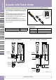
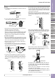
Mounting
➀
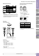
The HE9Z-GP15 and the HE1G/HE1G-L are installed as shown in the
following figure.
HE1G
HE9Z-GP15
➁
Secure the actuator using the attached two screws in the direction
of the arrow as shown in the following figure.
Bottom View)
Attached Screw
2-M4 Self-tapping Screws
Screws
• Using the attached screws (M4 self-tapping screw × 2), secure the
HE9Z-GP15 to the grip style enabling switch.
Recommended tightening torque: 1.0 ±0.1 N·m
Do not use excessive force to tighten the HE9Z-GP15 onto the switch,
otherwise the mounting holes will become deformed and the HE9Z-
GP15 cannot be secured. Prevent the screws from loosening by
applying epoxy. (Recommended: LOCTITE 425, ThreeBond 1401)
Precautions for Installation
• When using the HE9Z-GP15 for safety-related equipment in a con trol
system, refer to safety standards and regulations in each coun try and
region to make sure of correct operation. Also, perform a risk assess-
ment to ensure safety before starting operation of the machine.
• Read the instruction sheets for both the grip style enabling switch
and interlock switch to be used.
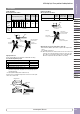
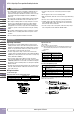
• Insert the HE9Z-GP15 in the direction shown in the following gure
only. Do not insert from any other direction. Also, do not use the slot
plug attached to the interlock switch.
Grip Style
Enabling
Switch
HE9Z-GP15
Interlock Switch
Actuator
Entry Slot
Actuator
Entry Slot
Correct Incorrect
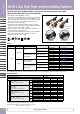
• See below for vertical installation. Do not install in any other direc-
tion. Also, make sure that the mounting surface is provided for the
entire area of the grip style enabling switch, so that the switch does
not tilt as shown below. Otherwise the HE9Z-GP15 actua tor will be
deformed.
Mounting Surface for
Interlock Switch
UP
DOWN
Correct Incorrect
• Do not install the grip style enabling switch and the interlock switch
in an area subjected to vibration. Excessive vibration may cause mal-
function of the switch contacts of the grip style enabling switch. Also,
exposure to vibration for a long period of time can cause scratching
and deformation of plastic parts.
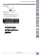
• When installing or removing the grip style enabling switch, do not use
excessive force in any direction other than shown in the fol lowing
gure. Otherwise the HE9Z-GP15 actuator can become deformed or
damaged.
Mounting Surface for
Interlock Switch
Removal/Installation
Direction
• Make sure that the HE9Z-GP15 actuator is inserted completely into
the interlock switch. Avoid any foreign objects between the actuator
and interlock switch as they may interfere with the plastic spring,
resulting in possible damage to the actuator.
Close-up
View
Plastic Spring
Complete Installation
Incomplete Installation
Gap
No gap
• When manually unlocking the HS5E interlock switch attached to
the grip style enabling switch, bend the spiral part of the connector
slightly to be able to access the manual unlock key.
Manual Unlocking
HS5E Interlock Switch
Spiral Part
of Connector
• Do not apply excessive shocks to the HE9Z-GP15 when attached to
the interlock switch, otherwise the actuator may be removed from
the interlock switch. Also excessive shocks may result in damage or
failure of the interlock switch.
• When the plastic part of the HE9Z-GP15 or the actuator is dam aged
or deformed, stop using immediately.
• The HE9Z-GP15 is used for HE1G/HE1G-L/HE2G grip style enabling
switch and HS5D/HS5B/HS5E/HS5E-K interlock switches only. Do not
use the HE9Z-GP15 for other prod ucts.
• Do not modify or disassemble the HE9Z-GP15.
Instructions