
Datasheet


www.apem-idec.eu
D-092
APEM
Switches &
Pilot Lights
Control Boxes
Emergency
Stop Switches
Enabling
Switches
Safety Products
Explosion Proof
Terminal Blocks
Relays & Sockets
Circuit
Protectors
Power Supplies
LED Illumination
Controllers
Operator
Interfaces
Sensors
AUTO-ID
Enabling Switches
HE1B
HE2B
HE3B
HE5B
HE6B
HE2G
HE1G-L
Actuator w/
Plastic Holder
HE1G-L Grip Style Three-position Enabling Switches
Instructions
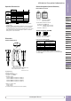
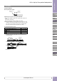
Connector Terminal
Wire Length inside the Switch
Sheath Strip
20 ±2mm
A
pplicable Connector
on Cable Side
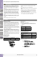
Applicable wire size for the cable gland on cable side
• 0.05 to 0.86mm
2
(AWG18 to 30): Check the compliance with receptacle and
contact.
Tool: 1762846-1 (manual tool)
Observe the requirements of GS-ET-22: 2003, 4.2.6 for wiring.
Note: When using stranded sires, make sure that loose wires do not cause short
circuit. Also, do not solder the terminals to prevent loose wires. Use copper
wire of 60°C or 75°C temperature rating in order to comply with UL508.
Observe the requirements of GS-ET-22: 2003, 4.2.6 for wiring.
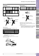
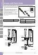
Recommended Tightening Torque
Parts for Tightening Torque
A Base and rubber kit (M4 screw × 3) 1.1 to 1.3 N·m
B Cable gland and grip style enabling switch 3.7 to 4.3 N·m
C Cable gland 3.7 to 4.3 N·m
D Do not touch —
Note: The recommended tightening torques of B and C are for the supplied cable
gland. When using another cable gland, refer to the tightening torque of
the cable gland used.
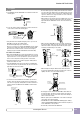
Rubber Boot Kit
Cable Gland
Base
Base
Rubber Boot Kit
BC
D
A (M4 screw × 3)
Base
D